
Overview & Concepts
The Scheduler function in EasyBuilder Pro allows the HMI to execute predefined actions automatically at specified dates and times. It provides a built-in method for time-based automation without requiring PLC logic or macro programming. The Scheduler relies on the HMI system clock to determine when scheduled tasks should occur.
A scheduled task is configured by defining:
- The date and time the task should run
- The repetition pattern (such as daily or weekly)
- The system action to execute
When the scheduled time is reached, the HMI automatically performs the configured action. Typical uses include running periodic system functions, exporting data, or triggering routine operations at predetermined times. Because it operates through project configuration, the Scheduler provides a simple way to automate recurring tasks within the HMI environment.

Implementation
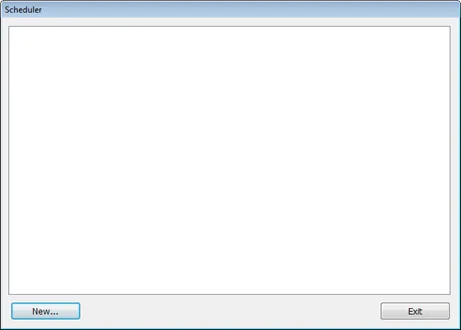
Click [Object] » [Time-related] » [Scheduler] icon on the toolbar to open the Scheduler management dialog box, click [New] to open the Scheduler property setting dialog box.
General Tab
| Setting | Description |
|---|---|
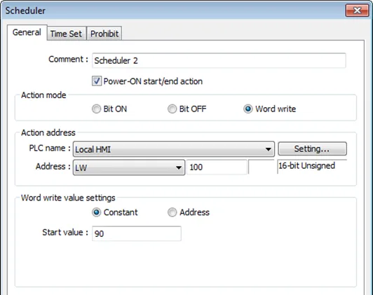
| Power ON start/end action | Execute the defined action when the HMI is powered ON. Enabled When HMI is powered ON within the scheduled time range, the start action will be performed automatically. When HMI is powered ON outside the scheduled time range, the termination action will be executed. Disabled When the HMI is powered ON at a time later than the start time, the start action will not be performed, but the termination action will be performed. When the termination action is not defined, the scheduled range is not recognized and no action is performed. |
| Action mode | Choose the action to do at the given time. Bit ON At the start time, set the designated bit ON. At the end time, set the designated bit OFF. Example: Start time: 09:00:00 End time : 17:00:00 Bit OFF At the start time, set the designated bit OFF. At the end time, set the designated bit ON. Example: Start time: 09:00:00 End time : 17:00:00 Word write The [Write start value] entered here is transferred to the designated [Action address] word register at the start time. At end time, the [Write end value] entered here is written to the [Action address]. The values can be entered manually or be set by using [Address] mode. In [Address] mode, the value in the specified address is the start value where the value in [Address +1] is the end value. Example: Device address: LW-100 Start time: 09:00:00 End time: 17:00:00 Write start value: 10 Write end value: 0 Use register: If control address is LW-n, then enter 10 in LW-n and enter 0 in LW-(n+1). |
Time Set Tab
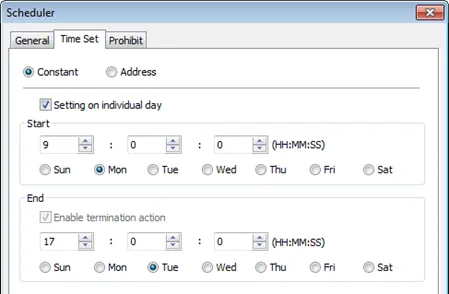
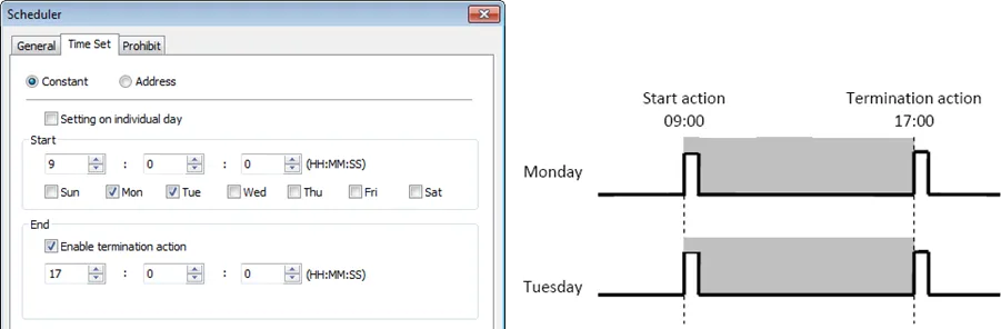
Specify start time and end time. [Constant] allows specifying a date or period and time. [Address] allows controlling the time by the designated address.
Constant
Notes:
If [Setting on individual day] is selected:
- Start and end time must be entered.
- Start and end time must be on a different time, or same time but different day.
- The same start time and end time can be assigned to different days of the week.
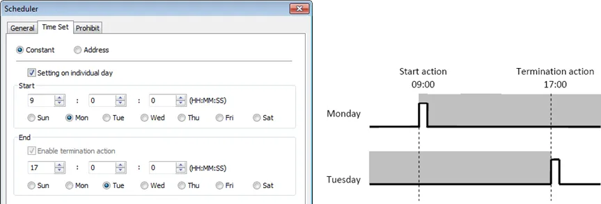
If [Setting on individual day] is NOT selected:
- Start and end time must be on a different time, different day.
- If an end time is earlier than a start time, the end action will occur in the next day.
- The start time and end time entered must start and end within a 24 hour period.
Address
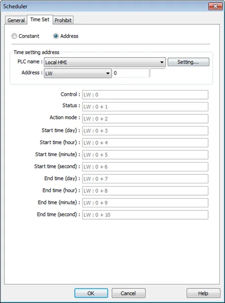
The scheduler object retrieves the start/end time and day of week information from word registers, enabling all parameters to be set and changed under PLC or user control.
Designated as the top address in a block of 11 sequential registers which are used to store time setting data.
The format of the 11 word registers should normally be 16-unsigned integer. If a 32-bit word address is chosen, only bits 0-15 are effective, and bits 16-31 should be written as zero.
The following describes each register:
- Control (Time setting address + 0)
- When [Control] bit is ON, the HMI will read and update [Action mode], [Start time], and [End time] values.

- Status (Time setting address + 1)
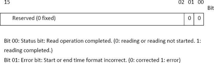
- When the read operation is completed, Bit00 of this register turns ON. If time data read is out of range or incorrect in any way Bit 01 turns ON.
Note:
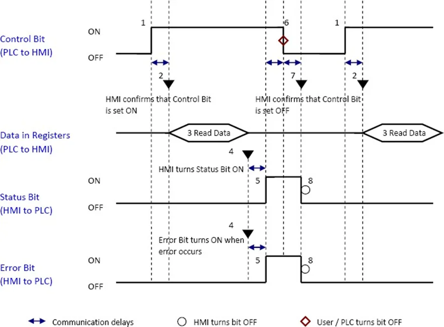
- After the scheduler reads the data and the status is turned ON (The value in [Address + 1] = 01), the control bit must be turned OFF (address = 0). The status bit and error bit will be turned OFF (1 -> 0) at the same time
Action mode (Time setting address + 2)
- Enable/disable [Enable termination action] and [Setting on individual day]. Whatever the [Enable termination action] bit is, all the time data, from [Control] to [End time (second)], will be read.
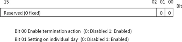
Notes:
- If [Enable termination action] is OFF, all 11 registers are still read but end time is ignored.
- If [Setting on individual day] is ON, make sure that all start end times are entered. If more than one start / end day bit is ON, and error will occur.
Start / End Day (Start Day: Time setting address + 3, End Day: Time setting address + 7)
- Designates which day of week is used to trigger the start or end action.
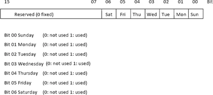
Start / End Time (Start Time: Time setting address + 4 to + 6, End Time: Time setting address + 8 to + 10)
- Hour: 0 – 23 Minute: 0 – 59 Second: 0 – 59 Values outside these ranges will cause error.
Notes:
- 16-bit unsigned integer format must be used; BCD format is not supported here.
- In [Address] mode, [Control] bit should be set after HMI reboots to update scheduler time.
- When using RW address, [Control] bit should be set after HMI reboots to update scheduler time. Placing a Set Bit object with [Set ON when window opens] selected in the common window is recommended, this can retain last settings after HMI reboots.
- End time depends on [Action mode] (address + 2). [Enable termination action] (Bit 00) and [Setting individual day] (Bit 01) are related:

Prohibit Tab
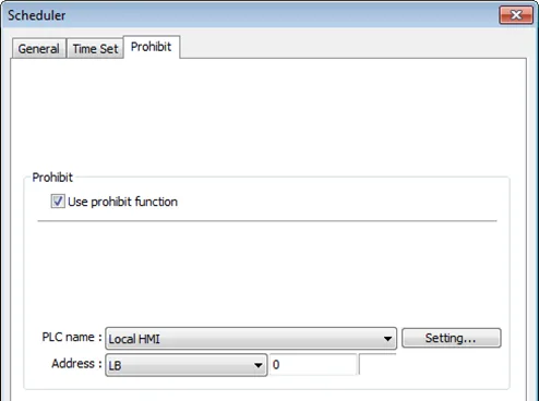
Before the scheduled action is performed, the HMI will read the specified bit state. If it is ON, the scheduled start/end action will be skipped. Otherwise, it will be performed normally.
Notes:
- The maximum number of Scheduler objects in a project is 64.
- A time schedule applies one action only when the start time is reached.
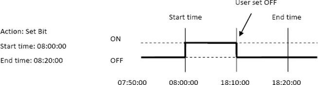
- [Write start/end value] and [Prohibit] bit is read only once before start action. After that, even to change the state of [Prohibit] bit or [Write start/end value], the end action and the value written will not be affected. Also, to read data of [Write start/end value] and [Prohibit] bit, there is a delay of start action due to the communication.
- Each time RTC data is changed, scheduler list entries that possess both start and end times will be checked for in-range or out-range conditions. For in-range, the start action will occur. If the end action is not set, the new range is not recognized, the action will not occur.
- If several Scheduler objects are set to the same start time or end time, the action is performed in ascending order of the schedule number.
- In [Time Set] » [Address] mode, the system will read [Control] word regularly. The length of the period depends on the system.
- In [Time Set] » [Address] mode, when start time and end time is out- range, error occurs in the set action time. (Note: BCD is not an acceptable format)
- In [Time Set] » [Address] mode, the action will not start up until the first time the time data is successfully updated.
Scheduler Examples
Example 1
A motor is scheduled to power – ON at 9:00 and power – OFF at 18:00, Monday to Friday.
We are using LB-100 to control the motor state. LB-100 will be set ON at 9:00 and OFF at 18:00.
Instructions: Example 1
Make new Scheduler Object
Click the Scheduler icon on the toolbar to open the Scheduler management dialog box,
click [New].
Define the Actions
In [General] tab, select [Bit ON] in [Action mode] and set [Action address] to LB-100.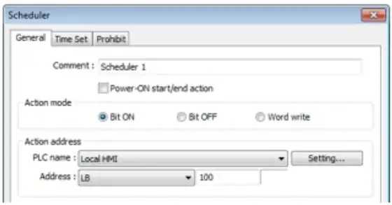
Configure the time setting
In [Time Set] tab, select [Constant]Configure the Start time
Enter [Start] time as 9:00:00 and select Monday to Friday. Do not select [Setting on
individual day].
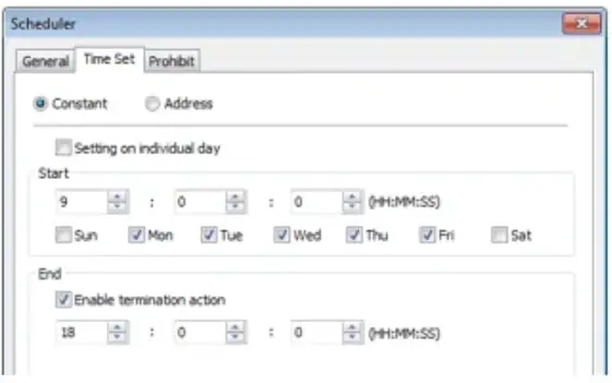
Configure the End time
Enter [End] time as 18:00:00 and select [Enable termination action] check box.Click OK.
Click [OK], a new Scheduler object will be created on the [Scheduler] list.
Example 2
A thermal heater is scheduled to heat up to 90C at 08:00 and cool down to 30C at 17:00,
Monday to Friday. LW-100 is used to store the set point value.
Instructions: Example 2
Make new Scheduler Object
Click the Scheduler icon on the toolbar to open the Scheduler management dialog box,
click [New].
Define the Actions
In [General] tab, select [Word write] in [Action mode] and set [Action address] to LW-100Configure the Word Write Value
Select [Constant] for [Word write value settings] and enter 90 in [Start value].Remember, this value is our heat-up value (90*C) at the start of the day.Configure the time setting
In [Time set] tab select [Constant].Configure the Start time
Enter [Start] time as 8:00:00 and select Monday to Friday. Do not select [Setting on
individual day].
Configure the End time
Enter [End] time as 17:00:00 and select [Enable termination action] check box.Define an End Value
Return to [General] tab and enter 30 in [End value].Remember, this value is our cool-down value (30*C) at the end of the day.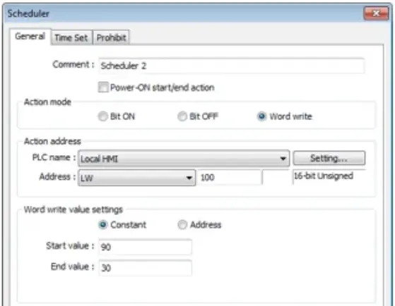
Click OK.
Click [OK], a new schedule object will be created on the [Scheduler] list.