
Overview & Concepts
The Multi-HMI feature in EasyBuilder Pro allows multiple HMIs to communicate with each other over an Ethernet network. This enables one HMI to access and exchange data with another HMI, allowing distributed operator interfaces to share information and coordinate system operation.
In a Multi-HMI configuration, each HMI is assigned an IP address and added as a device within the project. Once configured, registers in one HMI can be read or written by another HMI across the network. This allows shared data to be displayed or controlled from multiple locations.
Typical uses of Multi-HMI communication include:
- Sharing machine status information between operator stations
- Allowing multiple HMIs to monitor the same process data
- Coordinating control between different interface panels in a system
Implementation (HMI to Remote HMI)
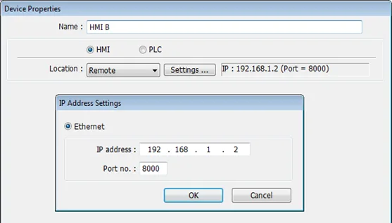
To exchange data between one HMI and another HMI, the other HMI needs to be configured as a “Remote HMI” within the EasyBuilder Pro System Parameter Settings menu. For example, HMI A wants to control an object on HMI B. HMI A’s IP Address will be 192.168.1.1, while the IP Address of HMI B will be 192.168.1.2 for this example.
In HMI A’s System parameter Settings menu, HMI B is added as a “Remote HMI”.
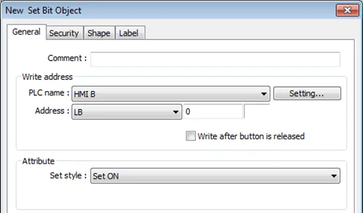
In the Project of HMI A, reference HMI B from any object (Set Bit Object shown below):
Note:
One HMI can handle requests from up to 64 other HMIs simultaneously. However, the practical limitations of such a configuration will greatly depend on the specifics of your installation and operational environment.
Implementation (PLC Connected to Remote HMI via Serial Port)
In HMI A’s [System Parameter Settings] » [Device list] click [New HMI], and set the IP address to HMI B (IP: 192.168.1.2).
Once the Remote HMI has been created, click the [New PLC] option, and set the [Name] field to “PLC on HMI B”, or something else that reminds you you’re looking at the PLC connected to the secondary HMI:
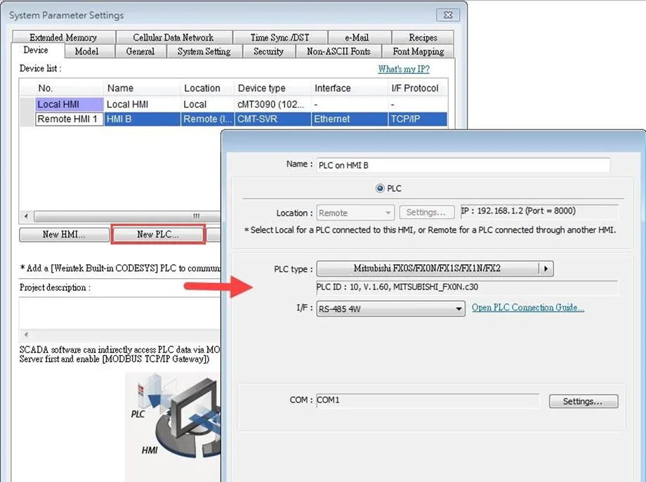
When finished, the “Remote PLC” can be found under the Remote HMI 1 entry.
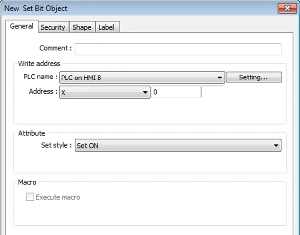
Create a Set Bit Object in the HMI A’s EasyBuilder project and then simply reference the PLC on HMI B entry in the object address section:
Notes:
- When the remote HMI in a cMT/cMT X Series project is an HMI5000B/L/XL/P Series model, please select [Support iP/iE/XE/eMT/mTV HMI communication protocol and EasyWatch] check box in the [Model] tab in [System Parameters].
![When the remote HMI in a cMT/cMT X Series project is an HMI5000B/L/XL/P Series model, please select [Support iP/iE/XE/eMT/mTV HMI communication protocol and EasyWatch] check box in the [Model] tab in [System Parameters]](https://media.maplesystems.com/wp-content/uploads/2026/04/image-190.webp "Supporting communications protocols of legacy series HMIs in a cMT or cMT X Series project")
- Similarly, when the remote HMI in an HMI5000 Series project is a cMT / cMT X Series model, please select [Support cMT communication protocol] to establish communication between cMT/cMT X and HMI5000B/L/XL/P Series models.
![When the remote HMI in an HMI5000 Series project is a cMT / cMT X Series model, please select [Support cMT communication protocol] to establish communication between cMT/cMT X and HMI5000B/L/XL/P Series model](https://media.maplesystems.com/wp-content/uploads/2026/04/image-189.webp "Supporting cMT / cMT X Series communication protocols in a legacy HMI project")