
Touch Gesture
Overview

For some time, smartphones or tablets nowadays have been using gesture-based operation, e.g., pinch with five fingers to close an app. Now, with HMI having Touch Gesture object that supports up to 23 touch gestures, HMI can provide operating experience comparable to that of a smartphone or tablet.
The Touch Gesture finger limit is 5.
Configuration
Click [Object] » [Action Related] »[Touch Gesture] icon on the toolbar to open the Touch Gesture property dialog box. Select a window and then add its allowable touch gestures.
General Tab
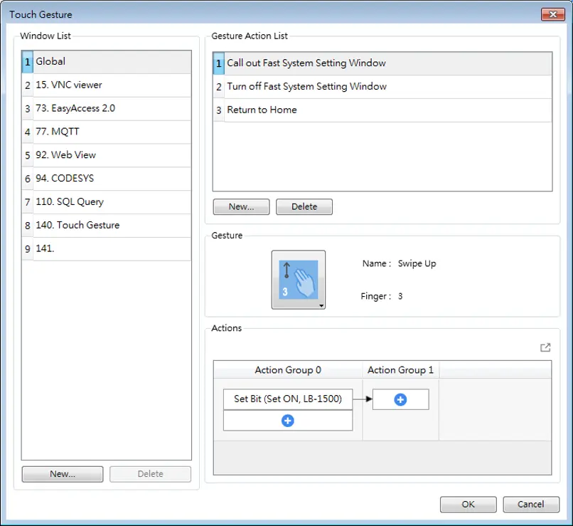
| Setting | Description |
|---|---|
| Window List | Allow the gesture actions to be used in a specific window or all windows. When Global is selected, one-finger gestures are not supported. Add/Delete Add or delete a window that allows this gesture action. |
| Gesture Action List | Shows gesture action list for the window. Add/Delete Add or delete a gesture action. |
| Actions | Set an action or group of actions triggered using this gesture. For more information on the actions, see Operation Log or Action Trigger pages. |
Notes:
- Up to 16 gestures can be used for each window setting (global/individual).
- When the same gesture is used in both the Global window and an individual window, the gesture is effective only for the individual window.
- When a user performs a gesture on the screen, objects are still triggered when they are touched.
- The touch gesture for an individual window is only effective when the window is a base window. If the said window is a pop-up window, or overlaid windows, its touch gesture will be ineffective and its gesture actions will not be executed.
- Detection for the next gesture will only start when the actions for the current gesture have been completed.

System Message Object
Overview
If objects use [Display confirmation request] or [local HMI supports monitor function only] is turned on/off, the corresponding messages configured here will be displayed in pop-up message boxes.
Configuration
Click the System Message icon on the toolbar to open the setting dialog box.
Sestem Message
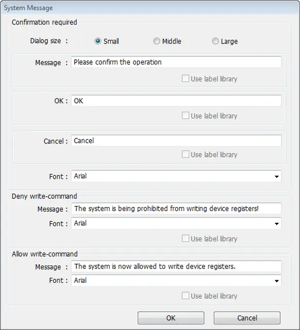
| Setting | Description |
|---|---|
| Dialog Size | Select the size for pop-up window and texts. |
| Confirmation required | If an object uses [Display confirmation request], this message would pop up when the object is used. [Message] shown on confirmation dialog box, and the text label of the 2 buttons, [OK] and [Cancel], can be set. Please use the same font for the labels of [Message], [OK] and [Cancel]. Additionally, only when selecting [Label Library] for [Message], the use of Label Library for [OK] and [Cancel] buttons can be enabled. |
| Deny write-command | Displays when system tag LB-9196 (local HMI supports monitor function only) is turned ON. |
| Allow write-command | Displays when system tag LB-9196 (local HMI supports monitor function only) is turned OFF. |

Moving / Rotating Shape
Overview
Moving / Rotating Shape is an object that changes its state, moves, and/or rotates according to the user-defined parameters. The state, moving distance, and rotation direction/angle are determined by values in consecutive registers.
Configuration
Click [Object] » [Animation] » [Moving / Rotating Shape] icon on the toolbar to create the object, set up the properties, press OK button, and a new Moving / Rotating Shape object will be created.
General Tab
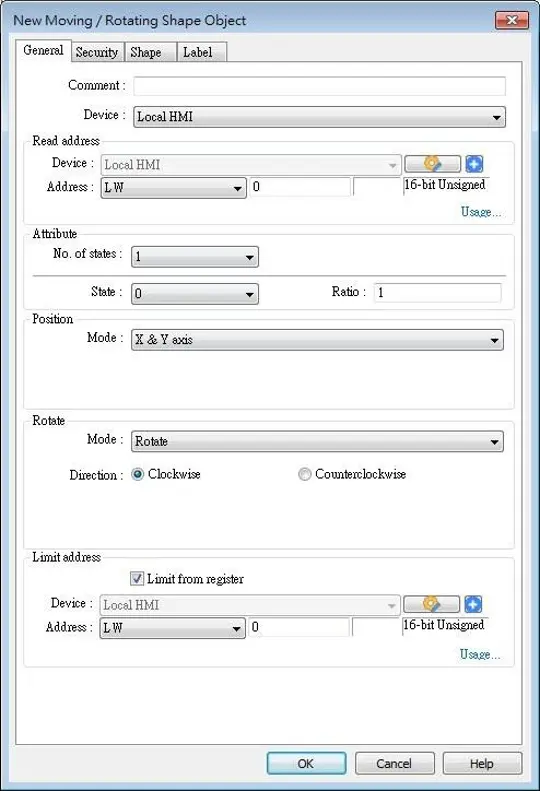
| Setting | Description |
|---|---|
| Read address | Click [Setting] to configure the [Device], [Device type], [Address], [System tag], or [Index register] of the word devices that control the display of object’s state and moving distance. Users can also set the address in [General] tab while adding a new object. |
| Attribute | Select the object’s movement mode and range. See the Moving Shape Modes section below for details. |
| Display ratio | The size of shape in different states can be set individually as shown: |
| Rotate | Select Clockwise or Counterclockwise for Direction and define the angle range (unit in degree) within which the object may rotate. The allowable range is 0~360 degrees, and the Max. angle should be greater than Min. angle. For more information please see the Rotating Shape Modes section below |
| Limit address | The object’s moving range can be set by adjusting the data in the designated register, see Example below. |
Example
Supposed that the object’s moving range is limited by register LW-n, the addresses in the following table are used to limit the moving / rotating range.
| Data Format | 16-bit | 32-bit | 64-bit (cMT / cMT X only) |
|---|---|---|---|
| Position – [Min. X] address | LW-n | LW-n | LW-n |
| Position – [Max. X] address | LW-n+1 | LW-n+2 | LW-n+4 |
| Position – [Min. Y] address | LW-n+2 | LW-n+4 | LW-n+8 |
| Position – [Max. Y] address | LW-n+3 | LW-n+6 | LW-n+12 |
| Rotate – Input Low | LW-n+4 | LW-n+8 | LW-n+16 |
| Rotate – Input High | LW-n+5 | LW-n+10 | LW-n+20 |
| Rotate – Scaling Low | LW-n+6 | LW-n+12 | LW-n+24 |
| Rotate – Scaling High | LW-n+7 | LW-n+14 | LW-n+28 |
Moving Shape Modes
X-Axis Only
The object is only allowed to move along the X-axis. The moving distance ranges from [Min. X] to [Max. X].
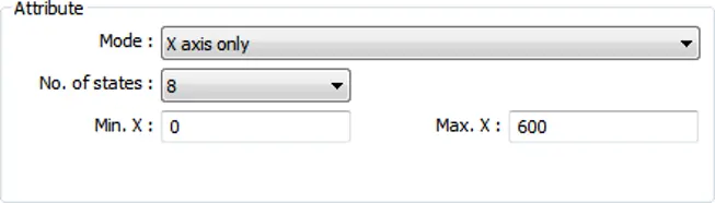
| Data format | 16-bit | 32-bit | 64-bit (cMT / cMT X only) |
|---|---|---|---|
| Object state | LW-n | LW-n | LW-n |
| Moving distance on X-axis | LW-n+1 | LW-n+2 | LW-n+4 |
Y-Axis Only
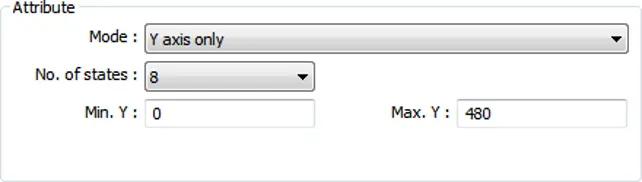
| Data format | 16-bit | 32-bit | 64-bit (cMT / cMT X only) |
|---|---|---|---|
| Object state | LW-n | LW-n | LW-n |
| Moving distance on Y-axis | LW-n+1 | LW-n+2 | LW-n+4 |
X And Y axis
The object is allowed to move along the X-axis and Y-axis. The moving range in X and Y directions is defined by [Min. X], [Max. X] and [Min. Y], [Max. Y] respectively.
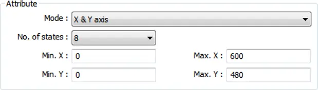
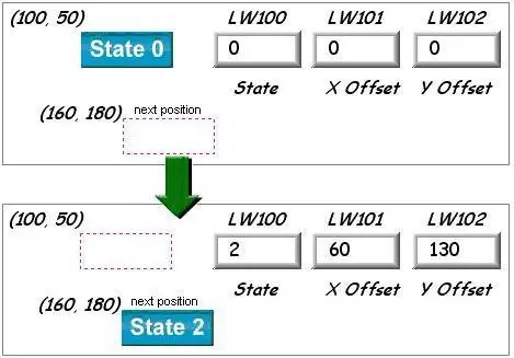
For example, if the object’s read address is LW-100 and the data format is [16-bit Unsigned], LW-100 is used to control the object’s state, LW-101 is used to control the object’s moving distance on the X-axis, and LW-102 is used to control the object’s moving distance on the Y-axis.
The following figure shows that the object’s read address is LW-100 and initial position is (100, 50). To move the object to the position (160,180) and change its state to State 2, assign 2 to LW-100, 160-100 = 60 to LW-101, 180-50 = 130 to [LW102].
X Axis With Scaling
The object moves in X-axis only with scaling. Suppose that the value of the designated register is DATA, the system uses the following equation to calculate the moving distance on the X-axis.

| Data format | 16-bit | 32-bit | 64-bit (cMT / cMT X only) |
|---|---|---|---|
| Object state | LW-n | LW-n | LW-n |
| Moving distance on X-axis | LW-n+1 | LW-n+2 | LW-n+4 |
Y-Axis With Scaling
The object is for Y axis movement with scale, and the equation to calculate the moving distance on the Y-axis is the same as the X-axis with scaling.
| Data format | 16-bit | 32-bit | 64-bit (cMT / cMT X only) |
|---|---|---|---|
| Object state | LW-n | LW-n | LW-n |
| Moving distance on Y-axis | LW-n+1 | LW-n+2 | LW-n+4 |
X-Axis with Reverse Scaling
This works in the way as [X axis w/ scaling], but the moving direction is in reverse.
Y-Axis with Reverse Scaling
This works in the way as [Y axis w/ scaling], but the moving direction is in reverse.
Rotating Shape Modes
The addresses that control the moving / rotating shape are consecutive addresses starting from Read Address (LW-n), and they may vary depending on the selected mode. Please click [Usage…] to open the window that shows the control addresses relating to rotation parameters.

Rotate
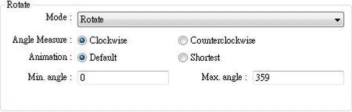
Select rotating direction from clockwise or counterclockwise and set the Min. and Max. angle range.
When rotation animation is enabled, two modes can be selected: Default and Shortest.
e.g. When the angle measure is set to clockwise and the rotating angle is changed from 10 degrees to 350 degrees, these two modes give different results:
- Default: rotates 340 degrees clockwise (linear interpolation between the two numbers)
- Shortest: rotates 20 degrees counterclockwise (in the direction that produces the shortest animation path)
Rotate with Scaling
Select rotating direction from clockwise or counterclockwise. The angle of rotation is calculated by the formula as shown below:

Rotate with Reverse Scaling
Similar to [Rotate w/ scaling] but reverses the object from clockwise to counterclockwise and vice versa.

Animation
Overview
Animation object is defined by a pre-defined point set and states. Animation object will then move to a given point in a given state defined by designated registers. The object state and position depend on current value of two consecutive registers. The first register controls the state of the object and the second register controls the position along the predefined path.
Configuration
Click [Object] » [Animation] » [Animation] icon on the toolbar. First, create the pre-defined path. Move the mouse to each moving position, and click the left button to define positions one by one. When it is done, right click on the screen, set up the properties, press OK button, and a new Animation object will be created.
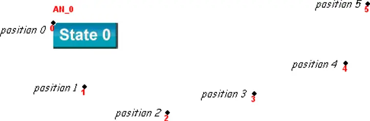
To change the object’s attributes, double click on the object to open Animation Object’s Properties dialog box.
General Tab
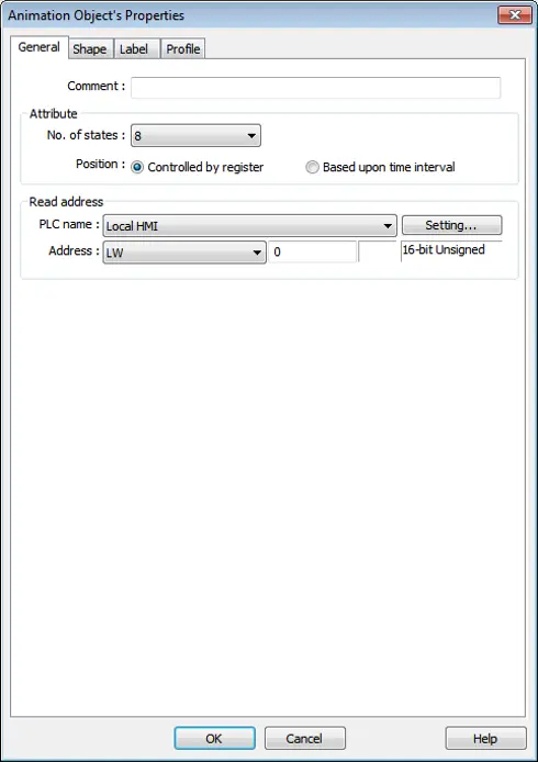
| Setting | Description |
|---|---|
| Attribute | No. of states Configure the number of states for this object. Controlled by register Use the designated registers to control the object’s state and position. See Example. Based upon time interval The object’s state and position will change from time to time. [Time interval attributes] is used to set the time interval for states and positions. 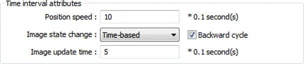 Position speed: The speed of movement. The unit is 0.1 second. Supposed that [Speed] is set to 10, the object’s position will change each second. Image state change: Determines how state changes, either [Position dependent] or [Time-based]. If [Position dependent] is selected, the object state will change when position changes. If [Time-based] is selected, the object position will change based on [Position speed] and the object state will change based on [Image update time]. Backward cycle: Assumed the object has four positions: position 0, position 1, position 2, and position 3, and [Backward cycle] is not selected. When the object moves to the last position (position 3), the next position will be back to the initial position 0, and repeat. The moving path is shown as follows: position 0 → position 1 → position 2 → position 3 → position 0 → position 1 → position 2… If [Backward cycle] is selected, when the object moves to the last position (position 3), it will move backwards to position 2, position 1 and then the initial position 0, and start over again. The moving path is shown as follows: position 0 → position 1 → position 2 → position 3 → position 2 → position 1 → position 0… |
Example
The object’s state and position are determined by the registers, and the addresses must be configured correctly, as in the following table:
| Data format | 16-bit | 32-bit | 64-bit (cMT / cMT X only) |
|---|---|---|---|
| Object state | LW-n | LW-n | LW-n |
| Object position | LW-n+1 | LW-n+2 | LW-n+4 |
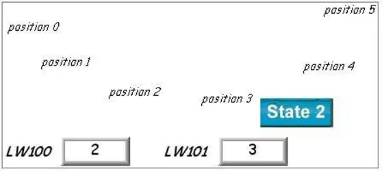
For example, if the designated register is LW-100 and the data format is [16-bit Unsigned], then LW-100 represents object’s state, LW-101 represents position. In the picture below, LW-100 = 2, LW-101 = 3, so the object’s state is 2 and position is 3.
Profile Tab
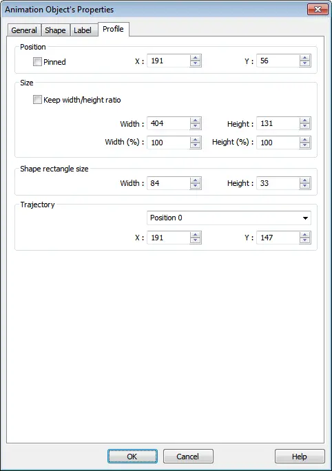
| Setting | Description |
|---|---|
| Shape rectangle size | Set the size of the shape. |
| Trajectory | Set the position of each point on the moving path. |
Note:
- Since multiple pictures might be used by an [Animation] object, [Set to original dimension] will not return all pictures to the original size.

Event Bar Chart (cMT / cMT X Series)
Overview
Event Bar Chart is a type of easy-to-use bar chart that can comprehensively illustrate project schedule. Using Event Bar Chart to illustrate HMI events or alarms can help users to clearly understand the time at which an event or alarm occurs, and its duration. Before drawing an Event Bar Chart, please configure Event Log object first.
This feature is only supported on cMT / cMT X Series models (excluding cMT-Gateway).
Event Log Configuration
Event Log
Click [Data/History] » [Event Log] in the menu to configure several event logs. This section describes the Event Bar Chart related settings that can be found in the Event Log settings dialog box.
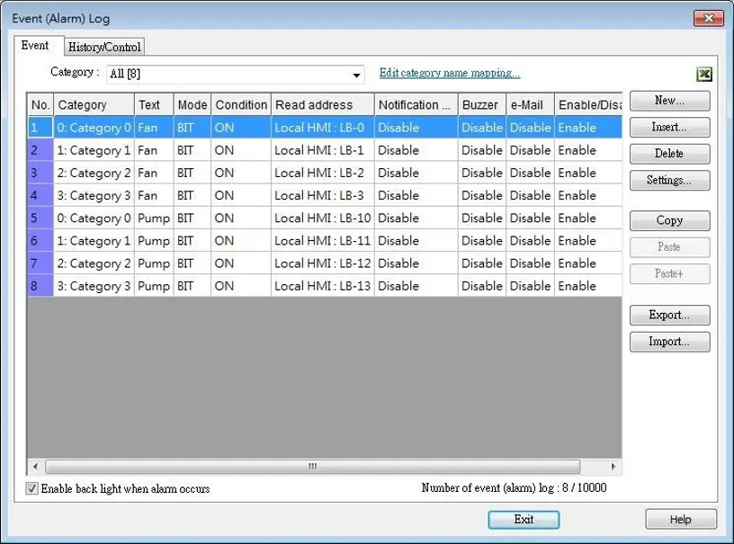
| Setting | Description |
|---|---|
| Edit category name mapping | Event Bar Chart will show the name of each category. |
General Tab
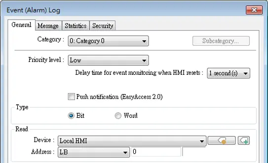
| Setting | Description |
|---|---|
| Category | Event Bar Chart will illustrate the duration of all events inone category; please select correct category in this field. |
Message Tab
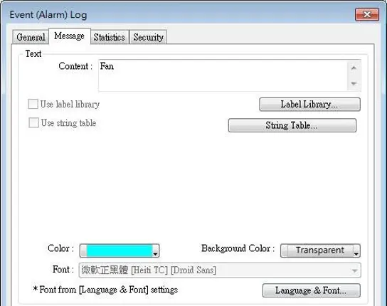
| Setting | Description |
|---|---|
| Text | Enter the name of the event log. |
| Color | Select the color for the bar shown in Event Bar Chart that illustrates this event log. |
Event Bar Chart Configuration
Click [Data/History] » [Event Bar Chart] in the menu to draw an Event Bar Chart.
General Tab
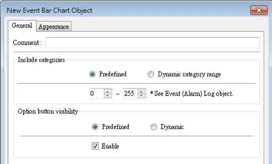
| Setting | Description |
|---|---|
| Include categories | Predefined Predefine a range of event categories to be displayed in the Event Bar Chart. Dynamic category range Use a set of consecutive addresses to select the display range of event categories dynamically. 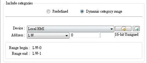 |
| Option button visibility | Show or hide the option button of the object. Predefined Select [Enable] to show the option button. Dynamic Choose a bit address to control option button visibility. 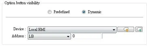 |
Appearance Tab
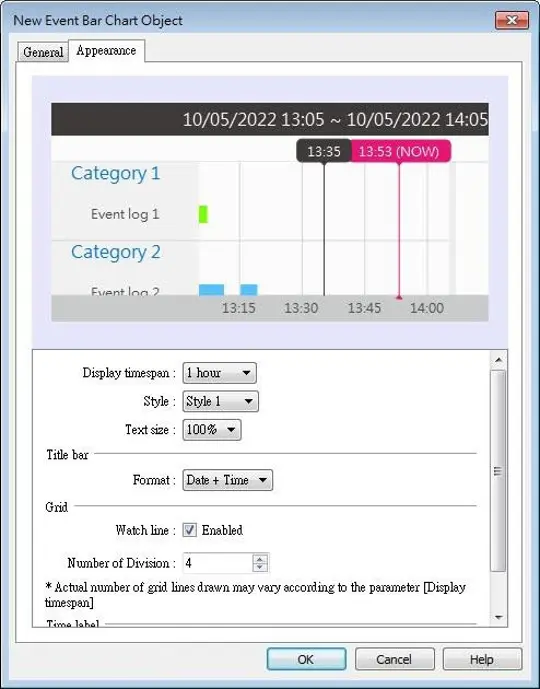
| Setting | Description |
|---|---|
| Display timespan | Specify the time interval that is measured as a number of hours. Events occur during this time interval will be illustrated in Event Bar Chart. Tapping the option button in the upper right corner of the HMI screen can also change this setting.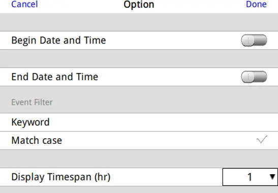 See the HMI Settings section below for a desciption of this screen |
| Style | By default 3 styles are provided for users to choose from. |
| Text size | Text sizes range from 50%~200%. |
| Title bar Format | Date + Time: 08/16/2018 13:55 ~ 08/16/2018 14:55 Date only: 09/03/2018 ~ 09/04/2018 Time only: 13:57 ~ 14:57 |
| Watch line | A watch line shows at the point in the Event Bar Chart that is touched. The time represented by the touched point will show at the top of the watch line. |
| Number of Division | The number of divisions on X axis. |
| Time label | The format in which the time label is displayed. |
HMI Settings
On cMT HMI or cMT Viewer, tap the options button in the upper-right corner of the object to open the following settings window:
| Setting | Description |
|---|---|
| Begin Date and Time | Specify the begin date and time at which Event Bar Chart displays data. By default this setting is disabled, and Event Bar Chart displays from the begin date and time of the stored data. |
| End Date and Time | Specify the end date and time at which Event Bar Chart displays data. By default this setting is disabled, and Event Bar Chart ends at the end date and time of the stored data. |
| Event Filter | Keyword Events can be filtered by entering a keyword. Match case Use case-sensitive search when searching for events in English. |
| Display Timespan (hr.) | Dynamically change the time range (1~96 hours.) shown in Event Bar Chart. Select all to display all existing events. |
Note:
- When HMI power is off, the HMI will not be able to obtain the alarm states; therefore, the alarm states during the power off period will not be illustrated in Event Bar Chart, not even after the power turns on.

Import/Export Object
Overview
With Import/Export object, Recipe Database or String Table can be imported or exported.
Configuration
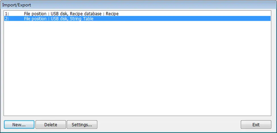
Click the Import/Export icon on the toolbar to open the Import/Export Object management dialog box. To add an Import/Export object, click [New], set up the properties, press OK button and a new Import/Export object will be created.
General Tab
| Setting | Description |
|---|---|
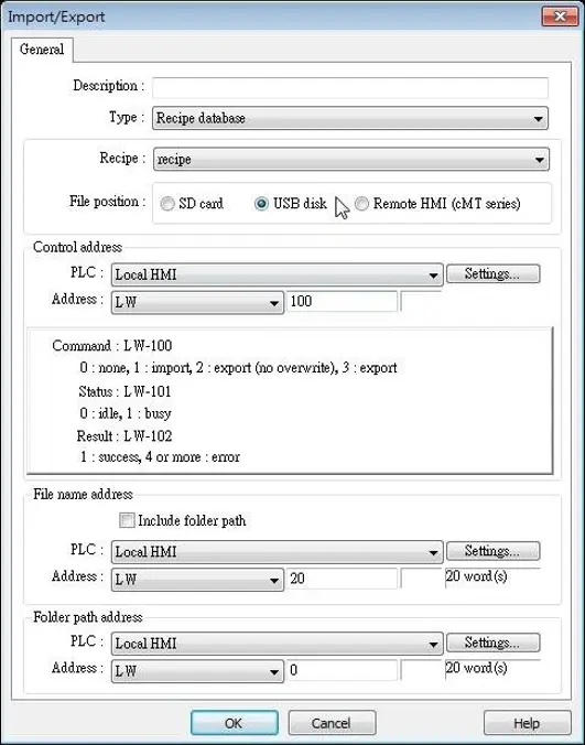
| Type | Select the file source from Recipe Database or String Table. |
| File position | Select the position of the file to be imported / exported from SD card, USB disk, or Remote HMI (cMT / cMT X Series). When Remote HMI is selected, please note that only files in cMT / cMT X Series models can be imported. |
| Recipe | Select the recipe. This option is hidden when select String Table. |
| Control address | Designate the control address used for performing import/export, or displaying the result. Control: Control Address Recipe Database: 0: None 1: Import 2: Export (no overwrite) 3: Export String Table: 0: None 1: Delete 2: Import 4: Export (no overwrite )5: Export Status: Control Address+1 0: Idle 1: Busy Result: Control Address+2 1: Success 4: The file already exists, no overwriting. Other: Error |
| File name address | The name of the imported/exported file. If [Include folder path] is selected, the full directory and file name will be included at this address. |
| Folder path address | The directory of the imported/exported file. |
| Remote HMI address | When the file position is [Remote HMI (cMT / cMT X Series)], please enter the remote HMI’s IP address in this field. |
Example
The following is an example on recipe export/import settings.
| Field | Setting |
|---|---|
| File position | USB disk |
| Recipe | Recipe_A (or other recipe) |
| Control address | LW-100 |
| File name address | LW-200 |
| Folder path address | LW-250 |
- Create two ASCII Input objects. Set address to LW-200 and LW-250 respectively.
- Enter the file name in LW-200: 2015_recipe.csv.
- Enter the folder path in LW-250: Setting.
- Use a Set Word object to write value 3 to LW-100. Then, Recipe_A will be exported to the USB disk, in the “Setting/2015_recipe.csv” file
Note:
When performing “Export (no overwrite)” command, if the target file already exists, the export operation will be canceled, and the result value will be set to “4”.
The following lists the result values and the information:
| Result (HEX) | Information |
|---|---|
| 0x1 | Success. |
| 0x4 | File already existed and will not overwrite. |
| 0x10 | Invalid command. |
| 0x100 | Data contains non-numeric data. |
| 0x101 | Path contains invalid string “../”. |
| 0x102 | Communication error while updating Recipe DB. |
| 0x103 | Error while reading Recipe DB information from project file. |
| 0x200 | General exception. |
| 0x201 | General status error. |
| 0x202 | Import to unknown database type. |
| 0x203 | Error while validating Recipe DB table definition. |
| 0x204 | Error while validating Recipe DB table data. |
| 0x205 | Error while writing Recipe DB table definition. |
| 0x206 | Error while writing Recipe DB table data. |
| 0x300 | File error: Unknown error. |
| 0x301 | File error: Empty file name. |
| 0x302 | File error: The external device does not exist. |
| 0x303 | File error: Invalid file name (directory or special files), or a folder with the same name already exists. |
| 0x304 | File error: Unable to remove file. |
| 0x305 | File error: Open file stream error. |
| 0x306 | File error: Unhandled BOM. |
| 0x307 | File error: Error while parsing CSV file (incorrect formats). |
| 0x308 | File error: Insufficient space on the external device. |
| 0x309 | File error: Unable to find the file. |
| 0x30A | File error: The CSV file contains over 10000 data rows. |
| 0x400 | Database general exception. |
| 0x401 | Database error: Unable to open table. |
| 0x402 | Database error: Unable to get rows. |
| 0x403 | Number of columns in CSV file and in Recipe DB do not match. |
| 0x501 | Unable to connect remote HMI. |
| 0x503 | Import from remote HMI database is prohibited. |
| 0x504 | Import from remote HMI database is not supported. |