Use the Free Protocol to Control a Device
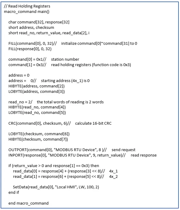
If EasyBuilder Pro does not provide a driver for a specific device, users can use OUTPORT and INPORT built-in functions to control the device. The data sent by OUTPORT and INPORT must follow the communication protocol of the device. The following example explains how to use these two functions to control a MODBUS RTU device.
First, create a new device in the device table. The device type of the new device is set to “Free Protocol” and named with “MODBUS RTU device” as follows:
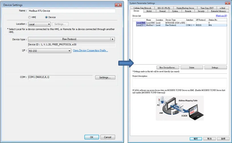
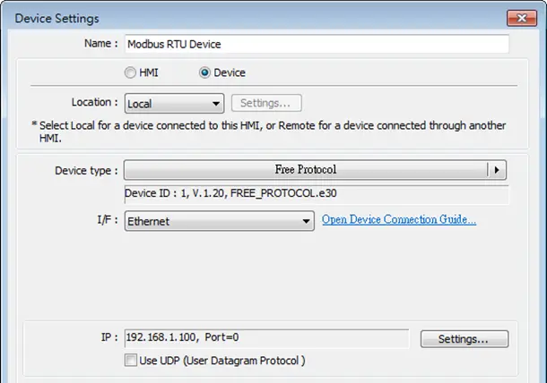
The interface of the device (I/F) uses [RS-232]. If a MODBUS TCP/IP device is connected, the interface should be [Ethernet] with correct IP and port number as follows:
Suppose that the HMI will read the data of 4x_1 and 4x_2 on the device. First, utilize OUTPORT to send out a read request to the device. The format of OUTPORT is:
OUTPORT(command[start], device_name, cmd_count)
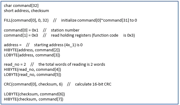
Since “MODBUS RTU device” is a MODBUS RTU device, the read request must follow MODBUS RTU protocol. The request uses “Reading Holding Registers (0x03)” command to read data. The following picture displays the content of the command. (The items of the station number (byte 0) and the last two bytes (CRC) are ignored).
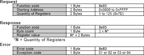
Depending on the protocol, the content of a read command as follows (The total is 8 bytes):
- command[0]: station number (BYTE 0)
- command[1]: function code (BYTE 1)
- command[2]: high byte of starting address (BYTE 2)
- command[3]: low byte of starting address (BYTE 3)
- command[4]: high byte of quantity of registers (BYTE 4)
- command[5]: low byte of quantity of registers (BYTE 5)
- command[6]: low byte of 16-bit CRC (BYTE 6)
- command[7]: high byte of 16-bit CRC (BYTE 7)
So a read request is designed as follows:
Lastly, use OUPORT to send out this read request to the device.

After sending out the request, use INPORT to get the response from the device. Depending on the protocol, the content of the response is as follows (the total byte is 9):
- response[0]: station number (BYTE 0)
- response[1]: function code (BYTE 1)
- response[2]: byte count (BYTE 2)
- response[3]: high byte of 4x_1 (BYTE 3)
- response[4]: low byte of 4x_1 (BYTE 4)
- response[5]: high byte of 4x_2 (BYTE 5)
- response[6]: high byte of 4x_2 (BYTE 6)
- response[7]: low byte of 16-bit CRC (BYTE 7)
- response[8]: high byte of 16-bit CRC (BYTE 8)
The format of INPORT is:

Where the real read count is restored to the variable return_value (unit is byte). If return_value is 0, it means reading fails in executing INPORT.
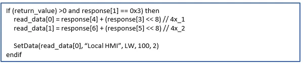
According to the MODBUS RTU protocol specification, the correct response[1] must be equal to 0x03. After getting correct response, calculate the data of 4x_1 and 4x_2 and put in the data into LW-100 and LW-101 of HMI.
The complete macro is as follows:
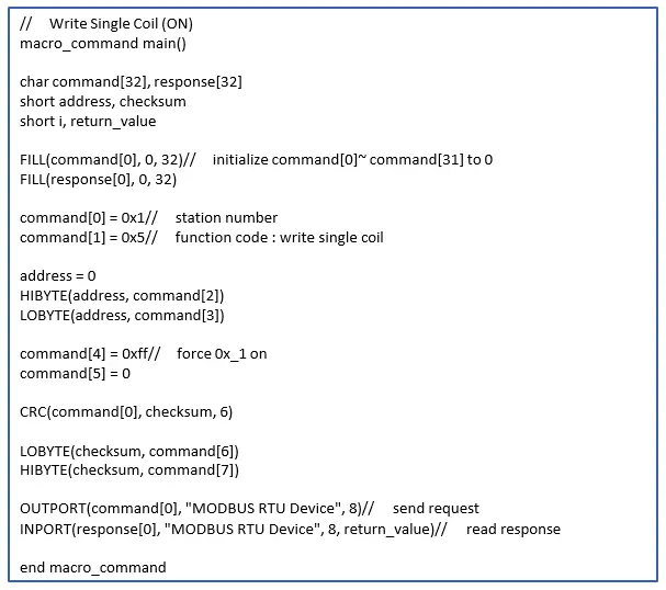
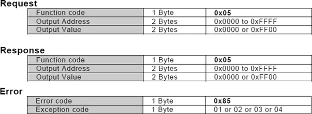
The following example explains how to design a request to set the status of 0x_1. The request uses ”Write Single Coil(0x5)” command.
The complete macro is as follows: