Simulating IEC 61131-3 Logic on a PC
In addition to monitoring logic as it is executed in a device, MAPware-7000 can execute the logic on the development PC using simulation mode.
To simulate a particular logic block, open that block, then select Mode > Start Simulation > Logic Only. The open logic block will be displayed with live values shown for each tag. The appearance of the logic block will vary according to which language type is being simulated.
Simulating Ladder Diagram
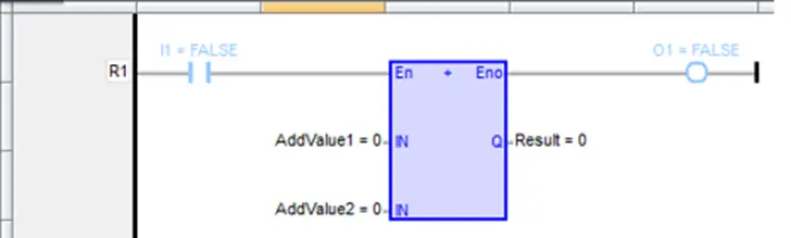
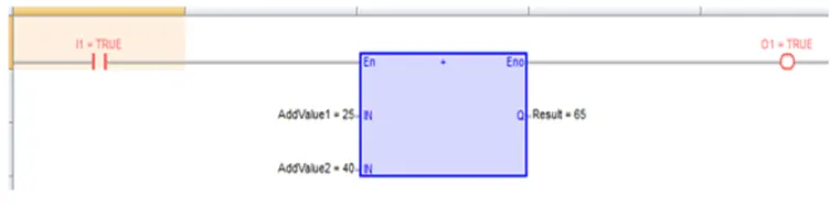
When simulating LD logic blocks, the current value of variables used as inputs are shown next to the tag where they appear in the logic. Contacts and coils are shown color-coded red for true and blue for false:
Simulating Function Block Diagram
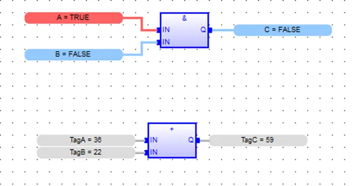
Function Block Diagram Blocks are also shown with tag values next to the tag labels. For boolean values, true is color-coded red and false is blue.
Simulating Structured Text
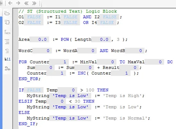
In structured text logic blocks, you must toggle the Show Value in Text quick select button to show current values for variables:
Simulating Instruction List
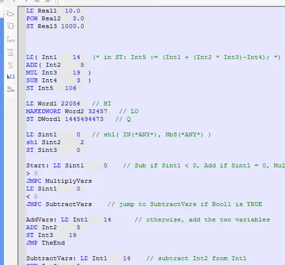
Instruction list blocks appear similarly to Structured Text blocks in the simulator. Again, the Show Value in Text button must be pressed to display the live values.
Controlling Values in the Simulator
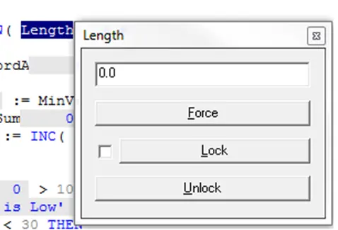
No matter which language is used, values can be manipulated in the simulator window. To change a value simple double-click the tag or element to get an entry box: