Introduction
The HMC2000 and HMC4000 HMI + PLC Series supports the following I/O expansion modules. These modules provide digital and/or analog I/O (inputs and outputs) for an electrical control system. All of the I/O Modules are CE and UL Certified.
| I/O Module Part Number | Description |
|---|---|
| HMC3-M0808Y0401T V2 | 8 Digital Inputs (2 high speed pairs, up to 200kHz) 8 Digital Outputs (6 Relay, 2 PWM up to 200kHz) 4 Analog Inputs (Voltage: 0-5V, 0-10V Current: 0-20mA, 4-20mA, Thermocouple, RTD) 1 Analog Output (Voltage: 0-5V, 0-10V Current: 0-20mA, 4-20mA) |
| HMC3-M1212P0200 V2 | 12 Digital Inputs (2 high-speed pairs, up to 200kHz) 12 Digital Outputs (1 PWM, up to 1kHz) 2 Analog Inputs (Voltage: 0-5V, 0-10V Current: 0-20mA, 4-20mA) |
| HMC3-M1212Y0200 V2 | 12 Digital Inputs (2 high-speed pairs, up to 200kHz) 12 Digital Outputs (10 Relay, 2 PNP w/ 1 PWM up to 1kHz) 2 Analog Inputs (Voltage: 0-5V, 0-10V Current: 0-20mA, 4-20mA) |
| HMC3-M1210P0201 V2 | 12 Digital Inputs (2 high-speed pairs, up to 200kHz) 10 Digital Outputs (1 PWM up to 1kHz) 2 Analog Inputs (Voltage: 0-5V, 0-10V Current: 0-20mA, 4-20mA) 1 Analog Output (Voltage: 0-5V, 0-10V Current: 0-20mA, 4-20mA) |
| HMC3-M1210Y0201 V2 | 12 Digital Inputs (2 high-speed pairs, up to 200kHz) 10 Digital Outputs (8 Relay, 2 PNP w/ 1 PWM, up to 1kHz) 2 Analog Inputs (Voltage: 0-5V, 0-10V Current: 0-20mA, 4-20mA) 1 Analog Output (Voltage: 0-5V, 0-10V Current: 0-20mA, 4-20mA) |
| HMC3-M1614Y V2 | 16 Digital Inputs (2 high-speed pairs, up to 200kHz) 14 Digital Outputs (12 Relay, 1 PWM, up to 1kHz)) |
| HMC3-M1616P V2 | 16 Digital Inputs (2 high-speed pairs, up to 200kHz) 16 Digital Outputs (1 PWM, up to 1kHz) |
I/O Expansion Module Overview
Each I/O terminal is labeled for easy identification on the modules. ‘COM’ is the common ground terminal. A terminal with an ‘X’ followed by a number is an input terminal and a terminal with a ‘Y’ followed by a number is an output terminal. The number refers to the position associated with each terminal on the I/O module.
When a project is created in MAPware-7000, bit/register memory addresses are assigned for each terminal on the expansion module. MAPware-7000 provides the option to allow the software to do this automatically. In this case, it will assign memory addresses according to the position and expansion slot in which the I/O module is located.
In addition, many of the I/O modules have a two-pin connector that is used to connect a voltage source (usually +24VDC). This voltage source drives the output terminals of the I/O modules.
Installing I/O Modules
The expansion modules for the HMC2000 and HMC4000 base units attach onto the back of the unit via expansion slots and are secured with a Phillips screw on the top-right and bottom-left corners of the module. The 4.3” screen supports one expansion module. The 7” screen supports up to three modules, while the 10.1” unit supports up to five modules. Modules connected to the 4.3” unit are attached horizontally to the rear housing, while the 7” and 10.1” units allow for vertical mounting of the modules to the rear housing.
Configuring the I/O Modules
The I/O expansion modules for the HMC2000 and HMC4000 Series are assigned to the proper slot using MAPware-7000. Note that any project downloaded into a HMC base unit with modules that do not match the physical configuration of the unit will not run. Therefore, it is important to correctly identify the I/O modules in the MAPware-7000 project.
Instructions: Configuring the I/O Modules
Create New Project
Open a new project and select the appropriate HMC2000 or HMC4000 model. Click OK.Find the Expansion Folder
In the Project Information Window, click the IO Allocation folder, then click the Expansion folder.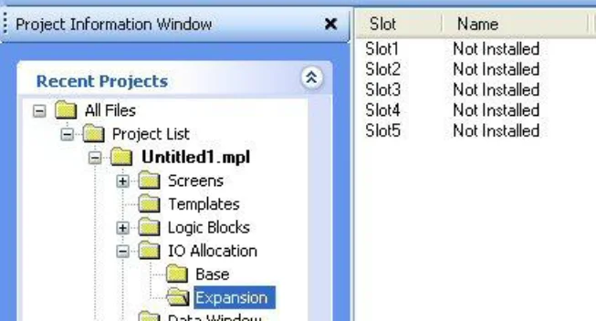
Select the Slot
Double-click Slot 1 to display the IO Allocation dialog: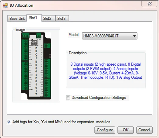
Choose the IO Module
Select the particular I/O expansion module installed in Slot 1 of the HMC base unit from the drop-down Model selection menu. When the checkbox to ‘Add tags for XW, YW, and MW’ option is checked, MAPware-7000 automatically assigns tags to the Tag Database for the I/O module. The tags configured are based upon the module and the slot location. Click OK to close the IO Allocation window, or click the Configure button to pre-configure the module’s input and output channels.View the tags
In this example, Slot 1 is identified with an I/O module, along with a description and memory address allocation. The tags are available in the Tag Database as seen below. These tags can be used in the project to address the I/O, or they can be preconfigured.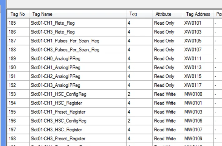
Optional Pre-Configuration
If pre-configuring the I/O modules, simply choose the appropriate Digital or Analog tab and set the respective parameters of each input/output channel to your desired specifications. This will allow configuration of the I/O module automatically, without the need to configure the module elsewhere in the project, such as from a window or via a power-up task. The available options will depend on the module being configured. Select the channel and desired configuration, then click the Confirm button to save the configuration.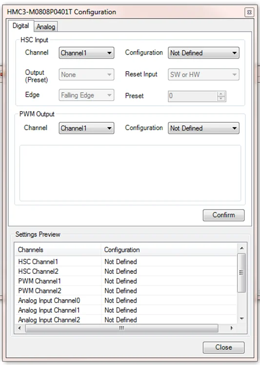
Digital Config Options
The image below lists the digital configuration options for this specific module: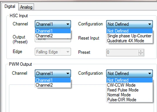
Analog Config
For the Analog configuration of this module, the behavior is the same; choose the channel and the configuration, then click the Confirm button to complete the configuration.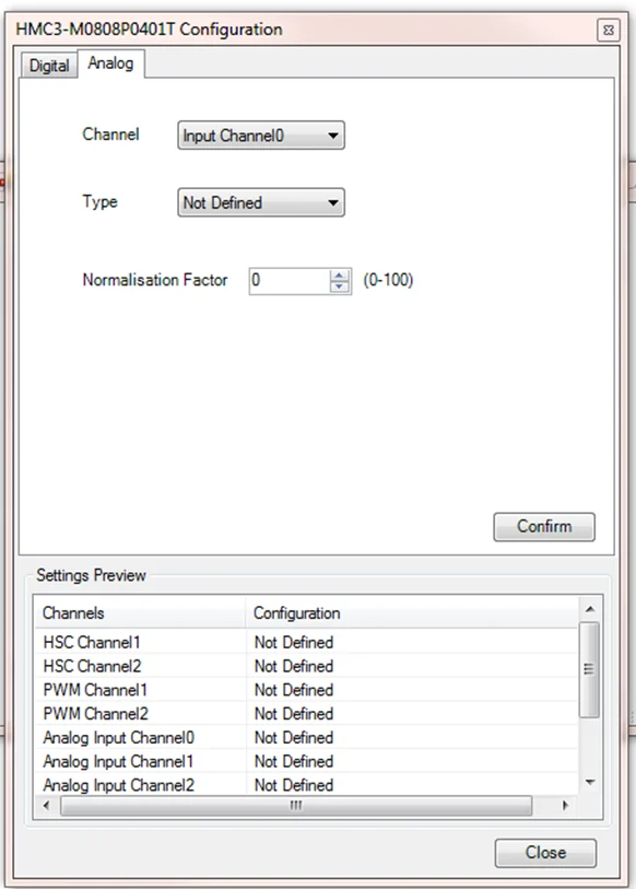
Analog Config Options
Options for the Analog configuration of this specific module: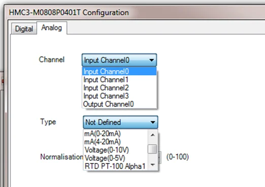
Common Terms and Definitions
This section defines some common terms used to describe various types of inputs and outputs. The terms explained below are generic descriptions. Be sure to consult the datasheet for the specific requirements when installing and wiring a module.
Digital Inputs and Outputs
Digital inputs provide physical connections and interpretations of input devices using discrete signals. The input is represented in the PLC input registers as a 1 for the on state and 0 for the off state. Each digital input terminal is associated with an internal Input Coil (X) in the tag database of the HMC. Similarly, each digital output terminal is associated with an Output Coil (Y).
Analog Inputs and Outputs
Analog inputs provide physical connections and interpretations of input devices using analog signals. The input range depends on the type of input device. Configure analog inputs to work with current or voltage sources. Each analog input terminal is associated with an internal Input Register (XW) in the tag database of the HMC IO module. Similarly, each analog output terminal is associated with an Output Register (YW).
Sinking versus Sourcing
These terms refer to the type of digital inputs or outputs used. A sourcing I/O provides a voltage source, and a sinking I/O provides a ground. Any module that is not bidirectional (meaning current can go in either direction) requires that the circuit conduct current in a specific direction. In order to have current flow, each I/O terminal on the expansion module must have a return path or a signal ground connection. In most modules, multiple I/O terminals share the signal ground connection.
For a sourcing module, the current flows out of the expansion module terminal and into the common (signal ground) terminal. The term source indicates the terminal on the expansion module provides the current to the switch contact or load. For a sinking module, the current flows into the expansion module terminal and out of the common terminal on the I/O module. The term sink indicates the terminal takes in the current from the switch contact or load.
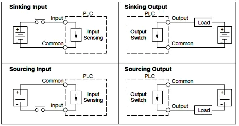
Note: Arrow indicates current flow direction
Digital Outputs (PNP or NPN type)
The output terminals of a digital I/O module use an optically isolated PNP or NPN transistor to energize the connected load. PNP/NPN outputs are faster than relay outputs but can only work with low current DC loads (typically 500mA max per terminal). PNP modules are sourcing modules, and NPN modules are sinking modules.
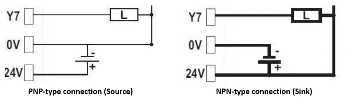
Note: the above diagrams show that a PNP output is ‘sourcing’ current and the NPN output is ‘sinking’ current.
Digital Outputs (Relay type)
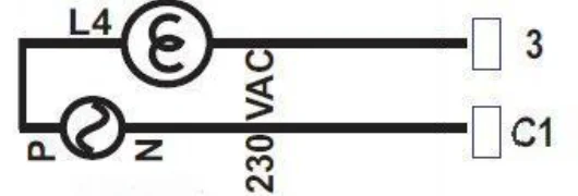
The output terminals of a relay-type digital module typically control loads that require an AC power source.
Use a Relay Output module to connect a DC load that requires more current than the maximum available when using a PNP or NPN output. For AC loads, each relay output contact can handle up to 230VAC with a 2A load per contact. For DC loads, each relay output contact can handle a 2A load per contact for up to 30VDC.
Analog Voltage
Analog voltage inputs can measure DC voltage ranges of 0-5 and 0 to 10 volts. With analog inputs, the analog module writes a data value to the assigned register (XW) based upon the measured DC voltage at the input. Analog outputs can provide 0 to 5VDC and 0 to 10 VDC with a minimum resistance of 1000 ohms depending upon the value in the assigned register (YW). Input resolution is 16-bits and Output resolution is 12-bits.
Analog Current
Analog current inputs can measure DC current ranges from 0 to 20mA and 4 to 20mA. With analog inputs, the analog module writes a data value to the assigned register (XW) based upon the measured DC current at the input. The analog outputs can provide 0 to 20mA and 4 to 20mA. Analog outputs can deliver a DC current of up to 20mA to a load with a maximum resistance of 500 ohms based upon the data value in the assigned register (YW). Input resolution is 16-bits and Output resolution is 12-bits.
Configuring High-speed Counters
Maple Systems’ HMC modules have built-in High-Speed counters that link directly to specific inputs and outputs. Specific registers and bits are predefined for setup and control of these counters. No logic is required to run the counters, other than logic that may be used for configuration and control.
Two inputs on the module are used as the Triggers for the High-Speed counters, and two outputs are used as the Done bits. The inputs support a maximum speed of 200 KHz.
The following bits and registers are associated with a High-Speed counter:
| Register/Bit | Description |
|---|---|
| Configuration Register | The 16-bit register that controls how the High-Speed counter operates. |
| Current Count Register | The 32-bit register that counts the number of times that the Trigger has transitioned. The specified register is the Least Significant Word (LSW); the next consecutive register is the Most Significant Word (MSW). |
| Preset Register | The 32-bit register that defines the number of counts at which the Done bit will be set (see description of Done Bit below). The specified register is the Least Significant Word (LSW); the next consecutive register is the Most Significant Word (MSW). |
| Trigger Bit | The input bit that triggers the count. The counter will increment by one on each bit transition. The counter can operate on a falling (default) or rising edge. |
| Enable Bit | The counter will not run unless this bit is set. If this bit is reset while the counter is running, the current values will be maintained, but the Trigger bit will have no effect. The Done bit is reset if the Enable bit is reset. If the Current Count value is greater than or equal to the Preset value, the Done bit is set after the Enable bit is set again. |
| Reset Bit | When this bit goes from false to true, the current count will reset to 0 and the Done bit is reset. The reset occurs even when the Enable bit is reset. The reset is accomplished by an internal bit or a physical input. |
| Done Bit | The physical output that turns on when the Current Count is equal to or greater than the Preset value. The bit remains set until the Reset bit goes true, even if the counter counts beyond the preset. If the Enable bit is reset, the Done bit will reset. If the Enable bit is set while the Current Count is equal to or greater than the Preset, the Done bit is set. |
Reference the tables below when configuring each HSC Configuration Register:
| Input Mode | Output Mode | Register Value |
|---|---|---|
| Normal Input | N/A | 0 |
| High Speed, Single Phase, Up/Down Counter | Output ON when preset is reached | 2 |
| High Speed, Single Phase, Up/Down Counter | Output ON when counter is enabled, OFF when preset is reached | 258 |
| Quadrature 4X | Output ON when preset is reached | 131 |
| Quadrature 4X | Output ON when counter is enabled, OFF when preset is reached | 387 |
HSC Configuration Register Bit table
| Bits | Function |
|---|---|
| 15-12 | Not used |
| 11-10 | 00: Reset counter if SW Reset bit or physical I/Preset bit goes from 0 to 1 01: Reset counter if the SW reset bit goes from 0 to 1 11: reserved for future use |
| 9 | Forced Output Configuration 0: Forced output ON for Preset 1 1: Forced output ON when enabled and OFF when Preset 1 reached |
| 8 | Forced Output Control 0: Forced Output Disabled 1: Forced Output Enabled |
| 7-6 | Quadrature mode 00: Reserved 01: Reserved 010: 4X Quadrature mode |
| 4-5 | HSC 00: Single Phase Up counter |
| 3 | 0: Falling Edge 1: Rising Edge |
| 2, 1, 0 | Module Operating Mode 000: Normal Operation 010: Up Counter HSC 011: Quadrature |
To Implement High-speed Counter Operation
Instructions: To Implement High-speed Counter Operation
Connect HSC Source
Connect a device that will provide the high-speed pulses to one of the high-speed inputs on the expansion module.HSC Config
Configure the HSC using the I/O Allocation > Expansion window, assign your I/O module to the slot, and press “Configure”.You can also write to the configuration register value using the Power-Up logic block or in a Power-Up Task.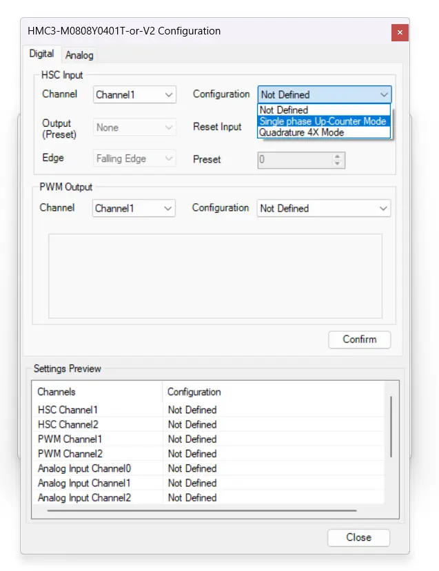
Preset Count
Write the HSC preset count value in that channel’s Preset Register.Enable
Enable the HSC by setting the HSC Enable Bit for that channel.HSC Operation
HSC increments the current value register for that channel until the preset value is reached.Enable Reset
Enable the HSC Reset Bit for that channel. This will cause the HSC current value to reset back to 0.Clear and start again
To start the process again, simply reset (clear) the HSC Reset Bit and set the HSC Enable Bit.If the HSC Enable Bit is still ON, you must reset (clear) this bit, and then set it again.
Specific High-Speed Counter Registers
The registers and I/O associated with the High-Speed Counter can be found below.
| Function | Counter 1 (Channel 0) | Counter 2 (Channel 1) |
|---|---|---|
| Trigger Bit | Xnn000 | Xnn002 |
| Enable Bit | Mnn080 | Mnn176 |
| Reset Bit | Mnn081 | Mnn177 |
| Configuration Register | MWnn00 | MWnn06 |
| Current Count Register (LSW, MSW) | MWnn01, MWnn02 | MWnn07, MWnn08 |
| Preset Register (LSW, MSW) | MWnn03, MWnn04 | MWnn09, MWnn10 |
Note: nn is the slot in which the module is installed (slot 1 is 01, slot 2 02, etc.)
For example, a module installed in Slot 3 has the following assignments:
| Function | Counter 1 (Channel 0) | Counter 2 (Channel 1) |
|---|---|---|
| Trigger Bit | X03000 | X03002 |
| Enable Bit | M03080 | M03176 |
| Reset Bit | M03081 | M03177 |
| Configuration Register | MW0300 | MW0306 |
| Current Count Register (LSW, MSW) | MW0301, MW0302 | MWnn07, MW0308 |
| Preset Register (LSW, MSW) | MW0303, MWnn04 | MW0309, MW0310 |
Pulse Width Modulation (PWM) Outputs
Maple Systems’ HMC3000 I/O modules have built-in Pulse Width Modulation functionality. Specific registers and bits are predefined for setup and control of these functions. No logic is required to run the PWM, other than logic that may be used to configure and control them.
There are four modes of PWM: Normal, CW/CCW, Pulse/Direction and Fixed Pulse. Use the information below to configure the desired PWM output mode.
Note: For each table below, nn is the slot in which the module is installed (slot 1 is 01, slot 2 02, etc.)
Normal PWM
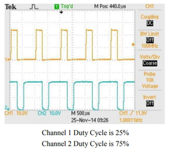
The frequency must be the same for channel 1 and channel 2, but the Duty Cycle is independently adjustable for each channel. Duty Cycle can be adjusted while the output is running. The valid range is 0 to 100%, but the effective range will vary depending on the device being controlled. The frequency can be adjusted while running (place a 2 in the Config register). The Channel 1 and Channel 2 outputs can be enabled and disabled independently.
| Function | Register | Register | Description |
|---|---|---|---|
| Output, PWM Pulse | Y0 (Channel 1) | Y1 (Channel 2) | Physical Output |
| Configuration Register | MWnn24 | MWnn30 | Value = 1 for this mode |
| Frequency Setting Register | MWnn25 | MWnn31 | Range = 1 to 200000 |
| ON Duty Setting Register (Duty Cycle) | MWnn27 | MWnn33 | Range = 0 to 100 |
| Pulse Enable Flag | Mnn576 | Mnn577 | Output enabled when ON |
| ON Duty Setting Error Flag | Mnn466 | Mnn471 | ON = error (resets automatically) |
| Frequency Setting Error Flag | Mnn467 | Mnn472 | ON = error (resets automatically) |
CW/CCW (Clockwise/Counter Clockwise)
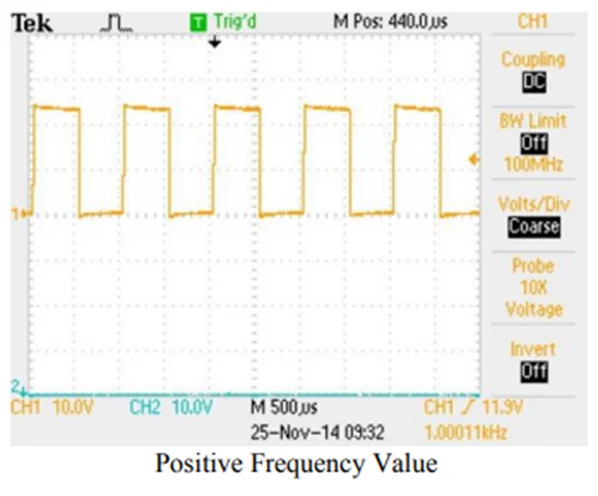
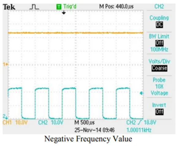
When the frequency is positive, the output signal is generated on Channel 1, and Channel 2 is not used. When the frequency value is negative, the output signal is generated on Channel 2, and Channel 1 is not used. The frequency can be adjusted while running (place a 4 in the Config register instead of 3), and the Duty Cycle is fixed at 50%.
| Function | Register | Register | Description |
|---|---|---|---|
| Output, PWM Pulse | Y0 (Channel 1) | Y1 (Channel 2) | Physical Output |
| Configuration Register | MWnn24 | MWnn30 | Value = 3 for this mode |
| Frequency Setting Register | MWnn25 | MWnn31 | Range = -100000 to -1 and 1 to 100000 |
| Pulse Enable Flag | Mnn576 | Mnn577 | Output enabled when ON |
| Frequency Setting Error Flag | Mnn467 | Mnn472 | ON = error (resets automatically) |
Pulse/Direction
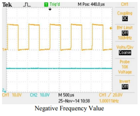
The output signal is generated on Channel 1. If the frequency value is positive, Channel 2 is held low. If the frequency value is negative, Channel 2 is held high. The frequency can be adjusted while running (place an 8 in the configuration register), and the Duty Cycle is fixed at 50%.
| Function | Register | Register | Description |
|---|---|---|---|
| Output, PWM Pulse | Y0 (Channel 1) | Y1 (Channel 2) | Physical Output |
| Configuration Register | MWnn24 | MWnn30 | Value = 7 for this mode |
| Frequency Setting Register | MWnn25 | MWnn31 | Range = -100000 to -1 and 1 to 100000 |
| Pulse Enable Flag | Mnn576 | Mnn577 | Output enabled when ON |
| Frequency Setting Error Flag | Mnn467 | Mnn472 | ON = error (resets automatically) |
Fixed Pulse Mode
The output signal is generated on Channel 1. The frequency ramps up from the minimum frequency to the maximum frequency in the interval specified by acceleration time. The output signal is generated until the specified number of pulses has been sent. As the number of pulses approaches the specified count, the frequency ramps down from the maximum frequency to the minimum frequency in the interval specified by the deceleration time. When the specified number of pulses is reached, the output signal stops but remains enabled. The Duty Cycle is fixed at 50%.
| Function | Register | Register | Description |
|---|---|---|---|
| Output, PWM Pulse | Y0 (Channel 1) | Y1 (Channel 2) | Physical Output |
| Configuration Register | MWnn24 | MWnn30 | Value = 9 for this mode |
| Minimum Frequency Register | MWnn25 | MWnn31 | Range = 1 to 100000 |
| Maximum Frequency Register | MWnn27 | MWnn33 | Range = 1 to 100000 |
| Acceleration Time Register | MWnn37 | MWnn38 | Range: 0 to 65535 |
| Deceleration Time Register | MWnn39 | MWnn40 | Range: 0 to 35536 |
| Total Pulses Register | MWnn41 | MWnn43 | 0 to 4294967295 |
| Elapsed Pulses Register | MWnn45 | MWnn47 | 0 to 4294967295 |
| Pulse Enable Flag | Mnn576 | Mnn577 | Output enabled when ON |
| Frequency Setting Error Flag | Mnn467 | Mnn472 | ON = error (resets automatically) |
| Acceleration Time Error Flag | Mnn468 | Mnn473 | ON = error |
| Deceleration Time Error Flag | Mnn469 | Mnn474 | ON = error |
| Total Pulses Setting Error Flag | Mnn470 | Mnn475 | ON = error |
| Total Pulses Reached | Mnn784 | Mnn785 | ON when Total Pulses have been sent |