
Keypads
Keypads on the HMC4000
The HMC4000 only allows for popup keypads, which are pre-configured for each keypad use case. The options are limited to “Show Display Range” of each keypad, but otherwise they should appear how they should and function normally.
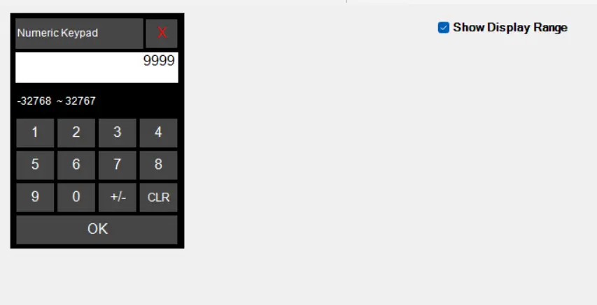
The rest of this page will describe how keypads function on the HMC2000s
Popup Keypads
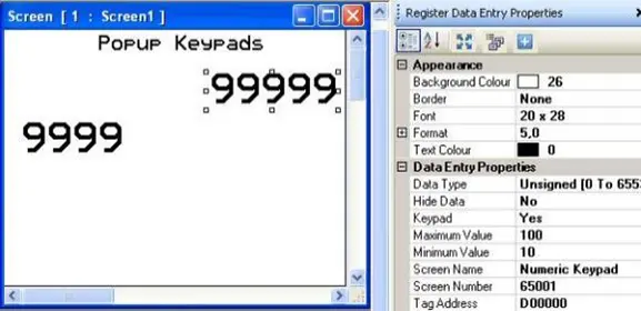
A popup keypad is any keypad that appears automatically when you click into a Numeric Entry Object. To get the popup keypad to appear, you must enable the Keypad option in the Data Entry Properties section of the Numeric Entry object.
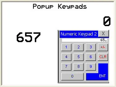
During operation, simply touch the Numeric Entry object. This will cause your popup keypad to display immediately in the upper left corner of the display. The current value of the target register shows in the entry area.
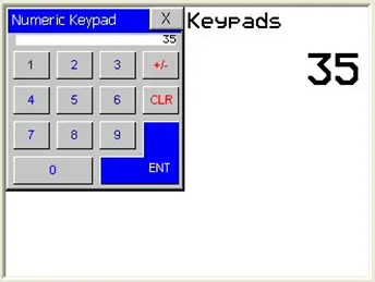
Use the keypad to enter a new number, then press the ENTER key. The new value writes to the target register and the popup keypad disappears. Pressing the close window icon on the keypad removes the keypad without making any changes to the value.
- Note: there is no way to move the popup keypad to a new location on the screen once displayed. Therefore, if you wish to have the keypad appear in a different location when called, create a new keypad and use the X, Y coordinates of the screen to place the keypad at the location you desire.
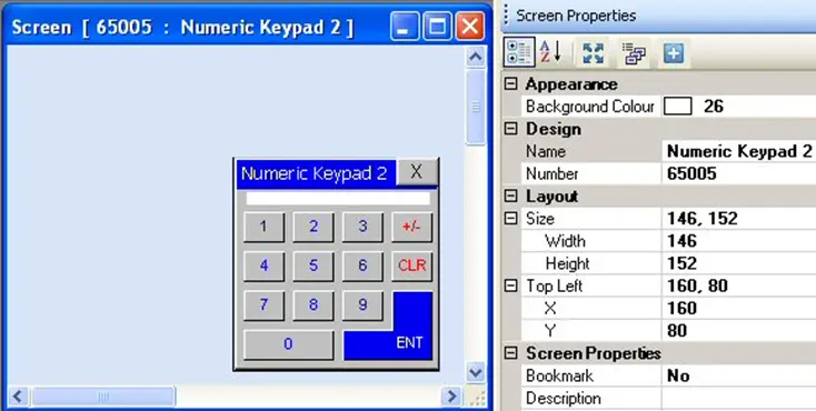
Then reference this keypad in the Register Data Entry Properties dialog box of the target register in the Screen Name/Number attribute fields.
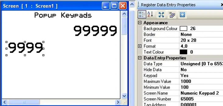
During operation, the popup keypad appears in the desired location:
On Screen Keypads
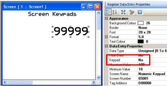
Rather than use the popup keypad feature, there may be an instance where you would prefer to have the keypad always shown (perhaps to make it obvious to the operator that entry is allowed). To use an on-screen keypad, first disable the popup keypad option in the Numeric Entry object by selecting No in the Keypad field.
Next, place one of the predefined keypads (see sections below) or a custom keypad of your own design on the screen.
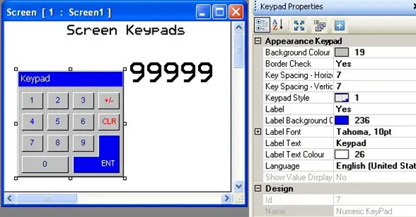
During operation, using an on-screen keypad differs slightly from using a popup keypad. To initiate entering a new number simply click anywhere on the keypad not on the Numeric Entry Object. This causes the last digit of the Numeric Entry object to blink with an underline, indicating that you are now in ‘entry’ mode.
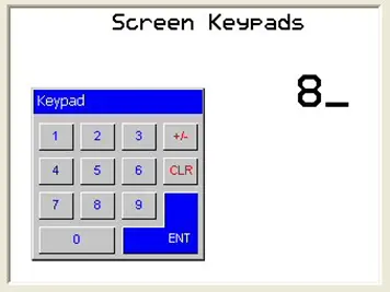
Use the keypad to enter the new number, then press the ENTER button to send the new value to the target register. If you wish to cancel the entry, you must first click the Clear (CLR) button, then press the ENTER button.
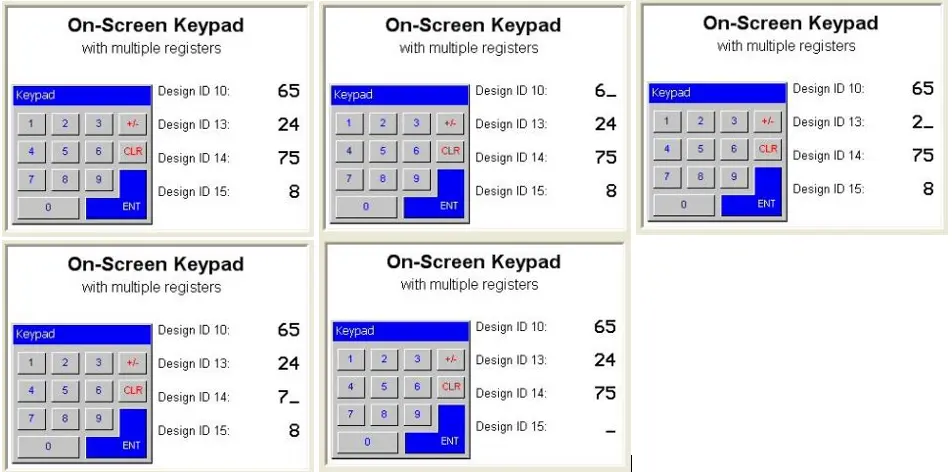
If you have multiple Numeric Entry objects on the same screen, and you are using an on-screen keypad, the keypad will target each object in sequence, starting with the object that has the lowest Design ID number assigned during project configuration.

Predefined Numeric Keypads
The MAPware software offers many predefined numeric keypads that popup when using a Numeric Entry or Bit Entry object or can also display on screen. These keypads offer various styles to customize for the particular needs of the project.
How to place a Numeric Keypad object on a screen
- Use one of the following:
- click Draw > Input Objects > Keypad from the standard menu
- click Advanced Objects > Keypad from the Draw toolbar
- Move cursor to a start point for the upper left corner of the keypad object. Click the mouse cursor to place the object onto the screen.
- The keypad appears on screen and the Keypad Properties box displays.
Options available using the Keypad Properties dialog box
- Background Color (description) – option to select a color as a ‘backdrop’ to the object.
- Border Check (description) – add a line around the perimeter of the object.
- Font (description) – select from one of four options – 5×7, 7×14, 10×14, and 20×28 pixels.
- Key Spacing Horizontal – this attribute determines the number of pixels between each key along the horizontal axis. Range is 6 to 43 pixels.
Note: the overall width of the keypad determines the width of each key. Therefore, to adjust the size of the keys, you must change the size of the overall keypad. - Key Spacing Vertical – this attribute determines the number of pixels between each key along the vertical axis. Range is 6 to 49 pixels.
Note: the overall height of the keypad determines the height of each key. Therefore, to adjust the size of the keys, you must change the size of the overall keypad. - Keypad Style – there are eight options to the arrangement of the numeric keys:
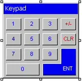
Standard 10-key entry pad with negative entry key (default)
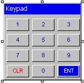
Standard 10-key entry pad
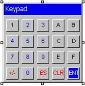
Hexadecimal entry pad with negative entry key
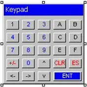
Hexadecimal entry pad with digit entry keys
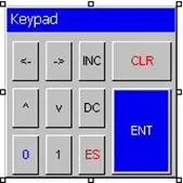
Increment/Decrement entry pad
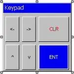
Simple increment/decrement by digit entry pad with Clear key
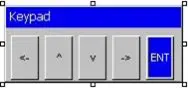
Simple increment/decrement by digit entry pad
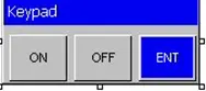
On/Off entry pad
- Label (description) – option to have a label appear on the top/bottom of the object.
- Label Background Color – select the background color. Click to display the color palette.
- Label Font – configure how you wish the label text to appear
- Label Text – the text that appears in the label. Maximum of 21 characters allowed.
- Label Text Color – select the label text color. Click to display the color palette.
- Language (description) – highlight the language that must be selected to display the entered text.
- Show Value Display – this option is set to ‘No’ and cannot change.
- Design (description) – identifies object..
- Keys Properties – select the ‘style’ and function of selected key.
- Back Color – select the background color of the button. Click to display the color palette.
- Display Text – option to display text on the button.
- Keypad Key Task – select from the pull-down list box which function (i.e. display a number, control key, etc.) the selected button has:
- Numeric Key 0-9, A-F – used to enter decimal and/or hexadecimal numbers.
- Shift Value to Left – essentially this multiplies the value by 10 each time this key is pressed.
- Move Cursor to Left, Move Cursor to Right keys – use these keys to move the focus cursor to the left or right by one digit. This allows you to change each digit of a number during entry without the need to clear the entry and start over.
- Increase Digit by 1, Decrease Digit by 1 keys – these keys will increment or decrement the digit that is currently highlighted by the focus cursor.
- Note: if digit 0 is displayed, pressing the Decrease by 1 key will change this digit to 9. Similarly, if digit 9 is displayed, pressing the Increase Digit by 1 key will change the digit from 9 to 0.
- Increase Value by 1, Decrease Value by 1 keys – these keys will increment or decrement the value or number that is currently entered by one.Sign Key (+/-) and Sign Key (+/-) and 0 keys – use these keys to change the sign (positive or negative) of the number entered. The Sign Key with 0 adds a little twist – if the key is pressed more than once, it will add 0s to the right of the number entered.
- Note: for these keys to work, you must use configure the target Numeric Entry register with Data Type of Signed.
- Clear Data Entry – when pressed, this key clears the entire entry and starts over.
- Cancel Data Entry – this key exits data entry mode without making any changes to the value of the target register.
- Accept Data Entry – this key writes the entered keypad value to the target register.
- Switch to Next Data Entry – if you have multiple Numeric/Coil Entry registers on the screen, this key will move the focus of the keypad between registers.
- Turn Bit On, Turn Bit Off keys – use these keys to set (1) or clear (0) a Bit Data register.
- Style Index (description) – selects a style or ‘look’ to the button

Standard Key – Example:


Large Key – Example:
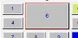

Corner Key – Example:
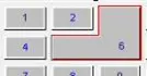

Double Key – Example:
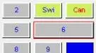
- Text – the text that appears in the button. The overall size of the keypad and the font used determines the maximum number of characters.
- Text Color – determines the color of the text. Click the ellipses to display the color palette.
- Layout (description) – coordinates (i.e. size and position) for the object.
Resize a Keypad object
Move the mouse pointer over one of the resize handles. When the pointer changes to a double-headed arrow, simply click and drag to a new location.
- Note that if you resize the keypad to a point at which the buttons are too small, then an error message displays.

Predefined ASCII Keypads (Alphanumeric)
The MAPware software offers two predefined ASCII keypads that popup when using a Numeric Entry or Bit Entry object or can display on screen. These keypads offer various styles to customize for the particular needs of the project.
How to place an ASCII Keypad object on a screen
- Use one of the following:
- click Draw > Input Objects > ASCII Keypad from the standard menu
- click Advanced Objects > ASCII Keypad from the Draw toolbar
- Move cursor to a start point for the upper left corner of the keypad object. Click the mouse cursor to place the object onto the screen.
- The keypad appears on screen and the ASCII Keypad Properties box displays.
Options available using the ASCII Keypad Properties dialog box
- Background Color (description) – option to select a color as a ‘backdrop’ to the object.
- Key Spacing Horizontal – this attribute determines the number of pixels between each key along the horizontal axis. Value is set to 2 and cannot be changed.
- Note: the overall width of the keypad determines the width of each key. Therefore, to adjust the size of the keys, you must change the size of the overall keypad.
- Key Spacing Vertical – this attribute determines the number of pixels between each key along the vertical axis. Value is set to 2 and cannot be changed.
- Note: the overall height of the keypad determines the height of each key. Therefore, to adjust the size of the keys, you must change the size of the overall keypad.
- Keypad Style – there are two options to the arrangement of the numeric keys:
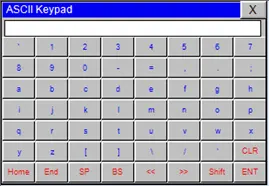
Standard 7×8 (56 keys) with upper/lower case (default)
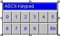
10-Key Entry Pad
- Label (description) – option to have a label appear on the top/bottom of the object.
- Label Background Color – select the background color. Click to display the color palette.
- Label Font Color – select the label text color. Click to display the color palette.
- Label Text – the text that appears in the label. Maximum of 21 characters allowed.
- Language (description) – highlight the language that must be selected to display the entered text.
- Show Value Display – this option is set to ‘No’ and cannot change.
- Design (description) – identifies object.
- Keys Properties – select the ‘style’ and function of selected key.
- Key Background Color – select the background color of the button. Click to display the color palette.
- Key Text Color – determines the color of the text. Click to display the color palette.
- Layout (description) – coordinates (i.e. size and position) for the object.
Resize an ASCII Keypad object
Move the mouse pointer over one of the resize handles. When the pointer changes to a double-headed arrow, simply click and drag to a new location.

Creating a Custom Keypad
In addition to the predefined keypads, the custom keypad object allows you to create a keypad specific to your needs.
How to place a Custom Keypad object on a screen
- Use one of the following:
- click Draw > Input Objects > Custom Keypad from the standard menu
- click Advanced Objects > Custom Keypad from the Draw toolbar
- Move cursor to a start point for the upper left corner of the keypad object. Click the mouse cursor to place the object onto the screen.
- The keypad appears on screen and the Custom Keypad Properties box displays.
Options available using the Custom Keypad Properties dialog box
- Design (description) – identifies object.
- Background Color (description) – option to select a color as a ‘backdrop’ to the object.
- Key Spacing Horizontal – this attribute determines the number of pixels between each key along the horizontal axis. Range is 6 to 49 pixels.
- Note: the overall width of the keypad determines the width of each key. Therefore, to adjust the size of the keys, you must change the size of the overall keypad.
- Key Spacing Vertical – this attribute determines the number of pixels between each key along the vertical axis. Range is 6 to 49 pixels.
- Note: the overall height of the keypad determines the height of each key. Therefore, to adjust the size of the keys, you must change the size of the overall keypad.
- Keypad Type – there are two options to the type of keypad used. Numeric is for data entry and ASCII is for entering alphanumeric characters.
- Label (description) – option to have a label appear on the top/bottom of the object.
- Label Background Color – select the background color. Click to display the color palette.
- Label Font Color – select the label text color. Click to display the color palette.
- Label Text – the text that appears in the label. Maximum of 21 characters allowed.
- Language (description) – highlight the language that must be selected to display the entered text.
- No. of Columns – select the number of key button columns. Range is 1 to 10.
- No. of Rows – select the number of key button rows. Range is 1 to 10.
- Show Value Display – this option is set to ‘No’ and cannot change
- Keys Properties – When you select a key, you can select the ‘style’ and function of selected key here.
- Key Background Color – select the background color of the button. Click to display the color palette.
- Key Text – option to display text on the button
- Key Text Color – configure the color of the button text. Click to display the color palette.
- Keypad Numeric Key Task – select from the pull-down list box which function (i.e. display a number, control key, etc.) the selected button has (see Numeric and ASCII section for more details).
- Merge Keys – combine two keys together to form one function. This ensures that there is no space between the two keys which, when pressed, does not do anything.
- Show Key – option to make key invisible and inactive
- Show Key Text – option to display the configured Key Text on the button. With this option, you can use the Key Text field to create a description of the button without having the description displayed.
- Layout (description) – coordinates (i.e. size and position) for the object.
Resize a Custom Keypad object
Move the mouse pointer over one of the resize handles. When the pointer changes to a double-headed arrow, simply click and drag to a new location.