
HMC3-M0808Y0401T-V2
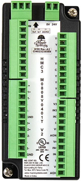
This module is an input/output module for ONLY the HMC2000 and HMC4000 Series models. It has eight bidirectional inputs, two pairs of which are high-speed inputs. It also has eight outputs, two sourcing (PNP) which can be configured for PWM operation and the other 6 are relay type.
This module also has 4 universal analog inputs (Voltage/Current/Thermocouple/RTD) as well as one analog output (Voltage/Current).
[Note: HMC3 I/O Module V2 Series are only compatible with HMC2000/ HMC4000 Series Base Model]
8 Digital Inputs (2 high-speed pairs up to 200kHz)
8 Digital Outputs (6 Relay, 2 PNP w/ 2 PWM up to 200kHz)
4 Universal Analog Inputs
- Voltage: 0-5V, 0-10V
- Current: 0-20mA, 4-20mA
- Thermocouple
- RTD
1 Analog Output
- Voltage: 0-5V, 0-10V
- Current: 0-20mA, 4-20mA
| Specifications | |
| Power | 12V and 3.3VDC from base |
| Certifications | CE, UL |
| Digital Inputs | 8 bidirectional inputs (2 high-speed pairs) |
| Rated Input Voltage | 24 VDC +/- 15% |
| Rated input current | Up to 5mA (per contact) |
| Input impedance | 4.9K ohms |
| Minimum ON voltage | 15 VDC |
| Maximum OFF voltage | 5 VDC |
| Turn ON Time | 10 mSec |
| Turn OFF Time | 10 mSec |
| Isolation | Optically isolated from internal circuit |
| Analog Inputs | 4 Inputs, each configurable as: 0 to 50mV, 0 to 100 mV; 0 to 10V, 0 to 5V; 0 to 20mA, 4-20mA; PT100 RTD, alpha1 [0.00385 Ω/Ω°C] (-200 to 850 C); PT100 RTD, alpha2 [0.003926 Ω/Ω°C] (-100 to 457 C); PT1000 RTD (-200 to 850 C); Type J Thermocouple (-210 to 1200 C); Type K Thermocouple (-200 to 1373 C) | |
| Input Resolution | 16 bit | |
| Input Impedance | 3 KΩ | |
| Input Accuracy | Overall Accuracy 0.2% of full scale@25°C (max) | |
| Digital Outputs | 8 outputs: 6 Relay, 2 Sourcing (PNP-type) / 2 PWM | |
| Maximum PWM Output Frequency | 200KHz | |
| Minimum ON Output Voltage | 22 VDC | |
| Maximum ON Output Voltage | 30 VDC | |
| Minimum OFF Output Voltage | 0.2 VDC | |
| Maximum OFF Output Voltage | 1 VDC | |
| Rated Load | 250mA @ 24VDC 2A @230VAC | |
| Nominal load | 96W 6W (resistive) @ 24VDC 6VA (inductive, UPF) | |
| Analog Outputs | 1, configurable as: 0 to 5V, 0 to 10V; 0 to 20mA, 4-20mA | |
| Accuracy | Overall Accuracy 0.2% of full scale@25°C (max) | |
| Load | 1 KΩ (Min) for V; 500Ω (Max) for mA | |
| Output Resolution | 12 bit | |
| High-speed Channels | ||
| No. of inputs | 2 channel pairs (X0/X1 and X2/X3) | |
| Maximum Input Frequency | 200 KHz | |
| Maximum Input Count | 4,294,967,295 (32-bit) | |
| General | ||
| Connection method | Removable terminals (3.81 mm pitch) | |
| Operating Temperature | 0 to 55°C | |
| Operating Humidity | 10% to 90% (non-condensing) | |
| Mechanical Dimension (W x H x D) | 1.88 x 4.25 x 1.61 inches [48x108x41mm] | |
Configuration
Use MAPware-7000 to assign input (X and XW), output (Y and YW) and configuration (M and MW) memory addresses to the module. These addresses are created according to the slot location of the module, where nn refers to the slot number (ex. 01…05):
| Function | Register | Access | |
| X0-X7 Digital Inputs | Xnn000-007 (XWnn00) | Read Only | |
| Y0-Y7 Digital Outputs | Ynn000-007 (YWnn00) | Read/Write | |
| High-speed Counter Option | HSC Channel 1 | HSC Channel 2 | |
| HSC Input Pin | X0 | X2 | Read Only |
| Quadrature Inputs | Pair 1 | Pair 2 | |
| Counter Inputs | X0, X1 | X2, X3 | Read Only |
| HSC Configuration Register | MWnn00 | MWnn06 | Read/Write |
| HSC Counter Register (Current Value) | MWnn01 | MWnn07 | Read/Write |
| HSC Preset Register | MWnn03 | MWnn09 | Read/Write |
| HSC Enable Bit | Mnn080 | Mnn176 | Read/Write |
| HSC Reset Bit | Mnn081 | Mnn177 | Read/Write |
| Output Flag | Y2 | Y3 | |
| PWM Outputs | Channel 1 | Channel 2 | |
| Output | Y0 | Y1 | Read Only |
| PWM Configuration Register | MWnn24 | MWnn30 | Read/Write |
| Frequency Setting Register | MWnn25 | MWnn31 | Read/Write |
| ON Duty Setting Register (Duty Cycle) | MWnn27 | MWnn33 | Read/Write |
| Pulse Enable Flag | Mnn576 | Mnn577 | Read/Write |
| ON Duty Setting Error Flag | Mnn466 | Mnn471 | Read Only |
| Frequency Setting Error Flag | Mnn467 | Mnn472 | Read Only |
| Analog Inputs | Register | ||
| Input Channel 0 Data | XWnn11 | Read Only | |
| Input Channel 1 Data | XWnn13 | Read Only | |
| Input Channel 2 Data | XWnn15 | Read Only | |
| Input Channel 3 Data | XWnn17 | Read Only | |
| Input Channel 0 Config Register | MWnn60 | Read/Write | |
| Input Channel 1 Config Register | MWnn61 | Read/Write | |
| Input Channel 2 Config Register | MWnn62 | Read/Write | |
| Input Channel 3 Config Register | MWnn63 | Read/Write | |
| Analog Outputs | Register | ||
| Output Channel 0 Data (Voltage) | YWnn01 | Read/Write | |
| Output Channel 0 Data (Current) | YWnn02 | Read/Write | |
| Output Channel 0 Config Register | MWnn68 | Read/Write | |
Reference the table below when configuring each HSC Configuration Register:
| Input Mode | Output Mode | Register Value |
| Normal Input | N/A | 0 |
| High Speed, Single Phase, Up/Down Counter | Output ON when preset is reached | 2 |
| Output ON when counter is enabled, OFF when preset is reached | 258 | |
| Quadrature 4X | Output ON when preset is reached | 131 |
| Output ON when counter is enabled, OFF when preset is reached | 387 |
Reference the table below when configuring the PWM Configuration Registers:
| Output Mode | Register Value |
| Normal PWM (fixed frequency) | 1 |
| Normal PWM (variable frequency) | 2 |
| CW/CCW (fixed frequency) | 3 |
| CW/CCW (variable frequency) | 4 |
| Pulse/Direction (fixed frequency) | 7 |
| Pulse/Direction (variable frequency) | 8 |
| Trapezoidal (Fixed Pulse Mode) | 9 |
Reference the table below when configuring each Analog Input Configuration Register (MWnn60-MWnn63):
| Input Signal Type | Register Value |
| Voltage, 0 to 10V | 1 |
| Voltage, 0 to 5V | 6 |
| Voltage, 0 to 50mV | 5 |
| Voltage, 0 to 100mV | 4 |
| Current, 4 to 20mA | 2 |
| Current, 0 to 20mA | 3 |
| RTC and Thermocouple | For °C |
| RTD, PT100, alpha1 1 | 7 |
| RTD, PT100, alpha2 1 | 8 |
| RTD, PT1000 | 9 |
| Thermocouple, Type J 2 | 14 |
| Thermocouple, Type K 2 | 15 |
Notes:
- alpha1= 0.00385 Ω/Ω°C, alpha2=0.003926 Ω/Ω°C
- 15-minute module warm-up time recommended
The values in the appropriate analog input register range from 0-65535.
| Expansion Module Register Value | Input Values | |||||
| 0 to 20mA | 4 to 20mA | 0 to 10V | 0 to 5V | 0 to 100mV | 0 to 50mV | |
| 0 | 0mA | 4mA | 0V | 0V | 0mV | 0mV |
| 16384 | 5mA | 8mA | 2.5V | 1.25V | 25mV | 12.5mV |
| 32768 | 10mA | 12mA | 5V | 2.5V | 50mV | 25mV |
| 49152 | 15mA | 16mA | 7.5V | 3.75V | 75mV | 37.5mV |
| 65535 | 20mA | 20mA | 10V | 5V | 100mV | 50mV |
Reference the table below when configuring the Analog Output Configuration Register (MWnn68):
| Output Signal Type | Register Value |
| Voltage, 0 to 10V | 2 |
| Voltage, 0 to 5V | 1 |
| Current, 4 to 20mA | 5 |
| Current, 0 to 20mA | 6 |
Analog expansion modules have an analog output resolution of 12 bits with values ranging from 0-4095.
| Expansion Module Reg Value | Output Values | |
| 0 to 10V | 4 to 20mA | |
| 0 | 0 | 4mA |
| 1024 | 2.5V | 8mA |
| 2048 | 5V | 12mA |
| 3072 | 7.5V | 16mA |
| 4095 | 10V | 20mA |
Wiring Diagrams
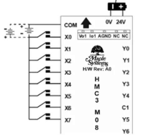
Digital Inputs
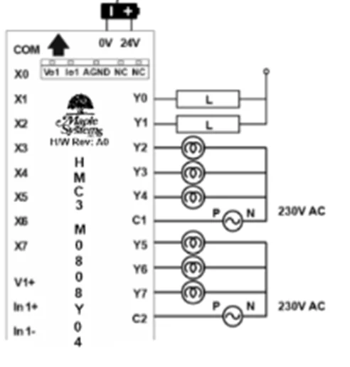
Digital Outputs
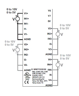
Analog Input: Voltage
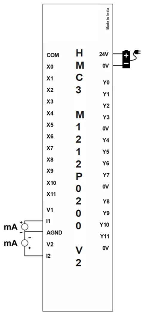
Analog Input: Current
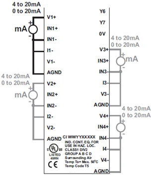
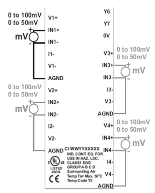
Analog Input: mV / Thermocouple
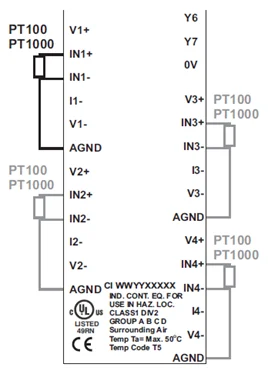
Analog Input: RTD
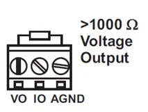
Analog Output: Voltage
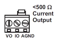
Analog Output: Current
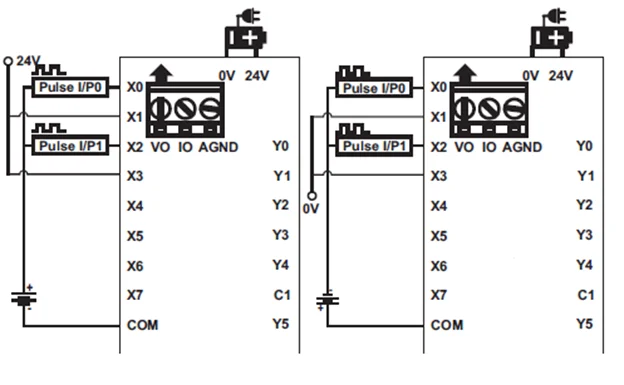
HSC Single Phase Up Counter
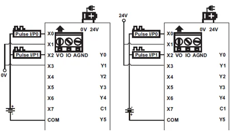
HSC Single Phase Down Counter
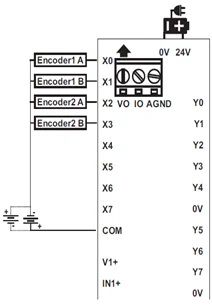
HSC Quadrature
HMC3-M1212P0200 V2
This module is an input/output module for the HMC2000 and HMC4000 Series models. It has twelve digital inputs, two of which are high-speed pairs and 12 sourcing digital outputs. One of those digital outputs are configurable as PWM.
This module also has two analog inputs, each measuring Voltage or Current.
[Note: HMC3 I/O Module V2 Series are only compatible with HMC2000/ HMC4000 Series Base Model]
12 Digital Inputs (2 high-speed pairs up to 200kHz)
12 Digital Outputs (1 PWM up to 1kHz)
2 Analog Inputs
- Voltage: 0-5V, 0-10V
- Current: 0-20mA, 4-20mA
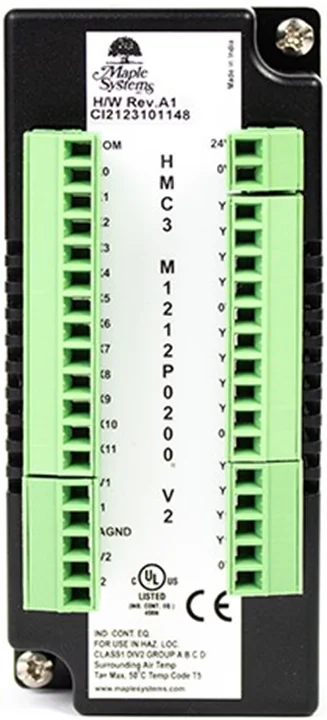
| Specifications | |
| Power | 12 VDC from base |
| Certifications | CE, UL |
| Digital Inputs | 12 bidirectional inputs (2 high-speed pairs) |
| Rated Input Voltage | 24 VDC +/- 15% |
| Rated input current | Up to 5mA (per contact) |
| Input impedance | 4.9K ohms |
| Minimum ON voltage | 15 VDC |
| Maximum OFF voltage | 5 VDC |
| Turn ON Time | 10 mSec |
| Turn OFF Time | 10 mSec |
| Isolation | Optically isolated from internal circuit |
| Analog Inputs | 2 Inputs, each configurable as: 0 to 10V, 0 to 5V; 0 to 20mA, 4-20mA |
| Input Resolution | 16 bit |
| Input Impedance | 3 KΩ |
| Input Accuracy | Overall Accuracy 0.2% of full scale@25°C (max) |
| Digital Outputs | 12 sourcing outputs (PNP-type), 1 PWM |
| Maximum PWM Output Frequency | 1KHz |
| Minimum ON Output Voltage | 22 VDC |
| Maximum ON Output Voltage | 30 VDC |
| Minimum OFF Output Voltage | 0.2 VDC |
| Maximum OFF Output Voltage | 1 VDC |
| Rated Load | 250mA @ 24VDC |
| Nominal load | 96W 6W (resistive) @ 24VDC 6VA (inductive, UPF) |
High-speed Channels | |
| No. of inputs | 2 channel pairs (X0/X1 and X2/X3) |
| Maximum Input Frequency | 200 KHz |
| Maximum Input Count | 4,294,967,295 (32-bit) |
| General | |
| Connection method | Removable terminals (3.81 mm pitch) |
| Operating Temperature | 0 to 55°C |
| Operating Humidity | 10% to 90% (non-condensing) |
| Mechanical Dimension (W x H x D) | 1.88 x 4.25 x 1.61 inches [48x108x41mm] |
Configuration
Use MAPware-7000 to assign input (X and XW), output (Y and YW) and configuration (M and MW) memory addresses to the module. These addresses are created according to the slot location of the module, where nn refers to the slot number (ex. 01…05):
| Function | Register | Access | |
| X0-X11 Digital Inputs | Xnn000-011 (XWnn00) | Read Only | |
| Y0-Y11 Digital Outputs | Ynn000-011 (YWnn00) | Read/Write | |
| High-speed Counter Option | HSC Channel 1 | HSC Channel 2 | |
| HSC Input Pin | X0 | X2 | Read Only |
| Quadrature Inputs | Pair 1 | Pair 2 | |
| Counter Inputs | X0, X1 | X2, X3 | Read Only |
| HSC Configuration Register | MWnn00 | MWnn06 | Read/Write |
| HSC Counter Register (Current Value) | MWnn01 | MWnn07 | Read/Write |
| HSC Preset Register | MWnn03 | MWnn09 | Read/Write |
| HSC Enable Bit | Mnn080 | Mnn176 | Read/Write |
| HSC Reset Bit | Mnn081 | Mnn177 | Read/Write |
| Output Flag | Y2 | Y3 | |
| PWM Outputs | Channel 1 | ||
| Output | Y0 | Read Only | |
| PWM Configuration Register | MWnn24 | Read/Write | |
| Frequency Setting Register | MWnn25 | Read/Write | |
| ON Duty Setting Register (Duty Cycle) | MWnn27 | Read/Write | |
| Pulse Enable Flag | Mnn576 | Read/Write | |
| ON Duty Setting Error Flag | Mnn466 | Read Only | |
| Frequency Setting Error Flag | Mnn467 | Read Only | |
| Analog Inputs | Register | ||
| Input Channel 0 Data | XWnn11 | Read Only | |
| Input Channel 1 Data | XWnn13 | Read Only | |
| Input Channel 0 Config Register | MWnn60 | Read/Write | |
| Input Channel 1 Config Register | MWnn61 | Read/Write | |
Reference the table below when configuring each HSC Configuration Register:
| Input Mode | Output Mode | Register Value |
| Normal Input | N/A | 0 |
| High Speed, Single Phase, Up/Down Counter | Output ON when preset is reached | 2 |
| Output ON when counter is enabled, OFF when preset is reached | 258 | |
| Quadrature 4X | Output ON when preset is reached | 131 |
| Output ON when counter is enabled, OFF when preset is reached | 387 |
Reference the table below when configuring the PWM Configuration Registers:
| Output Mode | Register Value |
| Normal PWM (fixed frequency) | 1 |
| Normal PWM (variable frequency) | 2 |
| CW/CCW (fixed frequency) | 3 |
| CW/CCW (variable frequency) | 4 |
| Pulse/Direction (fixed frequency) | 7 |
| Pulse/Direction (variable frequency) | 8 |
| Trapezoidal (Fixed Pulse Mode) | 9 |
Reference the table below when configuring each Analog Input Configuration Register (MWnn60-MWnn61):
| Input Signal Type | Register Value |
| Voltage, 0 to 10V | 1 |
| Voltage, 0 to 5V | 6 |
| Current, 4 to 20mA | 2 |
| Current, 0 to 20mA | 3 |
The values in the appropriate analog input register range from 0-65535.
| Expansion Module Register Value | Input Values | |||
| 0 to 20mA | 4 to 20mA | 0 to 10V | 0 to 5V | |
| 0 | 0mA | 4mA | 0V | 0V |
| 16384 | 5mA | 8mA | 2.5V | 1.25V |
| 32768 | 10mA | 12mA | 5V | 2.5V |
| 49152 | 15mA | 16mA | 7.5V | 3.75V |
| 65535 | 20mA | 20mA | 10V | 5V |
Wiring
Digital Inputs
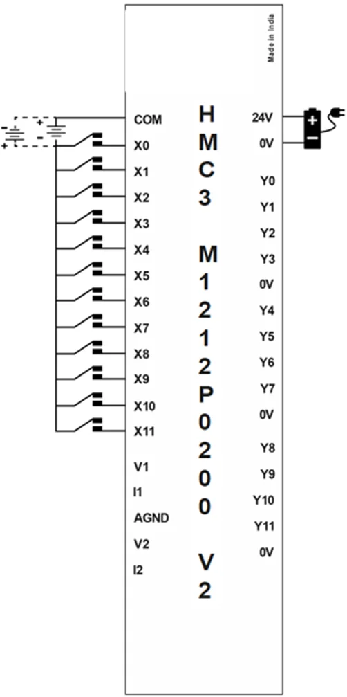
Digital Outputs
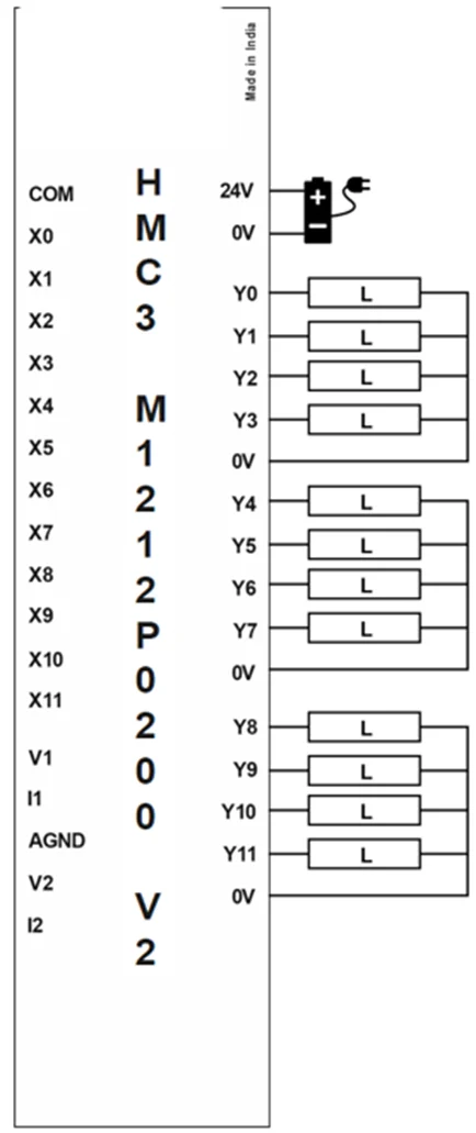
Analog Input (Voltage)
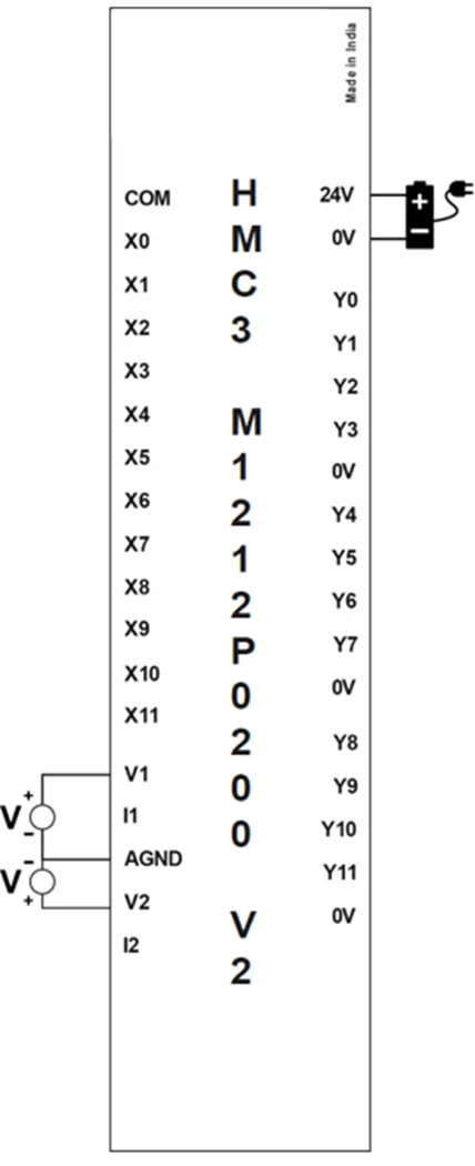
Analog Input (Current)
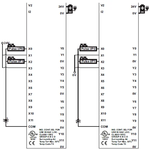
HSC Single Phase Up Counter
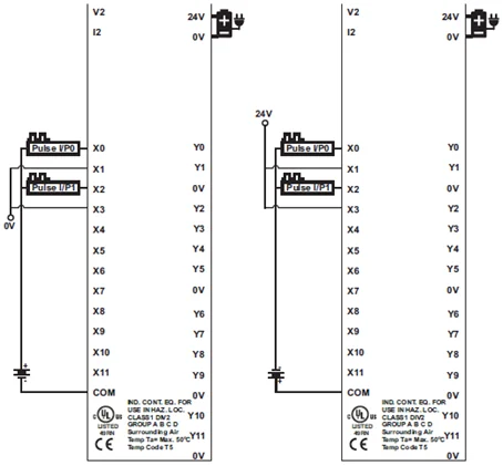
HSC Single Phase Down Counter
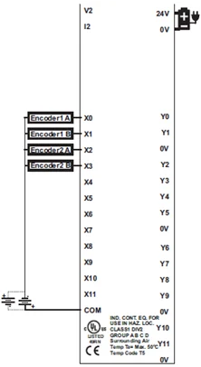
HSC Quadrature
HMC3-M1212Y0200 V2
This module is an input/output module for the HMC2000 and HMC4000 Series models. It has eight digital inputs, two of which are high speed pairs and 12 digital outputs. Two of those digital outputs are sourcing (PNP), and 1 can be configured for PWM, and the other 10 outputs are relay type.
This module also has two analog inputs, each measuring Voltage or Current.
[Note: HMC3 I/O Module V2 Series are only compatible with HMC2000/ HMC4000 Series Base Model]
12 Digital Inputs (2 high-speed pairs up to 200kHz)
12 Digital Outputs (1 PWM up to 1kHz)
2 Analog Inputs
- Voltage: 0-5V, 0-10V
- Current: 0-20mA, 4-20mA
| Specifications | |
| Power | 12 VDC from base |
| Certifications | CE, UL |
| Digital Inputs | 12 bidirectional inputs (2 high-speed pairs) |
| Rated Input Voltage | 24 VDC +/- 15% |
| Rated input current | Up to 5mA (per contact) |
| Input impedance | 4.9K ohms |
| Minimum ON voltage | 15 VDC |
| Maximum OFF voltage | 5 VDC |
| Turn ON Time | 10 mSec |
| Turn OFF Time | 10 mSec |
| Isolation | Optically isolated from internal circuit |
| Analog Inputs | 2 Inputs, each configurable as: 0 to 10V, 0 to 5V; 0 to 20mA, 4-20mA |
| Input Resolution | 16 bit |
| Input Impedance | 3 KΩ |
| Input Accuracy | Overall Accuracy 0.2% of full scale@25°C (max) |
| Digital Outputs | 12 outputs: 10 Relay, 2 Sourcing (PNP-type), 1 PWM |
| Maximum Output Frequency | 1KHz |
| Minimum ON Output Voltage | 22 VDC |
| Maximum ON Output Voltage | 30 VDC |
| Minimum OFF Output Voltage | 0.2 VDC |
| Maximum OFF Output Voltage | 1 VDC |
| Rated Load | 250mA @ 24VDC 2A @230VAC |
| Nominal load | 96W 6W (resistive) @ 24VDC 6VA (inductive, UPF) |
High-speed Channels | |
| No. of inputs | 2 channel pairs (X0/X1 and X2/X3) |
| Maximum Input Frequency | 200 KHz |
| Maximum Input Count | 4,294,967,295 (32-bit) |
| General | |
| Connection method | Removable terminals (3.81 mm pitch) |
| Operating Temperature | 0 to 55°C |
| Operating Humidity | 10% to 90% (non-condensing) |
| Mechanical Dimension (W x H x D) | 1.88 x 4.25 x 1.61 inches [48x108x41mm] |
Configuration
Use MAPware-7000 to assign input (X and XW), output (Y and YW) and configuration (M and MW) memory addresses to the module. These addresses are created according to the slot location of the module, where nn refers to the slot number (ex. 01…05):
| Function | Register | Access | |
| X0-X11 Digital Inputs | Xnn000-011 (XWnn00) | Read Only | |
| Y0-Y11 Digital Outputs | Ynn000-011 (YWnn00) | Read/Write | |
| High-speed Counter Option | HSC Channel 1 | HSC Channel 2 | |
| HSC Input Pin | X0 | X2 | Read Only |
| Quadrature Inputs | Pair 1 | Pair 2 | |
| Counter Inputs | X0, X1 | X2, X3 | Read Only |
| HSC Configuration Register | MWnn00 | MWnn06 | Read/Write |
| HSC Counter Register (Current Value) | MWnn01 | MWnn07 | Read/Write |
| HSC Preset Register | MWnn03 | MWnn09 | Read/Write |
| HSC Enable Bit | Mnn080 | Mnn176 | Read/Write |
| HSC Reset Bit | Mnn081 | Mnn177 | Read/Write |
| Output Flag | Y2 | Y3 | |
| PWM Outputs | Channel 1 | ||
| Output | Y0 | Read Only | |
| PWM Configuration Register | MWnn24 | Read/Write | |
| Frequency Setting Register | MWnn25 | Read/Write | |
| ON Duty Setting Register (Duty Cycle) | MWnn27 | Read/Write | |
| Pulse Enable Flag | Mnn576 | Read/Write | |
| ON Duty Setting Error Flag | Mnn466 | Read Only | |
| Frequency Setting Error Flag | Mnn467 | Read Only | |
| Analog Inputs | Register | ||
| Input Channel 0 Data | XWnn11 | Read Only | |
| Input Channel 1 Data | XWnn13 | Read Only | |
| Input Channel 0 Config Register | MWnn60 | Read/Write | |
| Input Channel 1 Config Register | MWnn61 | Read/Write | |
Reference the table below when configuring each HSC Configuration Register:
| Input Mode | Output Mode | Register Value |
| Normal Input | N/A | 0 |
| High Speed, Single Phase, Up/Down Counter | Output ON when preset is reached | 2 |
| Output ON when counter is enabled, OFF when preset is reached | 258 | |
| Quadrature 4X | Output ON when preset is reached | 131 |
| Output ON when counter is enabled, OFF when preset is reached | 387 |
Reference the table below when configuring the PWM Configuration Registers:
| Output Mode | Register Value |
| Normal PWM (fixed frequency) | 1 |
| Normal PWM (variable frequency) | 2 |
| CW/CCW (fixed frequency) | 3 |
| CW/CCW (variable frequency) | 4 |
| Pulse/Direction (fixed frequency) | 7 |
| Pulse/Direction (variable frequency) | 8 |
| Trapezoidal (Fixed Pulse Mode) | 9 |
Reference the table below when configuring each Analog Input Configuration Register (MWnn60-MWnn61):
| Input Signal Type | Register Value |
| Voltage, 0 to 10V | 1 |
| Voltage, 0 to 5V | 6 |
| Current, 4 to 20mA | 2 |
| Current, 0 to 20mA | 3 |
The values in the appropriate analog input register range from 0-65535.
| Expansion Module Register Value | Input Values | |||
| 0 to 20mA | 4 to 20mA | 0 to 10V | 0 to 5V | |
| 0 | 0mA | 4mA | 0V | 0V |
| 16384 | 5mA | 8mA | 2.5V | 1.25V |
| 32768 | 10mA | 12mA | 5V | 2.5V |
| 49152 | 15mA | 16mA | 7.5V | 3.75V |
| 65535 | 20mA | 20mA | 10V | 5V |
Wiring
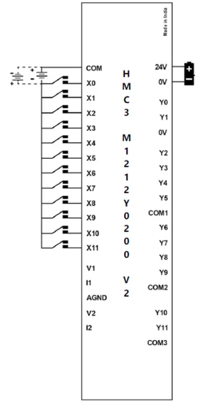
Digital Input
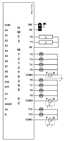
Digital Output
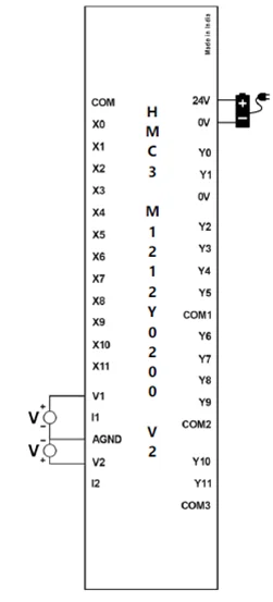
Analog Input (Voltage)
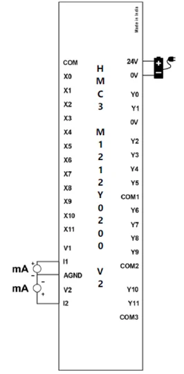
Analog Input (Current)
HSC Single Phase Up Counter
HSC Single Phase Down Counter
HSC Quadrature
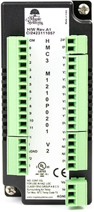
HMC3-M1210P0201 V2
This module is an input/output module for the HMC2000 and HMC4000 Series models. It has twelve digital inputs, two of which are high-speed pairs and 10 sourcing (PNP) digital outputs. One of those digital outputs are PWM.
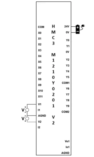
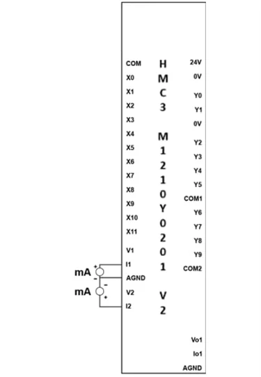
This module also has two analog inputs (Voltage/Current) and one analog output (Voltage/Current).
[Note: HMC3 I/O Module V2 Series are only compatible with HMC2000/ HMC4000 Series Base Model]
12 Digital Inputs (2 high-speed pairs up to 200kHz)
10 Digital Outputs (1 PWM up to 1kHz)
2 Analog Inputs
- Voltage: 0-5V, 0-10V
- Current: 0-20mA, 4-20mA
1 Analog Output
- Voltage: 0-5V, 0-10V
- Current: 0-20mA, 4-20mA
| Specifications | |
| Power | 12 VDC from base |
| Certifications | CE, UL |
| Digital Inputs | 12 bidirectional inputs (2 high-speed pairs) |
| Rated Input Voltage | 24 VDC +/- 15% |
| Rated input current | Up to 5mA (per contact) |
| Input impedance | 4.9K ohms |
| Minimum ON voltage | 15 VDC |
| Maximum OFF voltage | 5 VDC |
| Turn ON Time | 10 msec |
| Turn OFF Time | 10 msec |
| Isolation | Optically isolated from internal circuit |
| Analog Inputs | 2 Inputs, each configurable as: 0 to 10V, 0 to 5V; 0 to 20mA, 4-20mA |
| Input Resolution | 16 bit |
| Input Impedance | 3 KΩ |
| Input Accuracy | Overall Accuracy 0.2% of full scale@25°C (max) |
| Digital Outputs | 10 sourcing outputs (PNP-type), 2 PWM |
| Maximum PWM Output Frequency | 1KHz |
| Minimum ON Output Voltage | 22 VDC |
| Maximum ON Output Voltage | 30 VDC |
| Minimum OFF Output Voltage | 0.2 VDC |
| Maximum OFF Output Voltage | 1 VDC |
| Rated Load | 250mA @ 24VDC |
| Nominal load | 96W 6W (resistive) @ 24VDC 6VA (inductive, UPF) |
| Analog Outputs | 1, configurable as: 0 to 5V, 0 to 10V; 0 to 20mA, 4-20mA |
| Accuracy | Overall Accuracy 0.2% of full scale@25°C (max) |
| Load | 1 KΩ (Min) for V; 500Ω (Max) for mA |
| Output Resolution | 12 bit |
| High-speed Channels | |
| No. of inputs | 2 channel pairs (X0/X1 and X2/X3) |
| Maximum Input Frequency | 200 KHz |
| Maximum Input Count | 4,294,967,295 (32-bit) |
| General | |
| Connection method | Removable terminals (3.81 mm pitch) |
| Operating Temperature | 0 to 55°C |
| Operating Humidity | 10% to 90% (non-condensing) |
| Mechanical Dimension (W x H x D) | 1.88 x 4.25 x 1.61 inches [48x108x41mm] |
Configuration
Use MAPware-7000 to assign input (X and XW), output (Y and YW) and configuration (M and MW) memory addresses to the module. These addresses are created according to the slot location of the module, where nn refers to the slot number (ex. 01…05):
The values in the appropriate analog input register range from 0-65535, while analog output register values range from 0-4095.
| Function | Register | Access | |
| X0-X11 Digital Inputs | Xnn000-011 (XWnn00) | Read Only | |
| Y0-Y9 Digital Outputs | Ynn000-009 (YWnn00) | Read/Write | |
| High-speed Counter Option | HSC Channel 1 | HSC Channel 2 | |
| HSC Input Pin | X0 | X2 | Read Only |
| Quadrature Inputs | Pair 1 | Pair 2 | |
| Counter Inputs | X0, X1 | X2, X3 | Read Only |
| HSC Configuration Register | MWnn00 | MWnn06 | Read/Write |
| HSC Counter Register (Current Value) | MWnn01 | MWnn07 | Read/Write |
| HSC Preset Register | MWnn03 | MWnn09 | Read/Write |
| HSC Enable Bit | Mnn080 | Mnn176 | Read/Write |
| HSC Reset Bit | Mnn081 | Mnn177 | Read/Write |
| Output Flag | Y2 | Y3 | |
| PWM Outputs | Channel 1 | Channel 2 | |
| Output | Y0 | Y1 | Read Only |
| PWM Configuration Register | MWnn24 | MWnn30 | Read/Write |
| Frequency Setting Register | MWnn25 | MWnn31 | Read/Write |
| ON Duty Setting Register (Duty Cycle) | MWnn27 | MWnn33 | Read/Write |
| Pulse Enable Flag | Mnn576 | Mnn577 | Read/Write |
| ON Duty Setting Error Flag | Mnn466 | Mnn471 | Read Only |
| Frequency Setting Error Flag | Mnn467 | Mnn472 | Read Only |
| Analog Inputs | Register | ||
| Input Channel 0 Data | XWnn11 | Read Only | |
| Input Channel 1 Data | XWnn13 | Read Only | |
| Input Channel 0 Config Register | MWnn60 | Read/Write | |
| Input Channel 1 Config Register | MWnn61 | Read/Write | |
| Analog Outputs | Register | ||
| Output Channel 0 Data (Voltage) | YWnn01 | Read/Write | |
| Output Channel 0 Data (Current) | YWnn02 | Read/Write | |
| Output Channel 0 Config Register | MWnn68 | Read/Write | |
Reference the table below when configuring each HSC Configuration Register:
| Input Mode | Output Mode | Register Value |
| Normal Input | N/A | 0 |
| High Speed, Single Phase, Up/Down Counter | Output ON when preset is reached | 2 |
| Output ON when counter is enabled, OFF when preset is reached | 258 | |
| Quadrature 4X | Output ON when preset is reached | 131 |
| Output ON when counter is enabled, OFF when preset is reached | 387 |
Reference the table below when configuring the PWM Configuration Registers:
| Output Mode | Register Value |
| Normal PWM (fixed frequency) | 1 |
| Normal PWM (variable frequency) | 2 |
| CW/CCW (fixed frequency) | 3 |
| CW/CCW (variable frequency) | 4 |
| Pulse/Direction (fixed frequency) | 7 |
| Pulse/Direction (variable frequency) | 8 |
| Trapezoidal (Fixed Pulse Mode) | 9 |
Reference the tables below when configuring each Analog Input and Output Configuration Register:
| Input Signal Type | Register Value |
| Voltage, 0 to 10V | 1 |
| Voltage, 0 to 5V | 6 |
| Current, 4 to 20mA | 2 |
| Current, 0 to 20mA | 3 |
| Output Signal Type | Register Value |
| Voltage, 0 to 10V | 2 |
| Voltage, 0 to 5V | 1 |
| Current, 4 to 20mA | 5 |
| Current, 0 to 20mA | 6 |
| Expansion Module Register Value | Input Values | |||
| 0 to 20mA | 4 to 20mA | 0 to 10V | 0 to 5V | |
| 0 | 0mA | 4mA | 0V | 0V |
| 16384 | 5mA | 8mA | 2.5V | 1.25V |
| 32768 | 10mA | 12mA | 5V | 2.5V |
| 49152 | 15mA | 16mA | 7.5V | 3.75V |
| 65535 | 20mA | 20mA | 10V | 5V |
| Expansion Module Register Value | Output Values | |
| 0 to 10V | 4 to 20mA | |
| 0 | 0 | 4mA |
| 1024 | 2.5V | 8mA |
| 2048 | 5V | 12mA |
| 3072 | 7.5V | 16mA |
| 4095 | 10V | 20mA |
Wiring
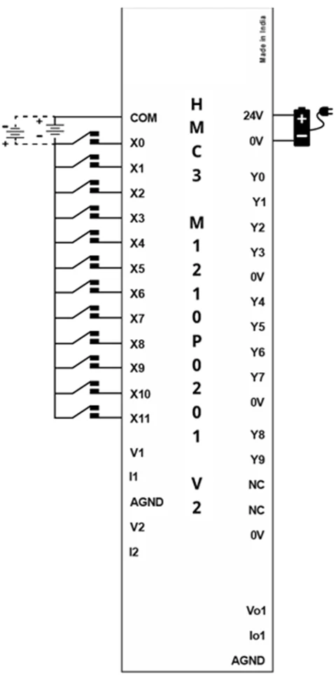
Digital Inputs
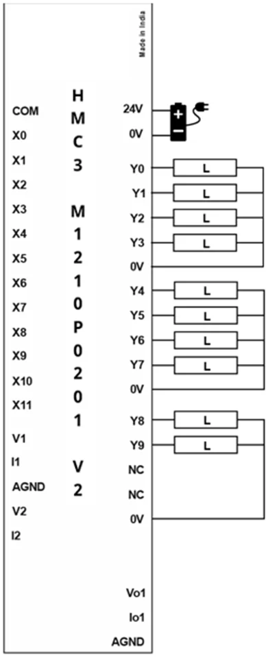
Digital Outputs
Analog Input (Voltage)

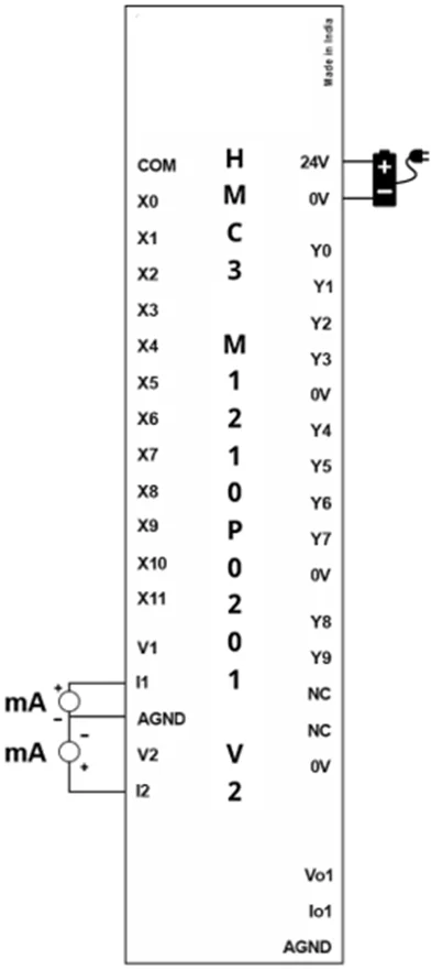
Analog Input (Current)
Analog Output (Voltage)
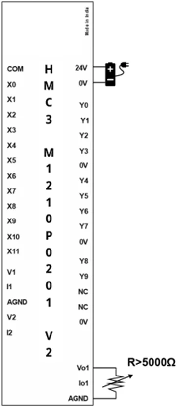
Analog Output (Current)
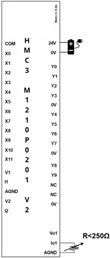
HSC Single Phase Up Counter
HSC Single Phase Down Counter
HSC Quadrature
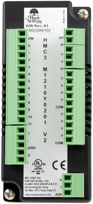
HMC3-M1210Y0201 V2
This module is an input/output module for the HMC2000 and HMC4000 Series models. It has twelve digital inputs, two of which are high-speed pairs and 10 sourcing (PNP) digital outputs. One of those digital outputs are PWM.
This module also has two analog inputs (Voltage/Current) and one analog output (Voltage/Current).
[Note: HMC3 I/O Module V2 Series are only compatible with HMC2000/ HMC4000 Series Base Model]
12 Digital Inputs (2 high-speed pairs up to 200kHz)
10 Digital Outputs (8 Relay, 2 PNP w/ 1 PWM up to 1kHz)
2 Analog Inputs
- Voltage: 0-5V, 0-10V
- Current: 0-20mA, 4-20mA
1 Analog Output
- Voltage: 0-5V, 0-10V
- Current: 0-20mA, 4-20mA
| Specifications | |
| Power | 12 VDC from base |
| Certifications | CE, UL |
| Digital Inputs | 12 bidirectional inputs (2 high-speed pairs) |
| Rated Input Voltage | 24 VDC +/- 15% |
| Rated input current | Up to 5mA (per contact) |
| Input impedance | 4.9K ohms |
| Minimum ON voltage | 15 VDC |
| Maximum OFF voltage | 5 VDC |
| Turn ON Time | 10 msec |
| Turn OFF Time | 10 msec |
| Isolation | Optically isolated from internal circuit |
| Analog Inputs | 2 Inputs, each configurable as: 0 to 10V, 0 to 5V; 0 to 20mA, 4-20mA |
| Input Resolution | 16 bit |
| Input Impedance | 3 KΩ |
| Input Accuracy | Overall Accuracy 0.2% of full scale@25°C (max) |
| Digital Outputs | 10 outputs: 8 Relay, 2 Sourcing (PNP-type) |
| Maximum PWM Output Frequency | 1KHz |
| Minimum ON Output Voltage | 22 VDC |
| Maximum ON Output Voltage | 30 VDC |
| Minimum OFF Output Voltage | 0.2 VDC |
| Maximum OFF Output Voltage | 1 VDC |
| Rated Load | 250mA @ 24VDC 2A @230VAC |
| Nominal load | 96 Ohms 6W (resistive) @ 24VDC 6VA (inductive, UPF) |
| Analog Outputs | 1, configurable as: 0 to 5V, 0 to 10V; 0 to 20mA, 4-20mA |
| Accuracy | Overall Accuracy 0.2% of full scale@25°C (max) |
| Load | 1 KΩ (Min) for V; 500Ω (Max) for mA |
| Output Resolution | 12 bit |
| High-speed Channels | |
| No. of inputs | 2 channel pairs (X0/X1 and X2/X3) |
| Maximum Input Frequency | 200 KHz |
| Maximum Input Count | 4,294,967,295 (32-bit) |
| General | |
| Connection method | Removable terminals (3.81 mm pitch) |
| Operating Temperature | 0 to 55°C |
| Operating Humidity | 10% to 90% (non-condensing) |
| Mechanical Dimension (W x H x D) | 1.88 x 4.25 x 1.61 inches [48x108x41mm] |
Configuration
Use MAPware-7000 to assign input (X and XW), output (Y and YW) and configuration (M and MW) memory addresses to the module. These addresses are created according to the slot location of the module, where nn refers to the slot number (ex. 01…05):
| Function | Register | Access | |
| X0-X11 Digital Inputs | Xnn000-011 (XWnn00) | Read Only | |
| Y0-Y9 Digital Outputs | Ynn000-009 (YWnn00) | Read/Write | |
| High-speed Counter Option | HSC Channel 1 | HSC Channel 2 | |
| HSC Input Pin | X0 | X2 | Read Only |
| Quadrature Inputs | Pair 1 | Pair 2 | |
| Counter Inputs | X0, X1 | X2, X3 | Read Only |
| HSC Configuration Register | MWnn00 | MWnn06 | Read/Write |
| HSC Counter Register (Current Value) | MWnn01 | MWnn07 | Read/Write |
| HSC Preset Register | MWnn03 | MWnn09 | Read/Write |
| HSC Enable Bit | Mnn080 | Mnn176 | Read/Write |
| HSC Reset Bit | Mnn081 | Mnn177 | Read/Write |
| Output Flag | Y2 | Y3 | |
| PWM Outputs | Channel 1 | Channel 2 | |
| Output | Y0 | Read Only | |
| PWM Configuration Register | MWnn24 | Read/Write | |
| Frequency Setting Register | MWnn25 | Read/Write | |
| ON Duty Setting Register (Duty Cycle) | MWnn27 | Read/Write | |
| Pulse Enable Flag | Mnn576 | Read/Write | |
| ON Duty Setting Error Flag | Mnn466 | Read Only | |
| Frequency Setting Error Flag | Mnn467 | Read Only | |
| Analog Inputs | Register | ||
| Input Channel 0 Data | XWnn11 | Read Only | |
| Input Channel 1 Data | XWnn13 | Read Only | |
| Input Channel 0 Config Register | MWnn60 | Read/Write | |
| Input Channel 1 Config Register | MWnn61 | Read/Write | |
| Analog Outputs | Register | ||
| Output Channel 0 Data (Voltage) | YWnn01 | Read/Write | |
| Output Channel 0 Data (Current) | YWnn02 | Read/Write | |
| Output Channel 0 Config Register | MWnn68 | Read/Write | |
Reference the table below when configuring each HSC Configuration Register:
| Input Mode | Output Mode | Register Value |
| Normal Input | N/A | 0 |
| High Speed, Single Phase, Up/Down Counter | Output ON when preset is reached | 2 |
| Output ON when counter is enabled, OFF when preset is reached | 258 | |
| Quadrature 4X | Output ON when preset is reached | 131 |
| Output ON when counter is enabled, OFF when preset is reached | 387 |
Reference the table below when configuring the PWM Configuration Registers:
| Output Mode | Register Value |
| Normal PWM (fixed frequency) | 1 |
| Normal PWM (variable frequency) | 2 |
| CW/CCW (fixed frequency) | 3 |
| CW/CCW (variable frequency) | 4 |
| Pulse/Direction (fixed frequency) | 7 |
| Pulse/Direction (variable frequency) | 8 |
| Trapezoidal (Fixed Pulse Mode) | 9 |
Reference the tables below when configuring each Analog Input and Output Configuration Register:
| Input Signal Type | Register Value |
| Voltage, 0 to 10V | 1 |
| Voltage, 0 to 5V | 6 |
| Current, 4 to 20mA | 2 |
| Current, 0 to 20mA | 3 |
| Output Signal Type | Register Value |
| Voltage, 0 to 10V | 2 |
| Voltage, 0 to 5V | 1 |
| Current, 4 to 20mA | 5 |
| Current, 0 to 20mA | 6 |
The values in the appropriate analog input register range from 0-65535, while analog output register values range from 0-4095.
| Expansion Module Register Value | Input Values | |||
| 0 to 20mA | 4 to 20mA | 0 to 10V | 0 to 5V | |
| 0 | 0mA | 4mA | 0V | 0V |
| 16384 | 5mA | 8mA | 2.5V | 1.25V |
| 32768 | 10mA | 12mA | 5V | 2.5V |
| 49152 | 15mA | 16mA | 7.5V | 3.75V |
| 65535 | 20mA | 20mA | 10V | 5V |
| Expansion Module Register Value | Output Values | |
| 0 to 10V | 4 to 20mA | |
| 0 | 0 | 4mA |
| 1024 | 2.5V | 8mA |
| 2048 | 5V | 12mA |
| 3072 | 7.5V | 16mA |
| 4095 | 10V | 20mA |
Wiring
Digital Inputs
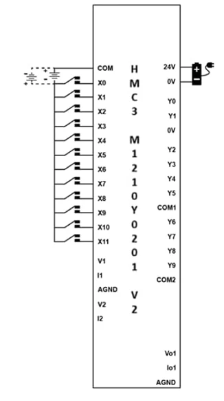
Digital Outputs

Analog Input (Voltage)
Analog Input (Current)
Analog Output (Voltage)

Analog Output (Current)
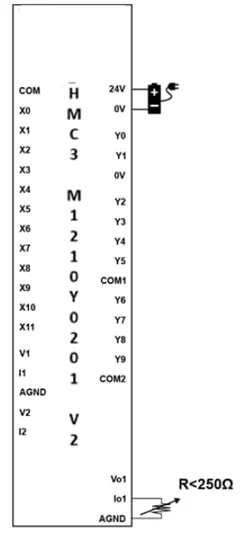
HSC Single Phase Up Counter
HSC Single Phase Down Counter
HSC Quadrature
HMC3-M1614Y V2
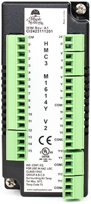
This module is a digital input/output module for the HMC2000 and HMC4000 Series models.
It has 16 digital inputs. The module also features 14 digital outputs, 2 sourcing (PNP) outputs with 1 capable of PWM operation and 12 relay type outputs.
[Note: HMC3 I/O Module V2 Series are only compatible with HMC2000/ HMC4000 Series Base Model]
16 Digital Inputs (2 high-speed pairs up to 200kHz)
14 Digital Outputs (12 Relay, 2 PNP w/ 1 PWM up to 1kHz)
| Specifications | |
| Power | 3.3 VDC from HMC3000 base |
| Certifications | CE, UL |
| Digital Inputs | 16 bidirectional inputs (2 high-speed pairs) |
| Rated Input Voltage | 24 VDC +/- 15% |
| Rated input current | Up to 5mA (per contact) |
| Input impedance | 4.9K ohms |
| Minimum ON voltage | 15 VDC |
| Maximum OFF voltage | 5 VDC |
| Turn ON Time | 10 mSec |
| Turn OFF Time | 10 mSec |
| Isolation | Optically isolated from internal circuit |
| Digital Outputs | 14 outputs: 12 Relay, 2 Sourcing (PNP-type) / 1 PWM |
| Maximum PWM Output Frequency | 1KHz |
| Minimum ON Output Voltage | 22 VDC |
| Maximum ON Output Voltage | 30 VDC |
| Minimum OFF Output Voltage | 0.2 VDC |
| Maximum OFF Output Voltage | 1 VDC |
| Rated Load | 250mA @ 24VDC 2A @230VAC |
| Nominal load | 96W 6W (resistive) @ 24VDC 6VA (inductive, UPF) |
| High-speed Channels | |
| No. of inputs | 2 channel pairs (X0/X1 and X2/X3) |
| Maximum Input Frequency | 200 KHz |
| Maximum Input Count | 4,294,967,295 (32-bit) |
| General | |
| Connection method | Removable terminals (3.81 mm pitch) |
| Operating Temperature | 0 to 55°C |
| Operating Humidity | 10% to 90% (non-condensing) |
| Mechanical Dimension (W x H x D) | 1.88 x 4.25 x 1.61 inches [48x108x41mm] |
| Function | Register | Access |
| X0-X15 Digital Inputs | Xnn000-015 (XWnn00) | Read Only |
| Y0-Y13 Digital Outputs | Ynn000-013 (YWnn00) | Read/Write |
Configuration
Use MAPware-7000 to assign input (X and XW), output (Y and YW) and configuration (M and MW) memory addresses to the module. These addresses are created according to the slot location of the module, where nn refers to the slot number (ex. 01…05):
| Function | Register | Access | |
| X0-X15 Digital Inputs | Xnn000-015 (XWnn00) | Read Only | |
| Y0-Y13 Digital Outputs | Ynn000-013 (YWnn00) | Read/Write | |
| High-speed Counter Option | HSC Channel 1 | HSC Channel 2 | |
| HSC Input Pin | X0 | X2 | Read Only |
| Quadrature Inputs | Pair 1 | Pair 2 | |
| Counter Inputs | X0, X1 | X2, X3 | Read Only |
| HSC Configuration Register | MWnn00 | MWnn06 | Read/Write |
| HSC Counter Register (Current Value) | MWnn01 | MWnn07 | Read/Write |
| HSC Preset Register | MWnn03 | MWnn09 | Read/Write |
| HSC Enable Bit | Mnn080 | Mnn176 | Read/Write |
| HSC Reset Bit | Mnn081 | Mnn177 | Read/Write |
| Output Flag | Y2 | Y3 | |
| PWM Outputs | Channel 1 | ||
| Output | Y0 | Read Only | |
| PWM Configuration Register | MWnn24 | Read/Write | |
| Frequency Setting Register | MWnn25 | Read/Write | |
| ON Duty Setting Register (Duty Cycle) | MWnn27 | Read/Write | |
| Pulse Enable Flag | Mnn576 | Read/Write | |
| ON Duty Setting Error Flag | Mnn466 | Read Only | |
| Frequency Setting Error Flag | Mnn467 | Read Only | |
Reference the table below when configuring each HSC Configuration Register:
| Input Mode | Output Mode | Register Value |
| Normal Input | N/A | 0 |
| High Speed, Single Phase, Up/Down Counter | Output ON when preset is reached | 2 |
| Output ON when counter is enabled, OFF when preset is reached | 258 | |
| Quadrature 4X | Output ON when preset is reached | 131 |
| Output ON when counter is enabled, OFF when preset is reached | 387 |
Reference the table below when configuring the PWM Configuration Registers:
| Output Mode | Register Value |
| Normal PWM (fixed frequency) | 1 |
| Normal PWM (variable frequency) | 2 |
| CW/CCW (fixed frequency) | 3 |
| CW/CCW (variable frequency) | 4 |
| Pulse/Direction (fixed frequency) | 7 |
| Pulse/Direction (variable frequency) | 8 |
| Trapezoidal (Fixed Pulse Mode) | 9 |
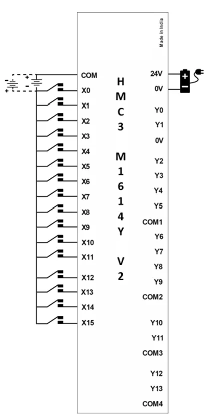
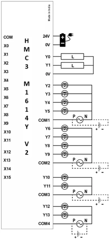
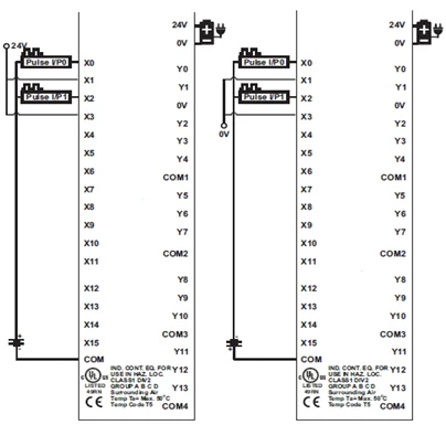
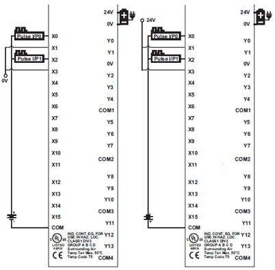
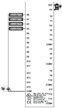
Wiring
Digital Inputs
Digital Outputs
HSC Single Phase Up Counter
HSC Single Phase Down Counter
HSC Quadrature
HMC3-M1616P V2
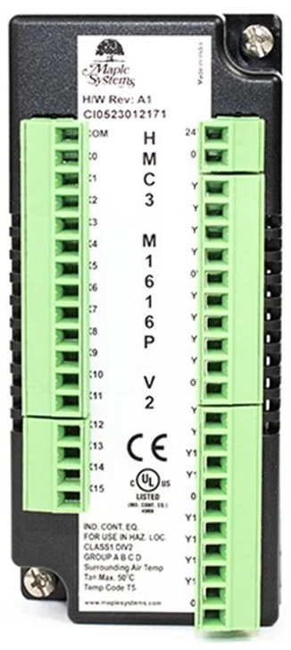
This module is a digital input/output module for the HMC2000 and HMC4000 Series models. It has 16 digital inputs.
The module also features 16 digital sourcing (PNP) outputs, 1 of which can be used for PWM operation.
[Note: HMC3 I/O Module V2 Series are only compatible with HMC2000/ HMC4000 Series Base Model]
16 Digital Inputs (2 high-speed pairs up to 200kHz)
16 Digital Outputs (1 PWM up to 1kHz)
| Specifications | |
| Power | 12 VDC from base |
| Certifications | CE, UL |
| Digital Inputs | 16 bidirectional inputs (2 high-speed pairs) |
| Rated Input Voltage | 24 VDC +/- 15% |
| Rated input current | Up to 5mA (per contact) |
| Input impedance | 4.9K ohms |
| Minimum ON voltage | 15 VDC |
| Maximum OFF voltage | 5 VDC |
| Turn ON Time | 10 mSec |
| Turn OFF Time | 10 mSec |
| Isolation | Optically isolated from internal circuit |
| Digital Outputs | 16 sourcing outputs (PNP-type), 1 PWM |
| Maximum PWM Output Frequency | 1KHz |
| Minimum ON Output Voltage | 22 VDC |
| Maximum ON Output Voltage | 30 VDC |
| Minimum OFF Output Voltage | 0.2 VDC |
| Maximum OFF Output Voltage | 1 VDC |
| Rated Load | 250mA @ 24VDC |
| Nominal load | 96 Ohms 6W (resistive) @ 24VDC 6VA (inductive, UPF) |
| High-speed Channels | |
| No. of inputs | 2 channel pairs (X0/X1 and X2/X3) |
| Maximum Input Frequency | 200 KHz |
| Maximum Input Count | 4,294,967,295 (32-bit) |
| General | |
| Connection method | Removable terminals (3.81 mm pitch) |
| Operating Temperature | 0 to 55°C |
| Operating Humidity | 10% to 90% (non-condensing) |
| Mechanical Dimension (W x H x D) | 1.88 x 4.25 x 1.61 inches [48x108x41mm] |
Configuration
Use MAPware-7000 to assign input (X and XW), output (Y and YW) and configuration (M and MW) memory addresses to the module. These addresses are created according to the slot location of the module, where nn refers to the slot number (ex. 01…05):
| Function | Register | Access | |
| X0-X15 Digital Inputs | Xnn000-015 (XWnn00) | Read Only | |
| Y0-Y15 Digital Outputs | Ynn000-015 (YWnn00) | Read/Write | |
| High-speed Counter Option | HSC Channel 1 | HSC Channel 2 | |
| HSC Input Pin | X0 | X2 | Read Only |
| Quadrature Inputs | Pair 1 | Pair 2 | |
| Counter Inputs | X0, X1 | X2, X3 | Read Only |
| HSC Configuration Register | MWnn00 | MWnn06 | Read/Write |
| HSC Counter Register (Current Value) | MWnn01 | MWnn07 | Read/Write |
| HSC Preset Register | MWnn03 | MWnn09 | Read/Write |
| HSC Enable Bit | Mnn080 | Mnn176 | Read/Write |
| HSC Reset Bit | Mnn081 | Mnn177 | Read/Write |
| Output Flag | Y2 | Y3 | |
| PWM Outputs | Channel 1 | ||
| Output | Y0 | Read Only | |
| PWM Configuration Register | MWnn24 | Read/Write | |
| Frequency Setting Register | MWnn25 | Read/Write | |
| ON Duty Setting Register (Duty Cycle) | MWnn27 | Read/Write | |
| Pulse Enable Flag | Mnn576 | Read/Write | |
| ON Duty Setting Error Flag | Mnn466 | Read Only | |
| Frequency Setting Error Flag | Mnn467 | Read Only | |
Reference the table below when configuring each HSC Configuration Register:
| Input Mode | Output Mode | Register Value |
| Normal Input | N/A | 0 |
| High Speed, Single Phase, Up/Down Counter | Output ON when preset is reached | 2 |
| Output ON when counter is enabled, OFF when preset is reached | 258 | |
| Quadrature 4X | Output ON when preset is reached | 131 |
| Output ON when counter is enabled, OFF when preset is reached | 387 |
Reference the table below when configuring the PWM Configuration Registers:
| Output Mode | Register Value |
| Normal PWM (fixed frequency) | 1 |
| Normal PWM (variable frequency) | 2 |
| CW/CCW (fixed frequency) | 3 |
| CW/CCW (variable frequency) | 4 |
| Pulse/Direction (fixed frequency) | 7 |
| Pulse/Direction (variable frequency) | 8 |
| Trapezoidal (Fixed Pulse Mode) | 9 |
Wiring
Digital Inputs
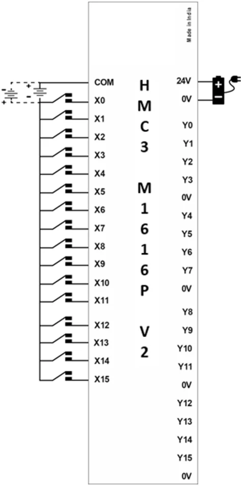
Digital Outputs
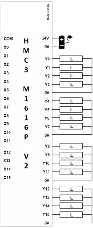
HSC Single Phase Up Counter
HSC Single Phase Down Counter
HSC Quadrature