Data Logger and Trending
The Data Logger is used to record the values of tags over time. The collected data is stored in non-volatile memory inside the HMC or, for models with a SD card slot, can be saved directly to an SD card. This data can be displayed in graphic format on the HMC using the Historical Trend Object. You can also upload the collected data to a computer (using MAPware) or to an attached USB Flash drive as a CSV file. The HMC2000 series allows data to be sent from the SD card directly to a file transfer protocol (ftp) server. On the HMC4000, data log files can be accessed directly from the unit via a self-hosted FTP server on an attached SD card/USB drive. The Data Logging feature is most often used for data acquisition. The HMC gathers and saves valuable information about the industrial system it is connected to. This information can then be reviewed at any time to increase knowledge of what is happening in the system. Real time data can be monitored with the Real Time Trend and XY Plot objects.
Factors to Consider
Before you begin configuring the Data Logger function, you need to determine the following:
How much internal HMC memory will you need? During data logger setup, you can select the amount of reserved memory to be allocated for the data you are collecting. To compute the amount of memory required, consider:
- Data Type used (i.e. 2 byte Integer or 4 byte Integer/Float)
- Number of Tags that you will be recording
- How often you will be recording (time interval)
- Total length of time that you wish to capture
For example, I want to capture data from five registers in my PLC. I want to read these registers every 5 seconds over a period of one 24 hour period. The registers are 16 bit data type.
Therefore, my calculations for memory requirements are:
2 (bytes per 16 bit register)* 5 (no of registers) = 10 bytes + 8 bytes overhead for capturing the date and time of each data read. Total is 18 bytes.
I will be reading 12 times per minute which means 720 times per hour which means 17280 times per 24 hour period.
Therefore, I will need 18 (bytes per reading) * 17280 = 311040 bytes or 311KB.
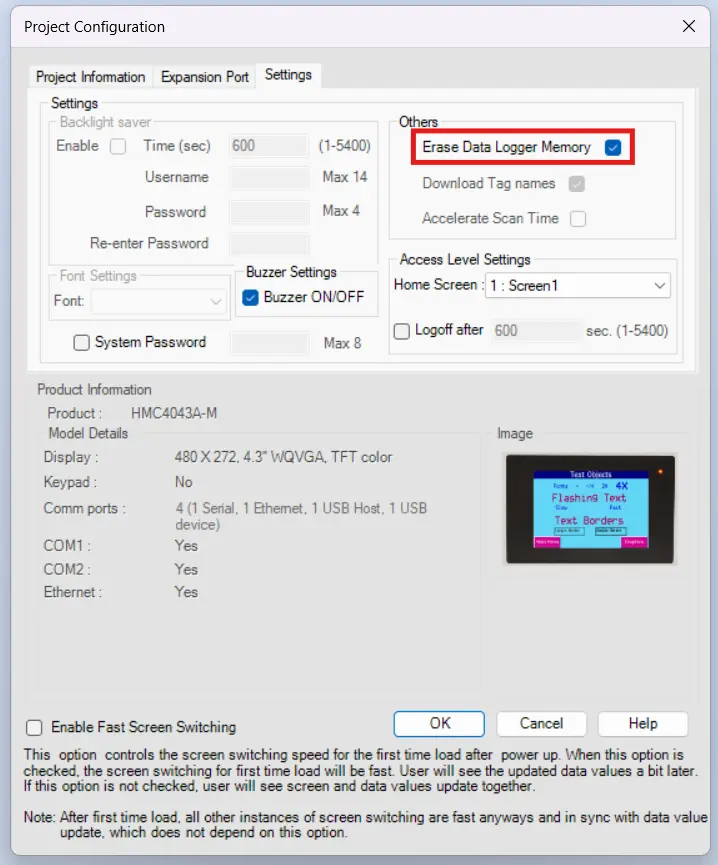
Do you want the option to erase the Data Logger Memory during project download? If so, check the ‘Erase Data Logger Memory’ option located in the Settings tab of the Project Configuration dialog box. This dialog appears whenever you start a new project, or click Project > Properties:
Determine which HMC or PLC data registers you wish to monitor and add these to the tag database.
Determine how you wish to capture the data (Logging Mode):
- Power up – continuously captures data at a predefined frequency while power is applied to HMC.
- Start/Stop Time – captures data at a predefined time period and frequency during each 24 hour cycle.
- Key Task – captures data at a predefined frequency but the time period is determined by manually starting/stopping the data collection via the membrane function keys or the Advanced Bit Button.
- Logging with Run Time Frequency – similar to the Power Up option above except that the frequency of capturing data is determined by the current value in a 16 bit internal memory register. This feature allows you to vary the capture frequency during operation.
- Bit Task – similar to the Key Task option but the data collection begins when an internal predefined bit (S00028-S00031) is set and continues at the predefined frequency until the bit is reset. This provides the ability to vary the start/stop times using ladder instructions in a logic block.
- Event Based – Data is captured each time an assigned bit is triggered.
Internal Data Logger
Click the Data Logger folder in the Project Information directory, or click Define > Data Logger from the standard menu. The HMC2000 series has an option for logging data to Internal memory or External memory while the HMC4000 series has moved that option into the data logger configuration.
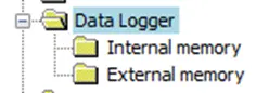
The external memory option allows the logger to write directly to an SD card inserted in the SD card slot. The external memory option also allows the HMC to act as an ftp client and send from the data log to an ftp server.
Internal Memory Logging Configuration
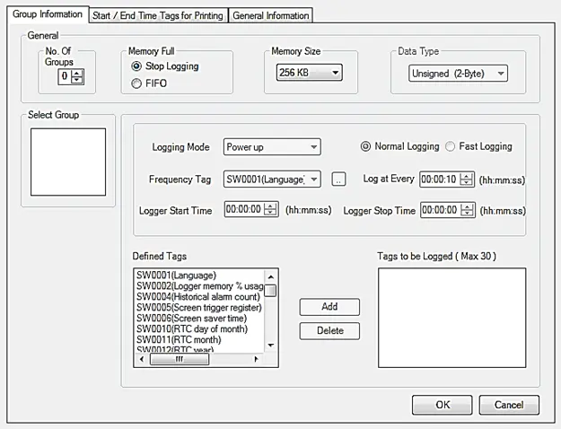
Select the Internal memory option to display the Data Logger configuration window:
Configuration Settings
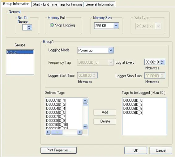
Click the Group Information tab:
- No. of Groups: Data Logging is configured according to “groups”. A “group” is a collection of registers that the HMC will poll and record data according to the “logging mode” selected. Each group can have a maximum of 30 registers. Up to four groups can be created. Use this box to enter how many data groups you need.
- Memory Full: options are Stop Logging or FIFO.
- Stop Logging: the HMC will stop logging data once the memory reserved has been used. You must clear the memory by using the Clear Memory option in the Key Specific Task for function keys or the Advanced Bit button. Or you can clear the memory by enabling the ‘Erase Data Logger Memory’ option under the Settings tab in the Project Configuration dialog box (see Project > Properties) and downloading a project into the HMC.
- FIFO: Once the data logger is full, the oldest data sample will be overwritten, and new data will continue to be logged.
- Memory Size: options available depend on the model being used. This is the amount of memory allocated for all of the groups combined. Select the most appropriate setting for your needs but remember that any memory allocated to the data logger reduces the amount of memory available for the rest of your project (click Tools > Application Memory Status for a breakdown of memory usage).
- the HMC4000s also have an option to limit data sampling by the number of samples in each group.
- Data Type: only selectable once a data logging group is selected. Options are 2 Byte (Signed or Unsigned), 4 Byte (Signed or Unsigned ), and 4 Byte (Float). This option applies to all tags in a given group and determines how the data logger will interpret the data collected. Only tags that are configured with the appropriate byte length (i.e. 2 bytes {1 word} for Data Type: 2 Byte {Int}, and 4 bytes {2 words} for Data Type: 4 Byte {Int or Float}) in the tag database will show in the Defined Tags box.
- In an HMC4000 project, instead of “Data Type” you’ll have a “CSV Export” option.
- You can either export your Data Logger as a single CSV or as multiple different CSV files.
- Select Group: Once you have selected how many data groups you need in the No. of Groups box, the data groups will be listed (ex. Group1, Group2, etc.). Click each Group to edit that group’s attributes.
- Logging mode: this setting determines how and when the HMC collects data. Each group can have a different logging mode. There are six options for the logging mode:
- Power up – collects data immediately after the HMC has initialized, according to the time value entered into ‘Log at Every’ field. Therefore, if the value entered into this field is 00:00:10, then the HMC records the data every ten seconds after initial power-up.
- Start/Stop Time – this option is used if you wish to collect data during a specific time period every day. The starting time is entered in the Logger Start Time field and end time in the Logger Stop Time field. Between these time periods, the HMC collects data continuously according to the frequency specified in the Log at Every field.
- Key Task – the Start and Stop time are controlled by membrane function keys, the Multi-Task Single-State button, or the Multi-Task Multi-State button (using the Key Specific Task option). The frequency of data collection is specified using the Log at Every field.
- Logging with Run Time Frequency – the frequency of capturing data is determined by the current value in a 16 bit memory register (can be internal or a PLC register). This feature allows you to vary the capture frequency during operation. The HMC interprets the value in the Frequency Tag as minutes (this value must be > 30 minutes).
- Note: This mode is only available for Group1.
- Frequency Tag (Logging with Run Time Frequency mode): This is the tag register (internal or PLC) used to determine how often to capture the data.
- Bit Task – the Start and Stop time is controlled by one of four predefined system bits (S0028-S0031) located in the tag database. The frequency of data collection is specified using the Log at Every field.
- on an HMC4000, you can choose a tag to start the data sampling
- Event Based – data logging is controlled using a ‘logging bit’ which is any HMC internal memory bit (external PLC bits not allowed) configured in the task database. The data is captured based upon the logging bit changing state according to one of the following three options: Positive Edge (transition from 0 to 1), Negative Edge (transition from 1 to 0), and Both Edges.
- Logging Bit (Event Based mode): this is the tag bit (internal only) that determines when data is captured.
- Logging Event (Event Based mode): this is the ‘event’ that triggers the Data Logger to capture data. Options are Positive Edge (capture when bit transitions from Off to On), Negative Edge (when bit transitions from On to Off), and Both.
- Logging Speed (Event Based mode):
- Normal logging: Data will be displayed as HH:MM:SS is generated .CSV files
- Fast logging: Data will be displayed as HH:MM:SS:mS in generated .CSV files
- Log at Every: this is the time interval or frequency of data capture used by Power Up, Start/Stop Time, Key Task, and Bit Task modes.
- Logger Start Time (Start/Stop mode): this is the set time at which the Data Logger starts capturing data (frequency based upon the Log at Every setting).
- Logger Stop Time (Start/Stop mode): same as Start Time above, except this is when the Data Logger stops capturing the data.
- Defined Tags: this list displays all of the tags available in the tag database which are the same size (ex 2 Byte Signed or Unsigned) as the Data Type selected in the General section. Scroll through the tags until you find the one you wish to use. Click the tag to highlight it, and then click the Add button to move the selected tag over to the Tags to be Logged list.
- On an HMC4000 project:
- You’ll have additional option to set a file name for the CSV export
- You can also set the maximum number of samples the group will take if you have “sample number” selected above as the data sampling limiter
- Tags to be logged: this is the list of tags that the selected data group uses to capture and record data. A maximum of 30 tags is allowed per group.
Note: to remove a tag from this list, simply click the tag to highlight it, and then click the Delete button. The highlighted tag is removed from this list and placed back into the Defined Tags list.
Note: deleting a tag from this list does not delete the tag from the tag database.
Printing Internal Memory Data Logs (HMC2000 only)
In addition to capturing and storing data into memory, the HMC2000s can also send internal memory Data Logger records to a connected serial printer. To print you must:
- Connect a serial printer to COM1 or COM2 of the HMC
- Configure the serial printer protocol driver in the Network Configuration folder.
- Create a Data Log group in internal memory using the Data Logger folder.
- Click the Print Properties button in the Data Logger to configure what is to be printed (see Formatting Data Logger Printouts)
- Click the Start/End Time Tags for Printing tab in the Data Logger. This tab is used to configure what section of the captured Data Log memory (based upon the Start and Stop Times) is to be sent to the serial printer (see Configuring Print Time for the Data Logger below).
- Create a Function Key (or Multi-Task Single-State Button) with the Key’s Specific Task: Start Printing of Group # Port #. This key initiates the printing sequence.
- Create a Function Key (or Multi-Task Single-State Button) with the Key’s Specific Task: Stop Printing of Group # Port #. This key ends the printing sequence.
Formatting Data Logger Printouts
You can define the data that you wish to be sent to a serial printer and even configure how you want this data to be formatted. This is done by clicking the Print Properties button in the Group Information tab of the Data Logger.
Note: To display the Print Properties button you must:
- Highlight a group in the Groups box
- Make sure that the highlighted group has at least one tag in the ‘Tags to be Logged’ list
Print Format when using Logging with Run Time Frequency mode:
When using this logging mode, you can format the printout to display a header and/or footer. You can also adjust the margins and insert an optional column which shows the time of each data capture:
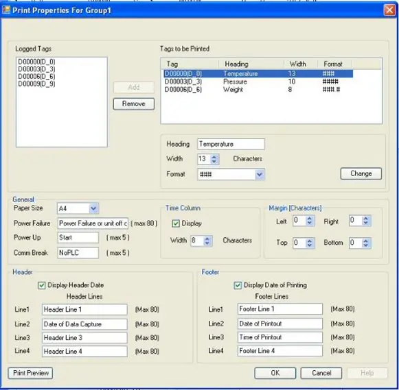
Definition of Terms:
- Logged Tags: this is a list of all of the tags that are to be logged for the selected Group. To print a tag, highlight (click) the tag, then click the Add button. This will add the tag to the ‘Tags to be Printed’ list on the right.
- Tags to be Printed: this is the list of tags that will be printed. A separate column is allocated for each tag with the option to create a heading, adjust the width of the column, select the number of digits (including decimal notation), and specify the data type. To edit these parameters, highlight each tag, adjust the parameters in the appropriate fields below, and then click the Change button. A tag can be removed from the list by highlighting the tag, then clicking the Remove button.
- Paper Size: at the time of this printing, only A4 paper size (8.3” x 11.7”) is available.
- Power Failure: This feature allows you to print a message (up to 80 characters) that indicates a power failure. When using the Logging with Run Time Frequency mode, during normal operation, the Data Logger will capture data according to the time interval set in the Frequency Tag. If there are periods of time in which power is removed from the HMC, it will not be able to capture data. To indicate periods of power loss on the print out, you can create a message that will print instead of the expected data.
- Power Up: This feature allows you to print a brief (5 character) label indicating when the HMC’s power was restored. This label will print just above the first data capture.
- Comm Break: If some of the tags to be printed are assigned to PLC registers, this feature allows you to print a brief (5 character) label if communications with the PLC are temporarily lost. If such a circumstance occurs, the printout will show the last valid data value read from the PLC register and this label.
- Time Column: Use this option to display the time of each reading. Make sure that you allocate enough characters to display the time in HH:MM:SS format.
- Margin: use these settings to reserve margins on the printout.
- Header: this option will print a header at the top of each page printed. Up to 4 lines (80 characters each) can be configured.
- Footer: this option will print a header at the bottom of each page printed. Up to 4 lines (80 characters each) can be configured.
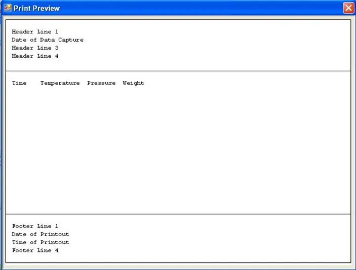
Click the Print Preview button to see how your printout will look:
Print Format when using all other logging modes except Logging with Run Time Frequency:
The print feature is available for all other modes of Data Logging (i.e. Power Up, Start/Stop Time, etc.) but has fewer options when formatting the printout:
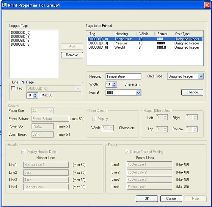
You can still select which tags you wish to print and create headings, change the width, display format, and data type.
You also have the option of setting the number of lines printed per page (up to 60) or you can use a targeted tag address if you wish to dynamically change the lines per page during runtime operation.
Start/End Print Time for the Data Logger
After you have configured the format of the printouts (using the Print Properties button), you need to determine the period of time that is to be printed. This is done by clicking the Start/End Time Tags for Printing tab in the Data Logger:
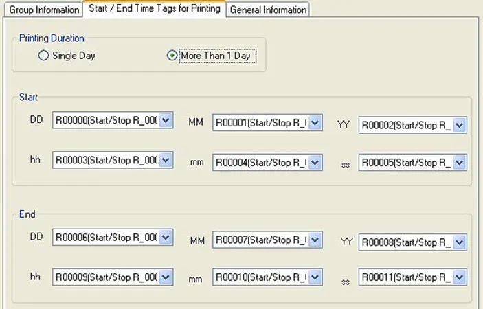
The Start/End date and time settings do not determine when the HMC will start printing to the serial printer. That is determined by configuring two Function Keys (or Advanced Bit Buttons) which, when pressed, will start and stop the Data Logger output to the serial printer. Rather these settings determine what part of the collected data is to be sent to the printer based upon the Date and Time recorded. For example, my Data Logger may have recorded data from three registers over a period of several days. But I only want to print a portion of this data, beginning on the specified Start Date/Time on this tab and ending on the specified End Date/Time settings. Or I may have a Data Group configured that gathers data over a 24 hour period every day but I only want to print the data collected between the hours of 7am and 8am. These settings are used for this purpose.
Printing Duration: this determines the number of days that the printing occurs.
- Single Day – this option is available only when ‘Logging with Runtime Frequency’ is selected as the logging mode. Enter the tag registers that determine the particular day (day of month, month, and year) of data that is to be printed. During operation, the HMC will print a report of all data collected within the 24 hour period of the day selected, when the Key Specific Task – Start Printing of Group# with Port# is pressed.
- More than 1 Day – this option is used to print all data collected for the selected data group during a specified time period. Rather than a single day’s worth of data, this option allows you to select multiple days based upon the values read from the tag registers assigned to the Start and End dates. During operation, the HMC will print a report of all data collected within the period selected, when the Key Specific Task – Start Printing of Group# with Port# is pressed.
Start/End Entries: these are the tag registers that the HMC reads to determine what the Start/End Date and Time (if More than 1 Day is selected) periods are. The HMC will read these registers whenever the operator presses the Key Specific Task – Start Print of Group# with Port# function key to initiate printing. Both 16-bit and 32-bit tags can be assigned to each register but only 16-bit is necessary. Data is interpreted by the HMC as unsigned integers with the following ranges:
| Tag | Description | Range |
|---|---|---|
| Start/End – DD | Day of month | 1-31 (1st day of month =1, …) |
| Start/End – MM | Month | 1-12 (Jan=1, …, Dec=12) |
| Start/End – YY | Year | 0-99 (last two digits of year) |
| Start/End – hh | Hour | 0-23 (24 hour format) |
| Start/End – mm | Minute | 0-59 |
| Start/End – ss | Seconds | 0-59 |
Note: once you have initially configured the Start/End Time Tags for Printing, if you wish to edit/change these settings at a later time, you must first click the Group# in the Groups box on the Group Information tab of the Data Logger, and then you must click the Print Properties button to review the printout settings. If you do not perform these steps first, then all selections in the Start/End Time Tags for Printing tab will be greyed out and cannot be edited.
Creating the Print Data Logger activation keys:
After you have configured how you wish the printout to look (see Formatting Data Logger Printouts), and what portion of the captured data to print (see Configuring Print Time for the Data Logger), the final step in setting up a serial printer to print Data Logger data is to configure activation keys. These activation keys are used to start/stop printing. The keys can be function keys (either global or screen-dependent) or touchscreen buttons (using the Multi-Task Single-State or Multi-Task Multi-State Button).
To create a Start/Stop Printing Data Logger key:
- Go to the configuration menu for a global or screen-dependent function key or the Multi-Task Button:
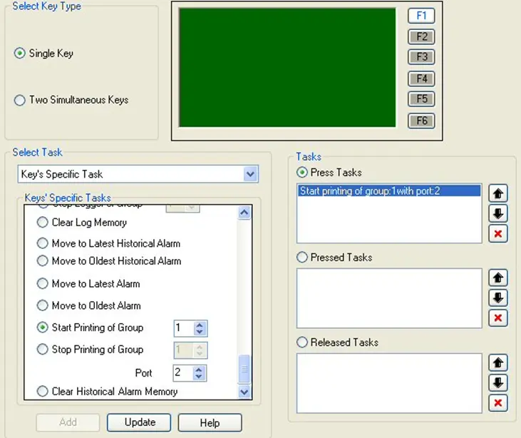
- Click single key option, then highlight the Function key (F1, F2 …) that you wish to use.
- Under Tasks, click Press Tasks.
- From the Select Task menu, select Key’s Specific Task.
- Click Start or Stop Printing of Group. Enter the Group # (1-4).
- Under Port #, enter the com port that the serial printer is attached to (Com1 or Com2).
- Click the Add button. Should appear in the Press Tasks section as shown above.
- Click the OK button (for Multi-Task buttons).
View Logged Data from the Internal Memory
There are several methods that you can use to see the data collected by the Data Logger for each group configured. The methods below apply only to the internal data log. For external data logs, configured to log data directly to an SD card, refer to the External Data Logger and the FTP Client section below.
- Historical Trend Graph – this method records values read from the Data Logger over the specified date/time. It then displays the data as a line graph. A maximum of four data points (channels) are represented on each graph. The Historical Trend Graph is the only option available to see data from the Data Logger on the HMC unit.
- Upload to a USB Flash drive – this method allows you to capture data in a CSV (Comma-Separated-Value) format as a data table which is stored on an attached USB Flash Drive to the HMC.
- Upload with the MAPware software – this method allows you to upload the collected data directly into the MAPware configuration software as a CSV file. This CSV file can then be viewed using the Tools > Display Logged Data option from the standard menu.
Using the Historical Trend Graph :
- Steps to create a Historical Trend Graph are covered in Historical Trends in the section on Trending Objects so they will not be repeated here. However, keep in mind that the Historical Trend Graph does not show real-time data – only data as recorded in the Data Logger.
- Use a global or screen-dependent function key or Multi-Task Bit/Word button configured as Key’s Specific Task – Refresh All Trends to ‘refresh’ or update the Historical Trend Graph after it is initially displayed on the HMC screen.
Use this object to display a historical trend graph that represents up to four tag registers. The Historical Trend differs from the Real Time Trend object in that the Historical Trend receives data from the Data Logger- it does not display real-time values taken from the PLC.
Uploading to a Flash Drive
A standard USB Flash Drive can be connected to the USB Host port on the HMC.
- Make sure that the USB Flash Drive has been formatted as FAT or FAT32.
- Although most USB Flash Drives should be acceptable, we have tested 1GB to 8GB memory from the following manufacturers:
- Transcend
- SanDisk
- Kingston
- PNY
- Sony
- Make sure you make a backup of all critical data on the USB Flash Drive before attempting to use it on the HMC
Insert the USB Flash drive into the USB Host port of the HMC. It makes no difference if the HMC is powered up when you insert the drive.
Note: whenever you start the download process to the USB Flash Drive, the HMC will temporarily not respond to touchscreen key presses until it has completed the download process. Screen data updates will also be affected. This is normal but we do recommend taking your HMC ‘offline’ while performing this operation. The time required to download varies depending upon the total size of the Data Log file but may take several minutes to complete.
Upload to a Flash Drive: Method 1 (HMC2000)
This is the first of three methods to upload data logs from the HMC unit.
Instructions: Upload to a Flash Drive: Method 1 (HMC2000)
Turn on USB trigger bit
Configure a quick button (Set Bit) to turn on internal tag “USB host menu trigger”.Select YES on confirm window
When the HMC displays the screen with this button, press it to see the image below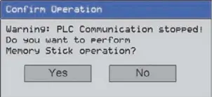
Confirm Download/Upload
After pressing ‘Yes’ at the last screen, a number of messages will display as the HMC attempts to read the USB Flash Drive. Eventually, the following message should appear: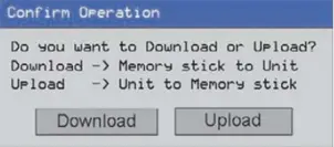
View and Select Options
Click UPLOAD to view the options available to you.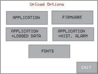
Click “Application+Logged Data”
For our purposes, we are uploading the application and the logged data, so select that option.The Application and Logged Data must be uploaded together, since we will be viewing the logged data through MAPware-7000.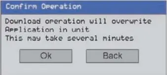
Click OK.
Click OK to start the Upload process. When done, a message appears indicating that the Upload was completed successfully – Press OK to continue.The message ‘Uploading Application file’ should appear along with a System Load Bar. After some time, another message ‘Uploading Logged Data file’ should appear. The entire Data Log file (size is 256KB, 512KB, 1024KB, or 2048KB depending upon memory allocated) is uploaded into the Flash Drive.Click OK than EXIT; HMC unit will reboot
Click OK. The Upload Option screen reappears. Click ‘Exit’ to leave this menu. The HMC will now reboot and run the project.Remove Flash Drive from HMC; insert into the PC
Remove the Flash Drive from the HMC and examine the files using your computer.Two files should be present:
HMCModel.mpl – this is the project application file that you can select and configure using the MAPware configuration software.
Logger_Data.bin – this is the Data Log file that the HMC uses internally to record all data collected using the Data Logger feature. To view the data, you must rename this file to Logger.bin and then copy this file into the main directory of MAPware (ex. C:\MapleSystems\MAPware7000).
Open MAPware, and select the “Display Logged Data” option.
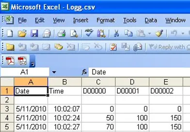
In MAPware, click Tools > Display Logged Data.The data is converted into a CSV file (Logg.csv) and displayed using Microsoft Excel.
Upload to a Flash Drive: Method 2: Create a Task
This is the second of three methods to upload data logs from the HMC unit: Configure the USB Data Log Upload task to download a particular data group (1-4) to the USB Flash Drive.
Instructions: Upload to a Flash Drive: Method 2: Create a Task
Initiate the Upload Task
The USB Data Log Upload task can be initiated in several ways:
Using a Multi-State Single/Multiple Task touchscreen button with the Press Task or Released Task.
Use the Power-On or Global Task option.
Use any of the screen-dependent tasks.
Use the USB Data Log Upload instruction (see Functions when Logic Block selected)
Use a USB Data Log Upload Task
When the USB Data Log Upload task is selected using a Function key, the following screen appearsBefore you Add the selected task to the Press Task field, you must select several registers that are used by the HMC during upload. All referenced tags must be internal memory of the HMC and must be 16-bit registers.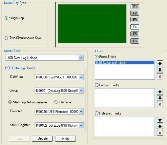
Select Date/Time
DateTime: this is the Start/End Date/Time tag registers that determine what portion of the Data Log file is uploaded to the USB Flash Drive. The HMC will read twelve consecutive registers beginning with the tag address referenced.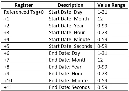
Select Group
Group: this is the tag register that the HMC reads to determine which Data Group to upload. Valid number: 1-4Select File Name (or Register)
Select a filename, or a set of registers to reference for the filename.Select ‘Start Register for Filename’ to reference four consecutive registers. These registers are interpreted by the HMC as ASCII characters (two characters per 16-bit register) to create a filename that is used by the HMC when uploading.
Select ‘Filename’ to manually enter the name for the upload file.
Select a Status Register
StatusRegister: the HMC will use this register to enter a status code number which can be used to communicate any errors during upload or status: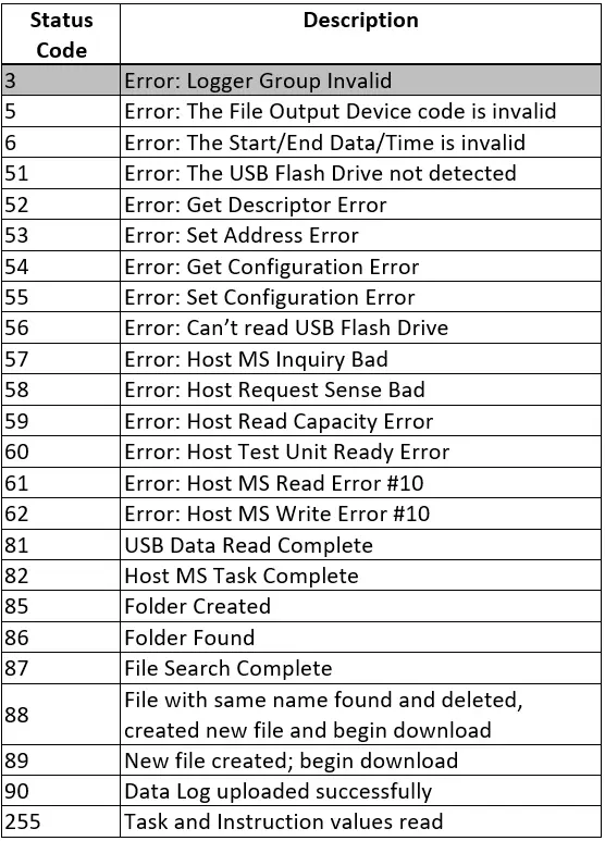
Click the ADD button
After you have selected appropriate tag addresses to use, click the ‘Add’ button to add the USB Data Log Upload task to the task list.Make sure you create a project screen that can be used to enter the correct values for each register usedEnter values for registers used.
During operation, go to the project screen that you created to enter the Start/Stop Date/Time.Remember that this is the portion of the Data Log that you wish to capture to the USB Flash Drive.Enter Group Number
Enter the Group# that you wish to capture.Enter File Name
Enter the name of the file (not required if you are using a predefined filename) for the USB Flash Drive upload. Up to 8 characters are allowed.Click the Function Key created earlier to initiate the Task
Next, activate download to the USB Flash Drive using the function key or task you created. Use the USB Status code register to provide status of the download.Tip: Create a Message Data object to display a message for each status code.After Download is complete, remove USB from HMC and connect to your PC.
After the download is complete, you can remove the USB Flash Drive from the HMC and connect it to your computer. You should see a folder with the model name of the HMC you are using. Click the folder to see the CSV files that you uploaded: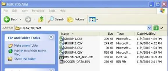
Open the CSV File
Click the CSV file to load the file into Microsoft Excel: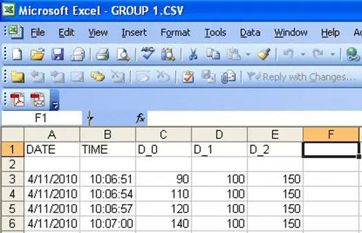
Upload with the MAPware software
The third method to upload data log files is direct via the MAPware-7000 Software itself; see the steps below.
Instructions: Upload with the MAPware software
Open MAPware-7000
Start MAPware, and then close out any project that is automatically loadedOpen the upload Window
Click Project > Transfer > Upload from the standard menu. The Upload From Device dialog box is displayed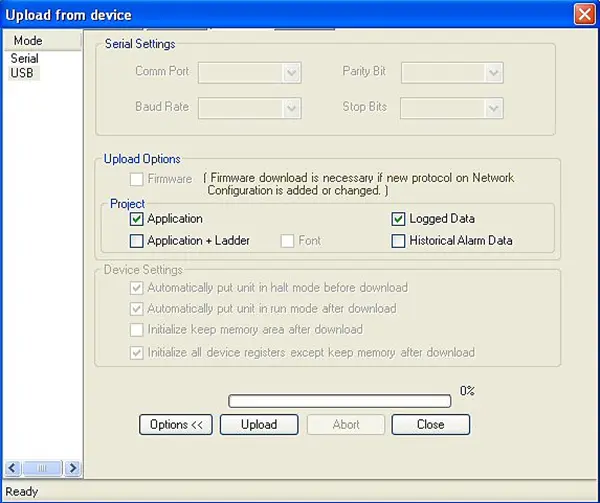
Click “Logged Data”
Select the “Logged Data” check box in the Project section, and click Upload.Click OK.
Click the OK button to begin the upload process.Click Close when done
Once the upload is completed, click the Close button.The Data Log file is automatically stored onto your computer in the same directory that the MAPware software is located (default is C:\Maple Systems\MAPware7000) as “Logg.csv”. To view this file, click Tools > Display Logged Data from the MAPware standard menus. The file will display using Microsoft Excel (see enclosed image)