
Overview
Sequential Function Chart (SFC) is a graphical logic editor. The SFC editor models machine operation in the form of a flow chart or state diagram. The programmer defines what happens in each step or state, the conditions to transition from one step to the next, and how steps are connected to one another. Graphical steps are used to represent stable states, and transitions describe the conditions and events that lead to a change of state. Machines that perform a sequence of repetitive operations over time are well suited to be programmed using SFC.
The workbench fully supports SFC programming with several hierarchical levels of charts: i.e. a chart that controls another chart. Each SFC program may have one or more “child programs”. Child programs are written in SFC and are started (launched) or stopped (killed) in the actions of the parent program. A child program may also have children. The number of hierarchy levels should not exceed 19. Working with a hierarchy of SFC charts is an easy and powerful way to manage complex sequences and save run time performance.
The basic building blocks of a SFC logic block are:
- Steps
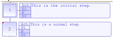
Steps define the actions carried out by the program. The programmer can define actions that take place:
- When a step is entered
- While in the active step
- When the active step is exited
- Transitions

Transitions define the conditions that need to be met in order to move from the current step to the next. The transitions act as gates. Until the transition condition is met, the step connected before (above) the transition remains the active step.
- Divergences/Jumps
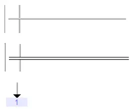
Divergences and jumps determine how steps and transitions connect together. The selection of a divergence type can allow:
- One step to connect to multiple transitions. This allows selection between several steps: the transition condition that is met first determines which of the step sill become active next.
- One transition to execute multiple steps in parallel (i.e. at the same time).
- A series of steps, or network of steps to be repeated (using a jump)
- A series of steps to converge into a single step.
The task of the SFC programmer is to connect these building blocks together into a network modeling the functionality of the process being controlled.
Adding Logic to the Block
Building a Simple SFC Diagram
For those new to SFC programming this section will cover the minimum steps needed to create a very simple SFC diagram in the editor.
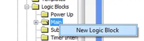
To create a new SFC logic block right-click the Main folder within the Logic Blocks folder of the Project Tree.
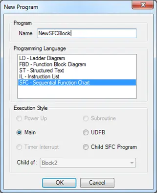
Enter a name for the logic block and select SFC – Sequential Function Chart for the programming language, then click OK to create the new block.
The entry point to any SFC diagram is the initial step. MAPware-7000 will create and place the initial step in the top left corner when a new SFC logic block is created:
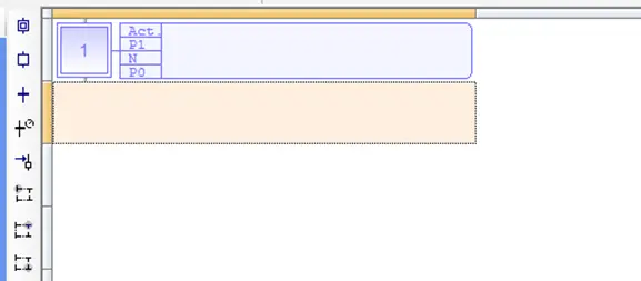
The rule for exiting a step is that it must connect to either a transition or a divergence; a step cannot connect directly to another step. To keep this chart simple, we will use a transition. Click the editor square below the initial step to select it. The selected square will be highlighted in a light orange color as shown in the screen shots. Then click the Transition icon in the Quick Select menu: . This will place a transition in the selected square.
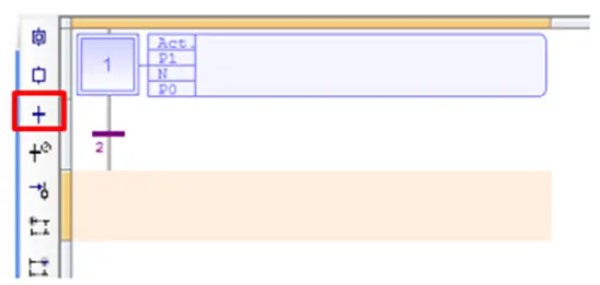
Now that we have a transition, we can add another step. The editor should automatically select the square below the transition as shown in the screen shot above. With this square selected, click the Step icon ( ) from the quick select menu to add a step to the chart.
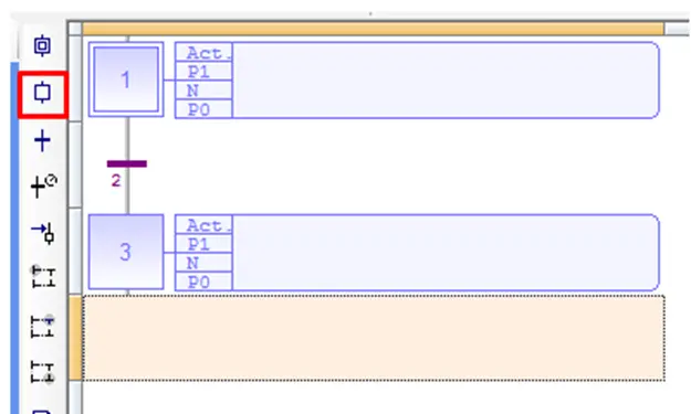
Note that steps and transitions are designated with a number by the editor. Click the transition icon ( ) to place the exit transition for Step 3.
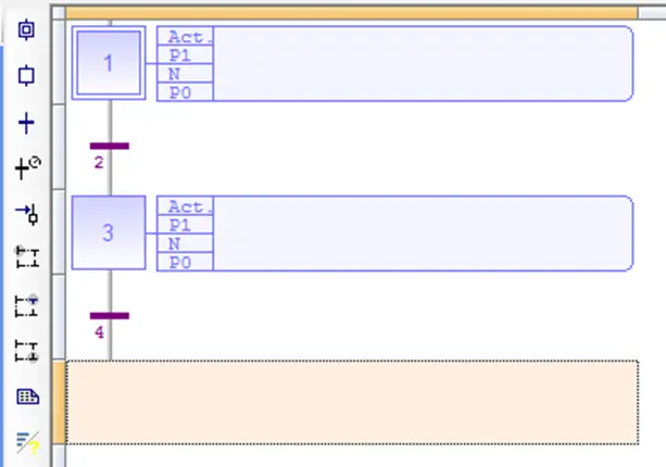
Finally, complete the chart with a Jump back to the initial step. Click the Jump icon to place the Jump below Transition 4.
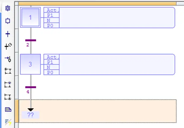
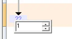
The Jump is placed with ?? for the destination. To tell the Jump where to jump to, double-click the question marks and enter ‘1’ to direct the jump back to the initial step.
That completes the simple SFC.
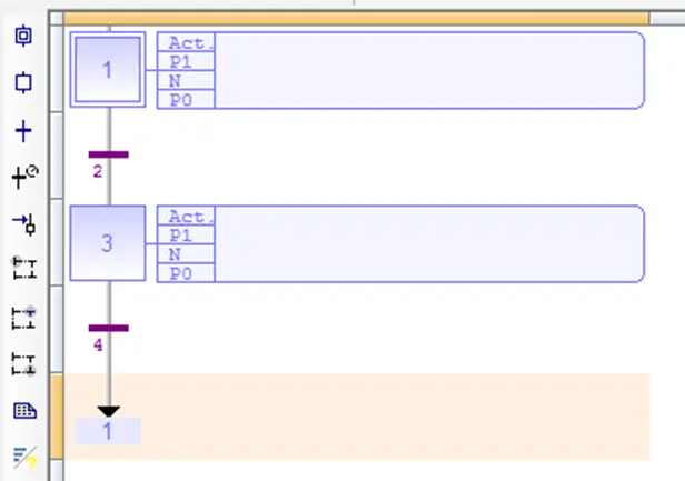
The active step will simply alternate between Step 1 and Step 3 in an endless loop. Of course, the steps do nothing and the transitions are always true. So, while this logic block will work, it is not particularly useful. Use the sections below to configure the steps and transitions.
Steps
A step represents a stable state and defines what a program does in a given state. Each Step contains four different action types that can be configured independently:
- Action: This is a list of actions that operate as long as the step is active. Actions can be simple boolean or SFC actions that consist of assigning a boolean variable or controlling a child SFC program.
- P1: This is an action block that is executed once when the program is activated. Action blocks can be programmed in any of other IEC languages (FBD, LD, ST, or IL).
- N: This is an action block that operates continuously while the step is active. Action blocks can be programmed in any of other IEC languages (FBD, LD, ST, or IL).
- P0: This is an action block that operates once when the step is deactivated (i.e. the transition condition below the step becomes true). Action blocks can be programmed in any of other IEC languages (FBD, LD, ST, or IL).
Within the SFC program, you can test the step activity by specifying its name (“GS” plus the step number) followed by “.X”. Example: GS3.X Is TRUE if step 3 is active (expression has the BOOL data type).
You can also test the active time of a step by specifying the step name followed by “.T”. This is the time elapsed since the activation of the step. When the step is de-activated, this time will remain unchanged. It is reset to 0 the next time the step becomes active. Example: GS3.T is the time elapsed since step 3 became activate (expression has the TIME data type).
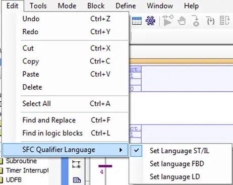
The programming language for the P1, N, and P0 action blocks defaults to Structured Text/Instruction List. To change the desired programming language, select Edit > SFC Qualifier Language from the main menu.
In addition, each step has a Notes section containing a simple text editor that allows notes to be entered describing what the step does.
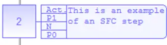
You can get a quick idea of which actions are configured for a step from the step’s graphic in the SFC editor:

Actions that have been configured are shown in a darker color, while un-configured actions are lighter. Notes entered in the step’s Note editor appear in the label to the right of the list of actions. Step 3 above has logic in both the N and P0 action types.
To open the editor for a given step, simply double-click the step. The SFC editor window will split into two panes.
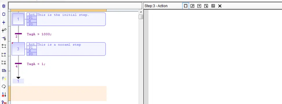
On the left, the SFC diagram is still visible. On the right, the editor for the step is displayed. Zooming in on the top of the editor pane shows the following:

In the top left of this editor pane, the step number is shown. The open editor window is listed immediately after. In this case it shows the step is number 3, and the Action editor is open.
To the right of this there are six clickable icons. These icons function as follows:
- Open the Action editor for the action
- Open the P1 action block editor (P1 = executed once when the step is activated)
- Open the N action block editor (N = executed while the step is active)
- Open the P0 action block editor (P0 = executed once when the set is de-activated)
- Open the Notes text editor to type in a comment describing what the step is supposed to do
- Close the editor window
Click the N action icon, Note how the Quick Select Menu for the ST Editor is displayed on the left edge of the editor pane:
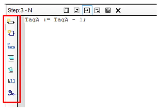
This is because this window defaults to using the ST Editor. The Quick Select Menu and Instruction List can be used to build statements just as if this were a regular ST logic block. To change the programming language for the individual step, select Edit > SFC Qualifier Language from the main menu.
Refer to the previous sections on the different editor languages to configure the P1, N and P0 actions.
Transitions
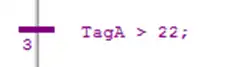
Transitions represent a condition that changes the program activity from one step to the next. Each transition must be completed with a condition that evaluates to either TRUE or FALSE to indicate if the transition can be crossed. The condition is a boolean expression that can be programmed either in ST or LD language. Similar to a step, the editor for a transition is opened by double-clicking the transition graphic in the SFC diagram.
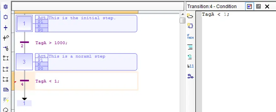
The transition editor only has a Condition Editor for the transition condition and a text editor to enter notes for the transition.

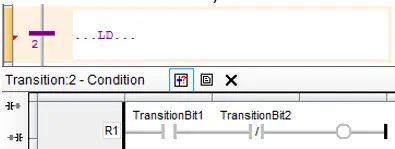
To enter the transition condition editor click the condition editor icon ( ). This will open a ST editor by default as shown above. To change to the LD editor, select it from the Edit > SFC Qualifier Language menu.
The transition condition is a very simple program. If there are effects that need to occur when one step is exited and another is entered, the P0 and P1 step action blocks are the proper places to implement that logic. Transition conditions should simply control when a move to the next step occurs.
The Transition condition must consist of a single ST statement or rung of LD code that evaluates to a single Boolean value.
Valid Structured Text Transition Condition Expressions
Because only a single statement is used, the ‘;’ character is optional when using Structured Text. The expression can be composed of multiple expressions, but only one statement is allowed.
Expressions that evaluate to Boolean values generally are expressions that use comparison operators or Boolean logic operators. The table below lists the ST operators that are valid to use for transition conditions:
| Operator | Name | Description |
|---|---|---|
| func() | Function call | Values are assigned to parameters. Function is executed. Expression evaluated to returned value. |
| NOT | Complement | Returns the opposite logical value of the Boolean operator on the RHS. |
| < | Less Than | True when LHS is less than the RHS, false otherwise. |
| > | Greater Than | True when the LHS is greater that the RHS, false otherwise |
| <= | Less than or equal | True when the LHS is less than OR equal to the RHS, false otherwise |
| >= | Greater than or equal | True when the LHS is greater than OR equal to the RHS, False otherwise |
| = | Test for equality | True if RHS has the same value as the LHS, False otherwise. |
| <> | Test for inequality | True if the RHS does not have the same value as the LHS, False otherwise |
| &, AND | Boolean AND operation | True if LHS AND RHS are true, false otherwise |
| XOR | Exclusive OR | True if the LHS is true while the RHS is false, or the LHS is false while the RHS is true. False if both LHS and RHS are true. False if both LHS and RHS are false. |
| OR | Boolean OR | False if both LHS AND RHS are false, true otherwise. |
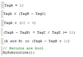
The expression used for the transition expression must evaluate to a Boolean value, however, the expression can be composed of operands that are themselves expressions. In this case, the expressions making up the operands are not limited to using the above operators. For example, the expressions below are all valid transition expressions:
Using Function Calls as Transition Conditions
Note that a function call is a valid transition condition expression. The requirement is simply that the function call evaluate to a Boolean value. That is, the function must return a single Boolean value. This is appropriate for complicated calculations that can’t be done in a single statement.
A subroutine can be defined, and the subroutine can contain any number of statements, or be constructed using LD or FBD as required. The only requirement is that the subroutine must return a single Boolean value.
When calling the subroutine, do not assign the return value to a tag. The assignment operator is not allowed in transition conditions.
Using Ladder Logic for Transition Conditions
In LD language, the condition is represented by a single rung. The coil at the end of the rung represents the transition and should have no symbol attached.
Divergences
Divergences are what allow SFC programs to branch. Using divergences, one step can lead to multiple steps, a program can select between steps, and multiple steps can converge back to one step. The Quick Select Menu contains options for three types of divergences that are used for different purposes:
- Type X divergence – Used to initiate or terminate a SFC branch:

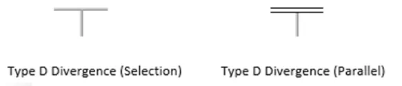
- Type D divergence – Used when initiating a SFC branch to provide a connection point to the right of a Type X divergence and above either a transition (in the case of a selection branch), or above a step (in the case of a parallel branch).
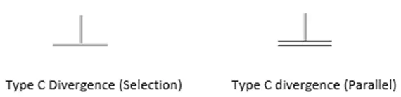
- Type C divergence – Used when terminating a SFC branch to provide a connection point to the right of a Type X divergence and below a step or a transition.
The SFC snippet below shows where the different divergence types are used in a typical branch:
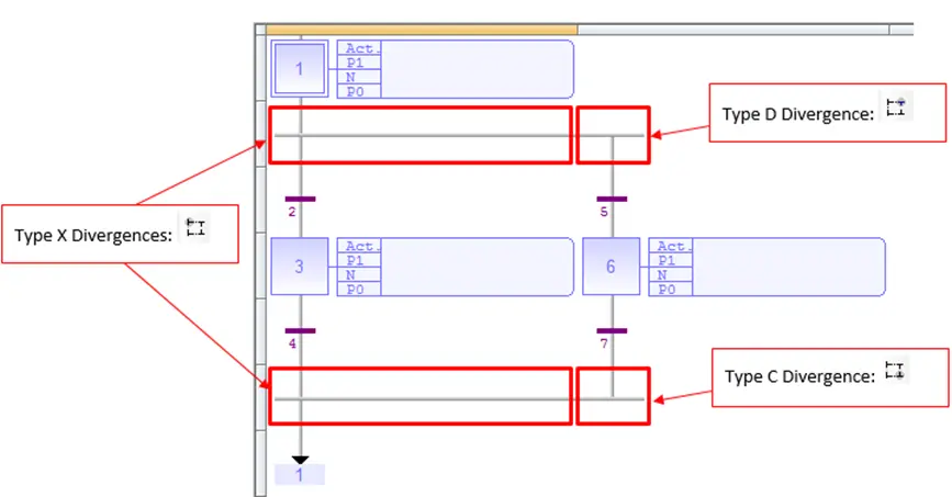
Multiple D and C type divergences can be connected to the right of an X type divergence in order to add more vertical branches to the chart:
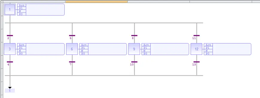
There are two types of branches possible in SFC diagrams:
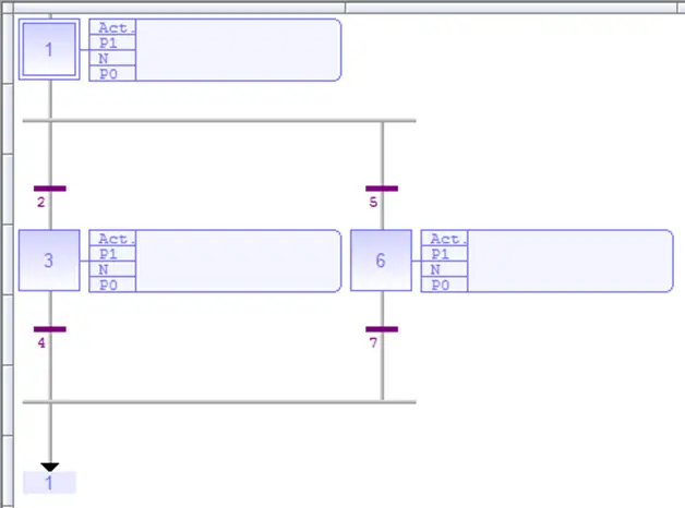
Selection Branches
– In a selection branch, one of several alternative steps is executed depending on which transition condition becomes true first. Transition conditions are evaluated from left to right. If multiple transition conditions become true at the same time, the step furthest left will be activated.
Parallel Branches
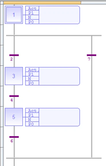
– In a parallel branch, all of the steps connected to the branch become active simultaneously (in the example below, steps 4 and 6). That is, they are executed at the same time. This is similar to having several logic blocks in the main folder. Each block is executed once per PLC scan. Similarly, each step connected to a parallel branch will be executed each PLC scan, provided the parallel branch is active.
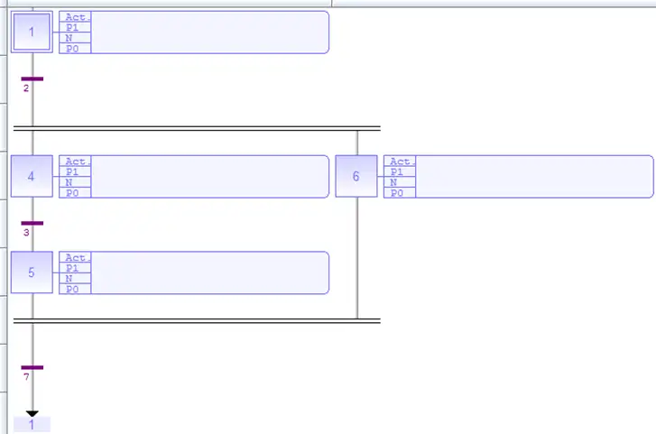
Processing of parallel branches may take different timing according to each branch execution. The transition after the convergence (transition 7) is crossed when all the steps connected before the convergence line (last step of each branch, 5 and 6) are active. The transition indicates a synchronization of all parallel branches.
If needed, a branch may be finished with an empty step (with no action). It represents the state where the branch “waits” for the other ones to be completed.
To switch from one type of branch to another, use the Swap Item Style quick select menu item . Notice how a single branch can only have one style. The entire branch will change type when the Swap Item Style icon is pressed.
Quick Select Menu Options
In the SFC menu the Quick Select Menu has the options described in the following sections.
Initial Step < I >
This item places an initial step in the SFC Editor.
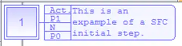
By default when a SFC block is created, it will have an initial step in the top left square. SFC diagrams must have at least one initial step. The initial step will be the active step when the SFC block is first evaluated.
Step < S >
Insert a step.
Select the square in the editor where the step is to be placed. Then click this icon to place the step. Steps must be placed after a transition (or a divergence connected to a transition), and steps must be followed by transitions (or a divergence connected to a transition).
See the Configuring Steps section for information on configuring a step once it is placed.
Transition < T >
Place a transition.
Select the square in the editor where the transition is to be placed then click this icon to place a transition. Transitions must be placed between steps or divergences/jumps that connect to steps. A transition cannot connect to another transition.
See the Configuring Transitions section for information on configuring the transition once it is placed.
Set Timer on Transition
Use this option to place a timer transition.
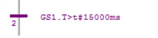
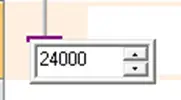
Select the location in the editor where the timer transition is to be placed, then click this icon. A text box will appear where the preset time (in milliseconds) can be entered. This is the time that the step above the transition will be active.
A timer will automatically be created for the timer transition. The timer begins counting up once the step directly above the transition becomes active. When the timer counter ( GSX.T ) becomes larger than the preset the transition condition becomes true. The transition condition is automatically formatted to accomplish this.
Jump < J >
Place a Jump.

A Jump points to a step without actually being connected to it. Since a Jump connects to a step it must be added directly after a transition. Click the square in the editor where the jump is to be placed, then click this icon to place the jump.
When first placed, the jump will appear with question marks for the destination.

Double-click the question marks to select the destination step.
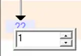
Once configured, the destination can be changed by double-clicking the destination step number again.
Divergence (X) < X >
Place an X type divergence.
To place an X type divergence click the square in the editor where the divergence is to be placed, then click this icon.
Use this type of divergence to start a SFC branch, or to converge several branches. Use the Swap Item Style quick select option to switch between Selection and Parallel branch styles.
See the Divergences section above for more information.
Divergence (D) < D >
Place a D type divergence
A D type divergence is used to add a vertical branch to the right of an X type divergence. Multiple D type divergences can be added to create multiple vertical branches.
To place a D type divergence select the block of the SFC editor where the divergence is to be placed then click this icon.
Use the swap item style quick select menu option to switch between selection and parallel branch styles.
See the Divergences section above for more information.
Divergence (C) < C >
Place a C type divergence
Despite the name a C type divergence is used to converge a series of vertical SFC branches. The C type divergence should be placed to the right of an X type divergence. One C type divergence should be used for each vertical branch that is to be converged.
To place a C type divergence select the block of the SFC editor where the divergence is to be placed then click this icon.
Use the swap item style quick select menu option to switch between selection and parallel branch styles.
See the Divergences section above for more information.
Insert Comment
A comment is simply a text box placed in the SFC diagram that is used to annotate the chart.
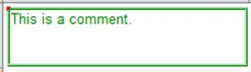
To place a comment select the editor square where the comment is to be placed, then click the Insert Comment icon.
To enter text for the comment Double-click in the comment box and type the text in the editor window.
Change Display
This controls how steps and transitions are shown in the SFC editor.
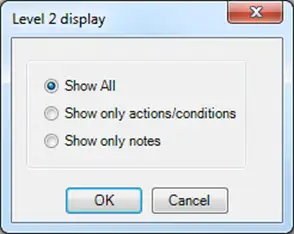
Options are:
- Show All – This is the default configuration. For steps, a list of all action types are shown with ones that are used highlighted in a darker shade. The notes are shown to the left of the list of actions. For transitions the condition is shown.
- Action Only – This option shows only the Action configured in the step, and the condition configured for a transition. Notes are not shown.
- Show Only Notes – Only shows notes. The action list is hidden in steps. And the notes are shown for transitions.
Swap Item Style
Use this option to toggle the style between a selection branch and a parallel branch
To use the option select the X Type divergence that terminates the branch, then click this icon.
Note that the entire branch will change when this option is used.
For more information on the difference between selection and parallel style branches refer to the Parallel vs. Selection Branches section above.
Renumber
This option will automatically re-assign numbers to all of the elements in the SFC. Simply click this option to auto number the elements.
Note: To renumber an element the editor for that element must be closed.
Elements can be manually assigned numbers using the Edit Reference option below.
Edit Reference
Used to change the reference number of an SFC element. Before using this option, the editor for the element must be closed. A red indicator in the top left corner of the element indicates that the editor for that element is open:
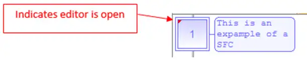
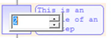
Select the element to change and click the Edit Reference icon. A text box appears where the new reference number can be entered.
Show One Qualifier in Level 2
This option is used to change the view of the editor window for editing step actions. This is the default setting. In this mode the SFC editor is split into two panes. The left pane shows the SFC diagram, and the right displays an editor for an action:
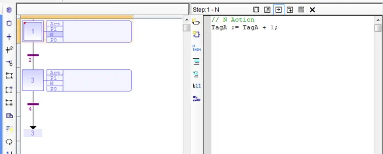
The user must select the action they want to edit using the icons at the top of the editor pane:
Show/Hide Split Window in Level 2
This option is used to change how the editor window for a step is displayed. In this mode, when a step action editor is opened the SFC editor window is split into three sections. The left pane of the editor window continues to display the SFC diagram. The right section is reserved for the action editor. The editor can itself be divided into two sections. When first opened the editor pane still only shows one editor, however the user can click another action icon to split the right pane in two:
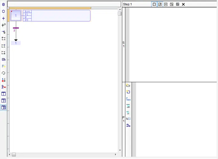
When two actions types are open for editing the icons corresponding to those editors are highlighted:

And a bar along the left edge of the editor pane indicates which action is being edited.
Clicking an open icon that is open will close the editor pane for that action.
Show All Qualifiers in Level 2
This option is used to change the view of the action editor for steps and transitions. This option is similar to the Show/Hide Split Window in Level 2 option, but the editor window can contain up to five splits so that all action types can be edited at the same time:
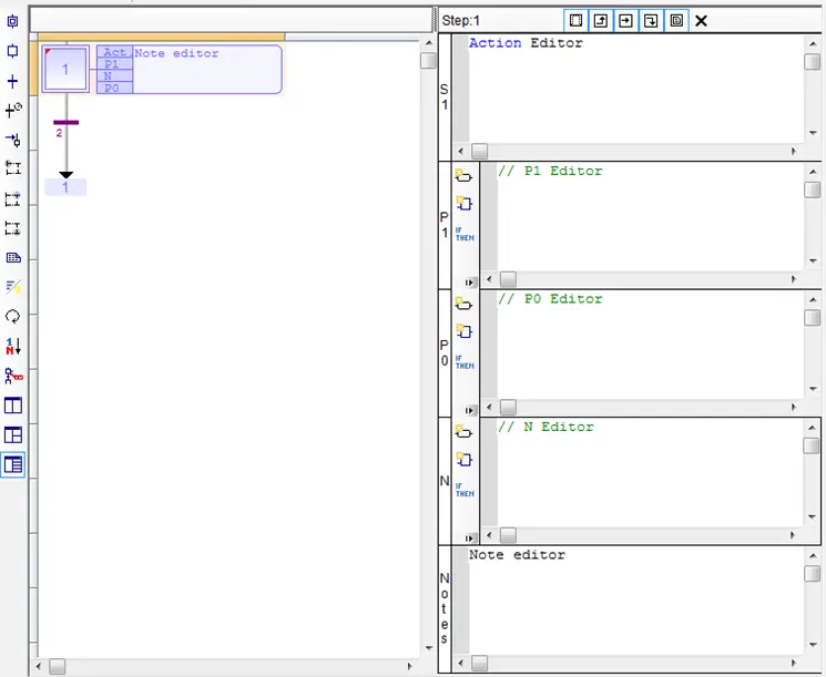
Using this option the SFC diagram is still displayed on the left and the editor(s) are displayed on the left. As the user clicks on the action icons in the editor pane the editor is split as needed. Open editor icons are highlighted, and a bar on the left edge indicates the action that is being edited.
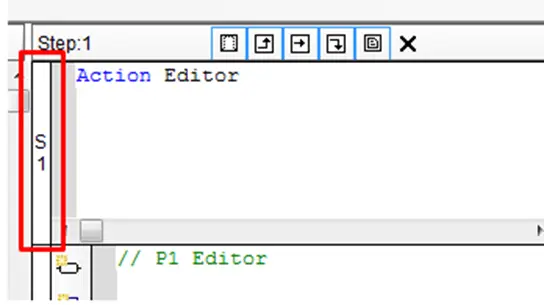
When the icon for an open action is clicked on, the split for that action is closed.
Quick Select Menu Keyboard Short Cuts
In the SFC editor, many of the items in the quick select menu are bound to keyboard shortcuts. Pressing the shortcut key is equivalent to clicking the corresponding quick select menu option. Using the keyboard short cuts can make editing SFC charts much faster.
The headings of the Quick Select Menu Options sections below list the quick select key in brackets (e.g., < I > means ‘I’ is the quick select key to place an Initial Step ).
Quick select shortcut keys are not case sensitive.
The following chart lists all of the quick select key bindings for quick reference.
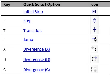
In addition to these quick select keys, the following hints help to edit SFC diagrams quickly using the keyboard:
- The arrow keys can be used to select a particular location on the editor.
- Using the arrow keys with <shift> held down will select a series of editor blocks.
- Cut, Copy and paste function can be done using < CTL > + < X >, < CTL > + < C >, <CTL > + < V >, respectively.
- The delete key can be used to remove items.
Child SFC Programs
Each SFC program may have one or more “child programs”. Child programs are written in SFC and are started (launched) or stopped (killed) in the actions of the parent program. A child program may also have children. The number of hierarchy levels should not exceed 19.
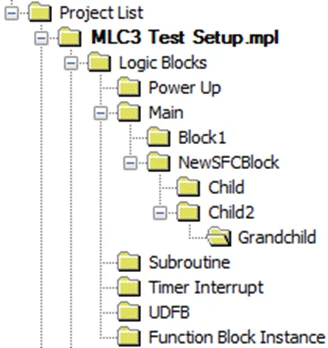
When a child program is stopped, its children are also implicitly stopped. When a child program is started, it must explicitly in its actions start its children.
A child program is controlled (started or stopped) from the action blocks of its parent program. Designing a child program is a simple way to program an action block in SFC language.
Using child programs is very useful for designing a complex process and separate operations due to different aspects of the process. For instance, it is common to manage the execution modes in a parent program and to handle details of the process operations in child programs.
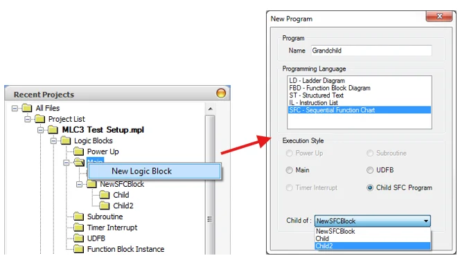
To create a Child SFC Program, right-click the Main folder in the Project Information Window and select New Logic Block. Select SFC – Sequential Function Chart for the Programming Language, Child SFC Program for the Execution Style, and use the Child of dropdown to select an existing SFC logic block as the parent (controlling) block.
Controlling an SFC Child Program
Controlling a child program is achieved by specifying the name of the child program in a step in its parent program. Below are possible qualifiers that can be used in the Action block section for handling a child program. In the following table, ChildProg represents the name of the child program:
| Qualifier | Description |
|---|---|
| ChildProg (N); | Starts the child program when the step is activated and stops (kills) it when the step is de-activated. |
| ChildProg (S); | Starts the child program when the step is activated. (The child program continues running until it is explicitly stopped elsewhere.) |
| ChildProg (R); | Stops (kills) the child program when the step is activated. (All active steps of the child program are deactivated) |
Alternatively, you can use the following statements in a P1, N, or P0 action block programmed in ST language. In the following table, prog represents the name of the child program:
| Statement | Description |
|---|---|
| GSTART (prog); | Starts the child program when the step is activated. (Inital steps of the child program are activated) |
| GKILL (prog); | Stops (kills) the child program when the step is activated. (All active steps of the child program are deactivated) |
| GFREEZE (prog); | Suspends the execution of a child program. |
| GRST (prog); | Restarts a program suspended by a GFREEZE command. |
You can also use the “GSTATUS” function in expressions. This function returns the current state of a child SFC program:
| Statement | Description |
|---|---|
| GSTATIS (prog); | Returns the current state of a child SFC program: 0: program is inactive 1: program is active 2: program is suspended |
Note: When a child program is started by its parent program, it keeps the inactive status until it is executed (further in the scan cycle). If you start a child program in a SFC chart, GSTATUS will return 1 (active) on the next scan cycle.
SFC Best Practices
The general principle of an SFC is that the activated Step(s) follow a well-defined path through the chart. Given the state of the system, which governs the transitions, it should be clear what step(s) will be active at any given time. The rules below will help avoid compile errors and logical errors:
- A step must connect to a transition and a transition must connect to a step.
- A parallel branch should have a transition before the branch point, and have one transition for the entire branch.
- A selection branch should have transitions after the branch point and should have one transition for each step attached to the branch.
- Any branch should have a corresponding convergence of the same type.
- Jump instructions should not be used to exit parallel branches.
- Generally, keep SFC diagrams simple. Use function calls etc. to construct complex operations out of simple building blocks.
SFC Design Patterns
Using the rules from above there are some common design patterns that are useful in creating SFC logic.
A Simple Loop
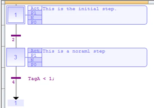
Loops are created using a series of steps and transitions, which end with a jump back to the step and the beginning of the loop.
Selection
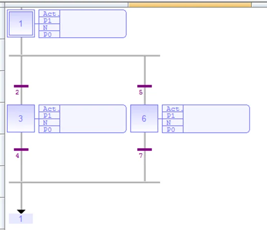
Selection allows the program to select between several divergent paths.
Parallel or Simultaneous Steps
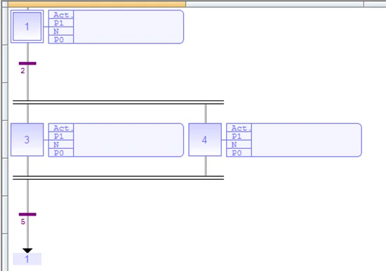
Allows multiple actions to take place at the same time.
Loop
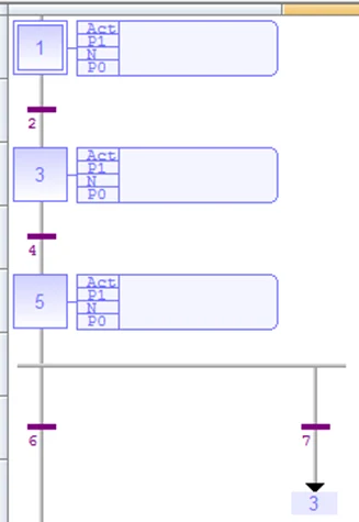
This pattern can be used to emulate a For or a While loop.
Skip
This sequence is used to short circuit a series of steps is a particular condition is met. It functions similar to an IF statement.
By combining these building blocks, an arbitrarily complex SFC can be constructed.