

Introduction
What is IEC 61131-3?
IEC 61131-3 is a section of an International Electro-Technical Committee (IEC) standard that provides a definition for implementing PLC programming software. The standard was first introduced in 1993 as the result of an effort to standardize the myriad PLC logic editors in the automation market place. The goal of the standard is to give automation professionals a familiar environment and set of tools to create PLC programs across vendor platforms. MAPware-7000 has editors implemented for all five programming languages defined by the standard. This manual will give you all the information you need to put these powerful tools to use.
Available Languages
The standard defines five unique programing languages. Editors for each of these languages are available in MAPware-7000. Details on using each of the editors are given in the chapters that follow. The Languages are:
- Ladder Diagram (LD) – Graphical language that simulates an electrical circuit; program instructions are attached as discrete elements in the circuit and are executed when “energized” (Chapter 4)
- Function Block Diagram (FBD) – Graphical language based on logic diagrams. Functions are represented by blocks; complex operations can be built by interconnecting function blocks (Chapter 5)
- Structured Text (ST) – Text based programming language. Programs are built using keywords, operators and function calls. (Chapter 6)
- Instruction List (IL) – Text based procedural programming language (Chapter 7)
- Sequential Function Chart (SFC) – Graphic programming language in which program execution is modeled as a flow chart. Programs are developed by adding blocks to the flow chart (Chapter 8)
The logic created using these languages is composed of discrete instructions or logic blocks. The available instructions are documented in the MAPware-7000 help file. In MAPware-7000 Double-click a particular instruction in the Instruction List to open that instruction’s help file entry.
The Editor Window
Let’s take a quick tour of some of the aspects of MAPware-7000 that are unique to an IEC 61131-3 project.
Projects created using IEC 61131-3 programming mode contain a Project Information Window that allows easy navigation to various parts of the project. When a new project is created it contains a default logic block named Block1.
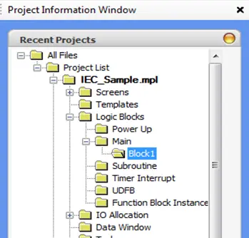
Clicking the folder for Block1 in the Project Information Window displays the editor for that block. The default logic block uses the Ladder Diagram editor, so the Ladder Diagram editor is displayed when the Block1 folder is selected in the Project Tree:
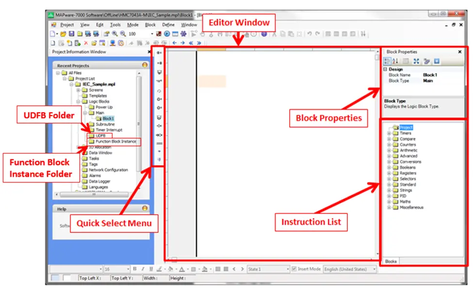
The parts of this window specific to the Ladder Diagram editor are covered in Chapter 4. Elements common to all of the editors are:
- Block Properties – Displays the name and Execution Type of the block.
- Instruction List – Lists all of the available instructions for the project. Instructions are categorized according to functionality. Expand the node for a given category to see individual instructions. To select a particular instruction simply click and drag it into the editor window. Subroutines and UDFBs (Function Blocks that users create) will appear under the Project folder of the instruction list once they are defined. Information on how to configure and use a given function block is available in the help file. To access the help file entry for any of the blocks in the instruction list simply double-click the instruction.
- Editor Window – This is where the logic is defined. It displays the graphical or text representation of the logic program.
- Quick Select Menu – The options available on this menu depend on the editor in use but provide quick access to common program elements. Click the location in the editor where you want to place the element then click the element in the quick select menu to place it in the editor.
- UDFB Folder – This folder contains the definitions for User Defined Function Blocks. To add or edit a UDFB, click the block name in this folder. To use a UDFB in another logic block, select it from the Project folder of the Instruction List.
- Function Block Instance Folder – This folder contains a list of all the Function Block Instances in the project. Each block can have multiple instances each instance will have its own private set of data to work with. Thus one type of function block can be utilized for multiple purposes in the project.
Logic Blocks and Execution Style
Programs created using the above editors are organized into discrete units called Blocks. The job of the programmer is to create logic blocks, define what they do and how they interoperate with each other to model the operation of the system they are building. A MAPware-7000 project can contain many blocks; each created using any of the various editors. In addition to the language used and the logic they contain, blocks are differentiated by Execution Style. Execution Style determines when and how the block is executed. The available Execution Styles are:
- Power Up
- Main
- Subroutine
- Timer Interrupt
- User Defined Function Block (UDFB)
When a new logic block is created, the language to be used and the Execution Style are specified:
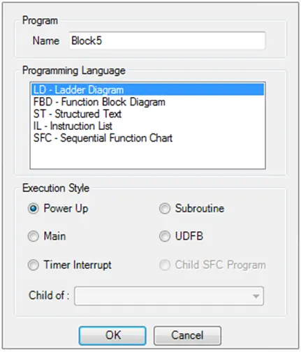
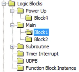
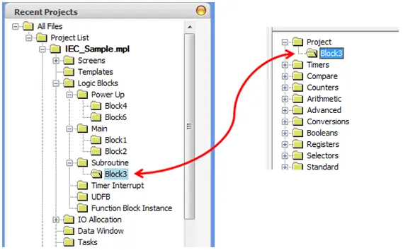
After the block is created, the Execution Style cannot be changed. The current Execution Style of a logic block is indicated by the block’s location within the Logic Blocks folder of the project tree:
To change the programming language of a block after it has been created, open the selected logic block in the editor window and select Tools > Convert Program > To […] from the main menu. It is not possible to convert to or from the Sequential Function Chart language, but all other languages are options. The converted code may need minor edits to compile.
The following sections give more detail on how the various Execution Styles operate and when to use them.
Power Up block
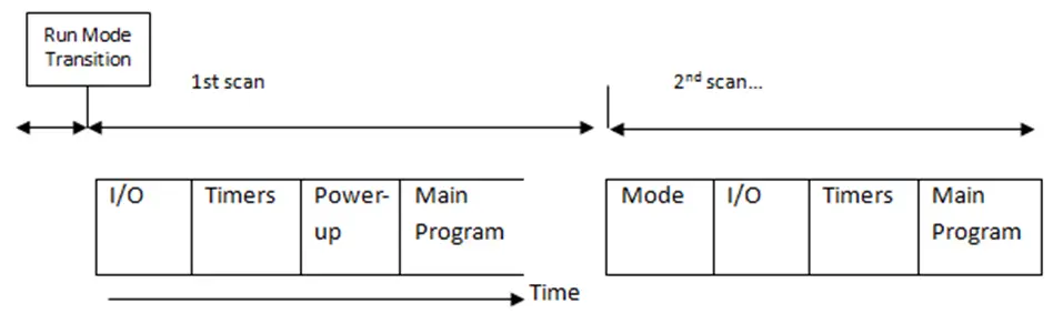
If Power Up blocks are present, they are executed once at the beginning of the first scan (before main block execution). Therefore, Power Up blocks can be used to set initial values into registers.
The figure below shows the first scan operation:
Main Program block
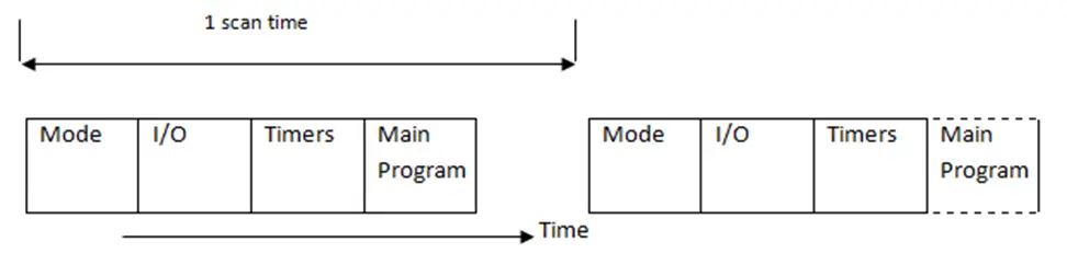
Main program blocks are the core of the user program. They are executed once during each scan.
Multiple logic blocks can be created (up to 256) and used as Main Program blocks. During execution, the HMC starts with the first block listed. When completed, it will execute each block in sequence. The figure below shows a typical scan sequence:
Where:
- Mode- determines mode of operation (Run, Halt, etc.)
- I/O- update and process all inputs and outputs
- Timer- update all running timers
- Main Program- all logic blocks created under Main
The length of a scan is not deterministic. It depends on what blocks are executed etc. If a more reliable execution time is required use a timer interrupt routine.
Subroutines
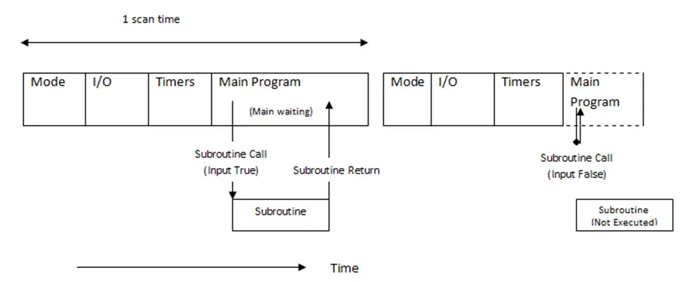
Subroutines operate the same as the main program except they are not executed unless specifically called on by another logic block. Subroutines are useful when you have a set of commands that should be executed only under certain conditions. A maximum of 256 subroutines can be created (dependent upon total memory available).
When a block is created as a Subroutine block, it will appear in the Instruction List as a function block that can be used in another block:
To execute the subroutine, select the instruction and add it to a main logic block. When the input condition to this instruction is true the Subroutine will be executed:
Timer Interrupts
Timer interrupt logic blocks are given the highest priority when the MAPware-7000 program is executed. The timer interrupt is enabled by going to the Define > System Parameters dialog box and checking Timer Interrupt Interval.
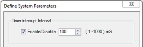
When enabled, the timer interrupt routine is executed based upon the interval selected (range is 1-1000 milliseconds).
All other operations are suspended whenever the time interrupt activates. Use this feature if you have a continuous operation that is time critical. Note that since timer interrupt routines halt all other activities, it is best to minimize its impact on the performance of the controller by using it sparingly. Design the interrupt routine to be as short as possible and adjust the timer interrupt interval to be the maximum setting that can still meet the requirements of your application.
User Defined Function Block (UDFB)
A User Defined Function Block (UDFB) operates similarly to a subroutine. It is a logic procedure defined by the user that can be executed as a component in another block. Once defined, the UDFB will be available to select from the list of instructions in the lower left of the editor window. The UDFB also allows the user to define input and output parameters making the block easy to reuse throughout the project. The Quick Start section below provides an example of how to create and use UDFBs.
Function Block Instances
One of the major advantages of the IEC61131-3 editor is the ability to modularize and reuse functionality through the use of Function Blocks. Once the logic in a Function Block is defined it can be used to create Function Block Instances. A Function Block Instance contains all of the logic defined in the Function Block as well as its own set of data to operate on. The Function Block can be thought of as a cookie cutter and the Function Block Instance is the cookie that the cutter creates. Multiple instances of the same block can be defined and each will have its own set of data to work with. The same block can be used for multiple purposes. Function Block Instances can be passed as parameters to other Function Blocks. Instances can be defined using the built in Function Blocks or User Defined Function Blocks.
The Function Block Instance folder, in the Project Information Window, is used to create Function Block Instances and contains a list of all the instances in the project. For details on how to create and use Function Block Instances refer to the Quick Start section below.
Tags
All of the logic in the various logic blocks operates on tags. Tags are linked to Graphic Objects displayed on the HMC, where the operator can interact with them using the touchscreen, or to the HMC’s IO modules, or some other IO mechanism. Tags are defined and listed in the tag database which can be opened by clicking the Tags folder of the project tree:
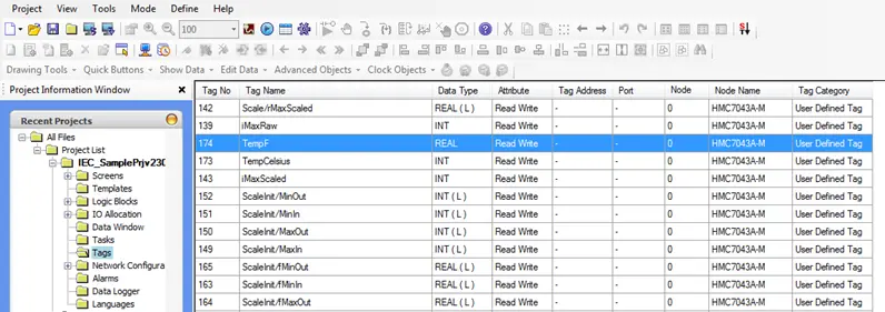
Tags are handled somewhat differently in IEC 61131-3 projects vs. Native Ladder projects. In IEC mode projects tags are not assigned an explicit address. Instead they are given name and a type, MAPware-7000 is responsible for allocating and tracking a memory address for the tag. For more information on creating and using tags refer to the MAPware-7000 programming manual. The following table lists the data types available in IEC 61131-3 programming mode:
| Data Type | Description | Bits | Value Range |
|---|---|---|---|
| BOOL | Boolean value can have one of two values: 1 (ON/True) or 0 (OFF/False) | 1 | 0 to 1 |
| BYTE | Unsigned Short (same as USINT) | 8 | 0 to 255 |
| DINT | Signed Double Integer | 32 | -2,147,483,648 to 2,147,483,647 |
| DWORD | Unsigned Double Integer (same as UDINT) | 32 | 0 to 4,294,967,295 |
| INT | Signed Integer | 16 | -32,768 to 32,767 |
| REAL | IEEE 754 format, single precision floating point number | 32 | N/A |
| SINT | Signed Short Integer | 8 | -128 to 127 |
| STRING | Variable Length string of ASCII characters | 1 to 255 bytes | N/A |
| TIME | Time of Day | 32 | N/A |
| UDINT | Unsigned Double Integer (same as DWORD) | 32 | 0 to 4,294,967,295 |
| UINT | Unsigned Integer | 16 | 0 to 65,535 |
| USINT | Unsigned Short Integer (Same as BYTE) | 8 | 0 to 255 |
| WORD | Unsigned Integer (Same as UINT) | 16 | 0 to 65,535 |
Tag Scope
Function Block and Function Block Instance Tags
In addition to global scope tags, tags can be associated with a function block instance. Function blocks can have; Input, Output and Internal tags. When an instance of the Function Block is added to the project it will have a copy of each of the tags. Internal tags can be defined in the tag database by setting the Scope to Local and selecting the Function Block to associate the tag with:
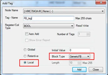
Input and Output tags are defined by right-clicking the UDFB’s folder in the project tree and selecting the Edit Parameters option. Once defined, Function Block Tags will appear in the tag database as <Function Block Name>\<Tag Name>. For example GenericFB\FB_tag is a tag internal to the GenericFB function block named FB_tag.
Arrays
In the MAPware-7000 tag database you can declare an array of a single type of tag. Arrays can have up to three dimensions and each dimension can have up to 255 elements. Arrays provide a powerful way to store and index into data at runtime. Arrays can be used for applications such as; look up tables, recipe storage, FIFO stacks, indirect addressing, or anything that requires an index into a data set.
Note: Arrays can only be indexed in the logic section of the project. To view data from an array on a screen, copy the data from the array to another tag in a logic block, or use the individual element tags created in the tag database. When the array is created the tag database will add individual tags for each element in the array. These tags can then be referenced on HMI screens.
Declaring Arrays
Arrays are declared in the tag database. To declare an array, right-click in the tag database and open the Add Tag window, specify a tag name and type for the array. Enter the size for each dimension in the Dimension field:
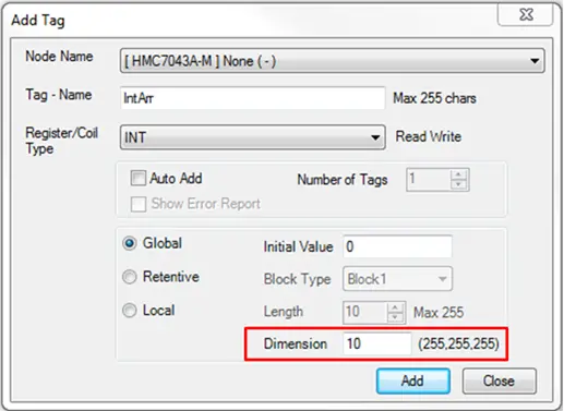
If a multi-dimensional array is required, enter the size for each dimension separated by a comma. The highest order dimension is listed on the left. For example:
- Enter: 8 for a one dimensional, 8 element array
- Enter: 6, 8 for a two dimensional array consisting of six one dimensional, 8 element arrays
- Enter: 4, 6, 8 for a three dimensional array consisting of four 6 x 8 two dimensional arrays
Click Add to allocate the array. In the tag database a tag is created for the array itself and for each element in the array. Indices for the individual element tags are specified by the numbers at the end of the tag name. Array elements are enumerated beginning at zero. An 8 element array will have elements 0 through 7.
Using Arrays
To use an array in a logic block, type the name of the array in any field where a tag of the array type can be used. The index of the array is enclosed in square brackets. If there are multiple dimensions, separate the index for each dimension with a comma. The index can be a tag or a literal value. For example, a three dimensional array named Arr could indexed with literal values as:
Arr[2,3,1]
Or, using the tags Index1, Index2, Index3 the array can be configured as:
Arr[Index1, Index2, Index3]
As the value of Index1, Index2 and Index3 change over time, the expression will point at a different array element.
Exporting and Importing Logic Blocks
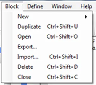
Logic blocks can be exported for use in other projects. Logic blocks are imported and exported using the Block menu. This menu only appears when a logic block is open in the editor window:
Export
To export a logic block, navigate to the block in the Project Information Window, and click the block’s folder to open the block for editing. The block can be a normal logic block or a UDFB.
From the Block menu select Export.
A windows dialog block will appear, allowing you to navigate to name the exported block and select a folder in which to save the block. The exported block consists of two files: an *.xml file which contains the logic used by the block, and a *.txt file which specifies meta data about the block, such as the version used to create it, the inputs and outputs etc. Both files are required to store the logic block for later import.
Import
To import a logic block, navigate to and open any block in the Project Information Window to enable the Block menu. Select Block > Import. Alternatively, enter <Ctrl>+<Shift>+I from anywhere in the project to open the import block dialog. In the dialog that opens, navigate to the *.xml file that contains the logic for the block to be imported.
Note: the folder containing the *.xml file must also contain the *.txt file for the logic block.
Once the block is imported it will appear under the project folder and will be available to use like any other user created block.
Connecting to External Devices
Details for using a particular driver can be found in the Controller Information Sheet for the device you want to use. Controller Information Sheets are available on the Maple Systems website. Overall, the HMC units only support Modbus and raw ASCII communications.
This section provides some general information about connecting external devices to an HMC unit in IEC-61131-3 programming mode.
Ethernet Settings (HMC2000)
To communicate using the Ethernet port, the Ethernet settings of the HMC must be configured with an address accessible to the external device. On an HMC2000 The unit’s IP address is configured on the Ethernet tab of the Project Configuration window (Project > Properties):
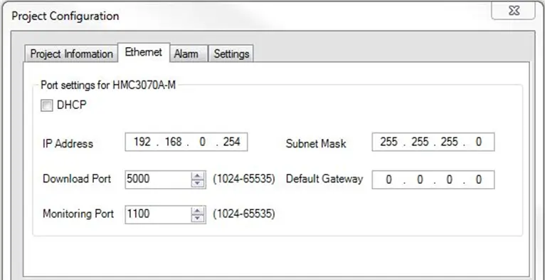
The IP address configured in this window must be accessible from the device to be connected to. Generally this means it must be on the same subnet, which boils down to:
- The portion of the IP address masked by the subnet mask must be the same for all devices on the subnet.
- The portion of the IP address not masked by the subnet mask must be unique for each device on the subnet.
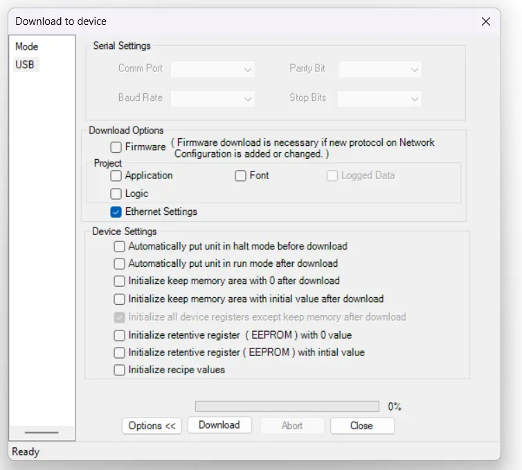
Once the IP address is set, it must be downloaded to the hardware. There is a checkbox in the download window for Ethernet settings. Don’t forget to check this box if the IP address needs to be updated:
Ethernet Settings (HMC4000)
Setting the Ethernet settings on the HMC4000s is a bit simpler, and is performed on the device itself.
You’ll start by pressing and holding the top-left corner of the device touchscreen until the unit opens the system settings.
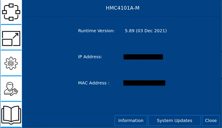
Right away, you’ll be able to see the IP address your HMC is set to, but if you press the connection icon in the top left, that will take you to the networking menu:
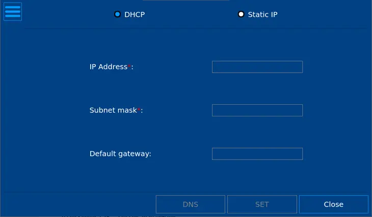
From here, you’ll be able to enter a static IP address (or set the unit to DHCP). Once you’re finished entering an IP address, click “SET” at the bottom of the screen, and the HMC’s IP address will be set.
Device Settings
To communicate to an external device such as an HMI or PLC, the communications driver for the device must be configured on the HMC port that the device is connected to. To add a device to the project, expand the Network Configuration folder in the Project Information Window, right-click the Com port to be used, and then select Add from the context menu.
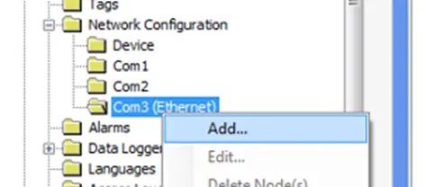
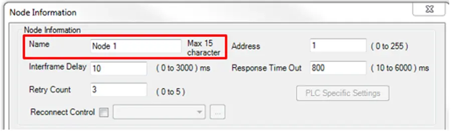
This will open the Node Information window, where you can configure the settings for your device. Detailed information for each communications protocol is available in the Controller Information Sheet for the device you are using. These can be found in the support center at www.maplesystems.com/support.htm.
The Node Name configured in this window will be selectable in the tag database in order to create tags addressed to this device:
Creating and Addressing External Tags
HMC as Client (Master)
Once the device is configured it will be available to select as a Node Name in the Add Tag window. Click the Tags folder in the Project Information Window to open the Tag Database. Right-click in the tag list and select Add to open the Add Tag window. Select the node in the Node Name dropdown list, then enter the name and corresponding address on the device:
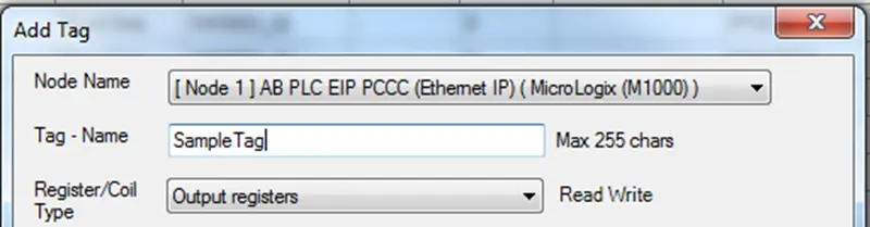
Once created, a tag can be used on HMC screens like any other tag. However, tags created on external nodes are not available to use in logic blocks. To use the tag in a logic block, it must be copied from the PLC to the local HMC onboard memory. This can be done with a task as shown below.
To copy data from an external device to internal tags
Configure a task to continuously copy data to/from and external device:
- Click the Tasks folder in the Project Information Tree to open the Tasks window.
- Select the radio button for the Global Tasks section
- From the select task dropdown list, select the:
- Copy HMI Block to HMI/PLC Block to copy data from the external device to the unit.
- Copy HMI/PLC Block to HMI Block to copy data from the unit to an external device.
- Configure the source and destination tags. Tag A is the destination and Tab B is the source.
- Enter the number of words to copy.
- Click Add to add the newly configured task to the Global Tasks box.
HMC as Modbus Server (Slave)
An external device can be configured to initiate read and write Modbus commands to the HMC which will respond as a slave. If the HMC is connected to the Modbus Master via Ethernet, there is no need to select a Modbus TCP/IP (Slave) driver in the Network Configuration Window. The HMC supports this driver on the Ethernet port by default. The HMC will respond to a properly formatted Modbus TCP request sent to the IP address (TCP port 502) configured in the Ethernet Settings tab in Project > Properties.
If the HMC is connected to the Modbus Master via serial com port, you must assign the Modbus RTU (Unit as Slave) driver to one of the available serial Com ports in the Network Configuration folder.
Next, you must map tags that are created in the Tag Editor to Modbus addresses. Any tags of the HMC that are mapped to Modbus addresses can then be accessed by the external Modbus Master device. For example, we wish to map the tags listed below to Modbus addresses:

Note that the Ethernet column is available by default. This column is used to specify Modbus TCP/IP (Slave) addresses for tags. To see the Com 1 column, you must add the Modbus RTU (Unit as Slave) driver in the Network Configuration folder.
To map a tag to a Modbus Slave driver address, simply enter the desired address in the column corresponding to that Com/Ethernet port being used. Note: click once anywhere on the row of the target tag to highlight (blue), then click the Com or Ethernet cell.
IEC61131-3 Quick Start Sample Project and Online Monitoring
Click the link above to learn how to create a quick start sample project using IEC 61131-3. This page guides you through the steps needed to create and run a simple IEC 61131-3 project. It will use a common engineering task, mapping a value from one scale to another, to demonstrate how the features of the IEC editor can be used to develop solutions. The sample project demonstrates:
- Passing an instance of a Function Block as a parameter to another Function Block
- Use of the Structured Text (ST), Ladder Diagram (LD) and Function Block Diagram (FBD) editors
- How to define a User Defined Function Block (UDFB)
- The difference between a Function Block and a Function Block Instance