
External Data Logger
External Data Logging Configuration
The HMC units have the option to log data to an external micro SDHC card. 4-32GB Capacity, supported speeds include Classes 2, 4, 6, 10, and UHS Class 1. Data can also be periodically sent to an ftp server through the Ethernet port.
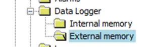
To configure an external Data Logger click the External memory folder in the Data Logger folder of the Project Information Window.
This will display the external data logger configuration window.
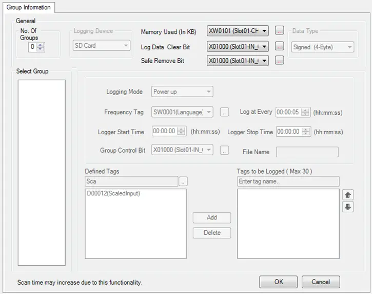
Configuring an external data log is essentially the same as configuring an internal data log. The differences are:
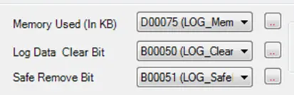
- There are three required tags used for the external data logger:
- Memory Used (In KB) (32-bit Unsigned Integer) displays the size of the data log files on the SD card in kilobytes. This is the total size for all groups.
- Log Data Clear Bit (Boolean) – Set on to erase the data log. Erases log files for all groups.
- Safe Remove Bit (Boolean) – It is safe to remove the SD card when this bit is off. Indicates that the logger is not actively writing to the SD card.
- Up to 50 groups can be configured in an external data log.
- File Name – this field is required to specify the name of the *.csv file for each group:

- The maximum sample rate is five seconds:

Configure the data log using the instructions detailed above. Once at least one Group is configured the FTP option will be enabled.
Reading Data from the SD Card
The external data log is not uploaded using the upload option (Project > Tools > Upload) in MAPware. To view the data, you must remove the SD Card and load it into a PC. The SD card contains two folders; FTP, and LOG.
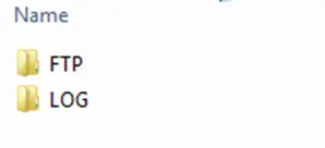
The FTP folder contains a list of files that were sent to the ftp server for each group. The LOG folder contains the *.csv files with data log data for each group. The file name corresponds to the File Name configured for the group, as shown in the previous section.
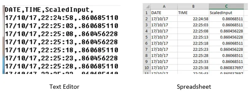
Simply open the file using a text editor or spreadsheet application capable of displaying csv data. The format of the data is a date and time stamp column followed by a column for each tag in the group. The Date stamp is in dd/mm/yy format. The time stamp is in hh:mm:ss format. The first line of the file is a header that specify the column as the date, time or tag name being logged.
Configuring the FTP Client
To configure the FTP client click the FTP folder in the Project Information Window:
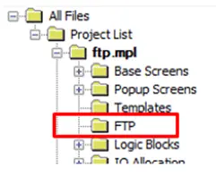
When at least one Group is configured in the external data log, the Configure FTP Client option is enabled. The HMC4000 does not require an external data log in order to use this feature, as long as an internal data log is configured. Check this box to enable the fields below:
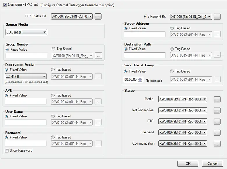
Configuration Settings
The fields in this window function as follows:
- FTP Enable Bit: When the bit is ON files will be sent to the ftp server. When OFF, nothing will be sent.
- File Resend Bit: When the bit is ON files are resent in the event that the server address or credentials are changed.
- Group Number: This corresponds to the group configured in the data logger.
- Source Media: This is the device that contains the data log that will be sent to the FTP server. Currently the only option is SC Card.
- Destination Media: This is the port on which the file is to be sent. Select Ethernet (3). Serial com ports are not supported at this time.
- APN: Is Access Point Name and is only required when using a com port as the destination media. This field is not applicable to Ethernet connection.
- User Name: This is the user name used to log into the ftp server
- Password: Password used to log into the ftp server
- Server Address: The IPv4 address of the ftp server
- Destination Path: Path to the folder on the ftp server where the data log is to be saved.
- Send at Every: Interval at which data will be sent to the ftp server. The HMC will create a new log file every time it writes to the ftp server. Each file contains only the data for the current interval. The date and time for the interval is appended to the file name that is written to the server. See using the ftp feature section below from details.
Status Registers
The ftp feature provides the status registers detailed below to aid in trouble shooting any issues logging data to the ftp server. All status registers are 16-bit unsigned integers.
- Media: This status register contains error codes for issues related to connection with the SD Card where the data is saved.
| Code | Meaning |
|---|---|
| 0 | No Error |
| 1 | Data Log in Progress |
| 2 | Media OK |
| 41 | SD Card Not Connected |
| 42 | USB Not Connected |
| 43 | File Systems Not Mounted |
| 44 | FTP Status File Does Not Exist |
| 45 | Upload File Does Not Exist |
| 46 | Unable to Open File |
| 47 | FTP Driver Not Defined |
| 48 | FTP Destination Media Not Supported |
| 49 | Source Media Not Supported |
- Net Connection: This status register contains error codes associated with network connection issues.
| Code | Meaning |
|---|---|
| 0 | No Error |
| 1 | Connecting to Network |
| 2 | Connected to Network |
| ls | Net Connect Error |
| 56 | APN Error |
- FTP: This status register contains error codes associated with connection to the ftp server.
| Code | Meaning |
|---|---|
| 0 | No Error |
| 1 | Authentication in Progress |
| 2 | Authentication Complete |
| 59 | User Name Length Error |
| 60 | Password Length Error |
| 61 | Server Length Error |
| 62 | Group Number Error |
| 63 | Connection Error |
| 64 | Timeout Error |
| 65 | Server Error |
| 66 | Operation Not Allowed |
| 71 | User Name Error |
| 72 | User or Password Error |
| 77 | Operation Error |
| 78 | Upload Error |
| 79 | Error Creating File |
| 80 | Unknown FTP Error |
- FTP Send: This register indicates the progress in sending the log file to the ftp server. Progress is indicated as a percent of total file size; i.e., a number from 0 to 100.
- Communication: This status register contains errors related to connection status.
| Code | Meaning |
|---|---|
| 0 | No Error |
| 1 | FTP Busy |
| 2 | Healthy Communication |
| 81 | Communication Lost |
| 82 | Communication Error |
Using the FTP Client feature
To use the ftp feature there must be an ftp server accessible at the configured IP address. The ftp server must be configured with the user and password specified and must permit write access for that user. The SD card must be present and contain a log file to send.
Provided the above conditions are met, the HMC will periodically upload a *.csv file to the ftp server. A new file is created each time the HMC transmits data logger data to the ftp server. Each file will contain only the data recorded since the last file was sent.
The name of each *.csv file consists of the file name specified for the group number, appended with the date and time information for when the file was sent. The period contained in each log file is determined by the Send File at Every field in the FTP Client Configuration window.
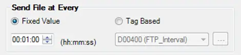
For example, consider an external data logger group (Data Logger > External memory) configured with:
- File Name set to logfile
- Logging Mode set to Power Up
- Log at Every set to 5 seconds
- Logging a tag called ScaledInput
- While the FTP Client is configured with Send File at Every set to 1 minute:
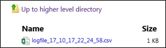
If the FTP client began sending files at 10:25:58 PM on October 17, 2017 the first file would be named: logfile_17_10_17_22_24_58.csv
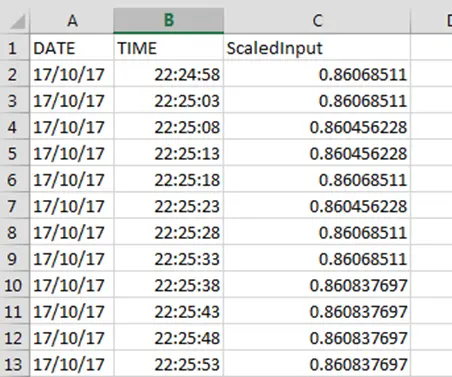
This file will contain 12 data samples, one taken every five seconds, between 22:24:58 and 22:25:58.
After 10 minutes there will be ten *.csv files:
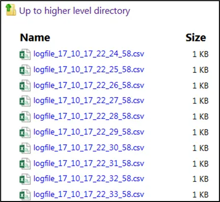
Each one containing 12 data samples.
FTP Host (HMC4000 Series)
The HMC4000 Series models can be configured as an FTP Host or server. The FTP host function allows files such as data log files stored on a USB or SD card on the HMC to be accessed from a PC on the local network or the internet.
All Ethernet-capable HMC4000 series models support the FTP Host feature.
How to Configure FTP Host
Follow the steps below for a guide on how to configure the FTP host feature for the HMC4000 Series models.
Instructions: How to Configure FTP Host
Find FTP Host Folder
Find the “FTP Host” folder in the Project Information Window.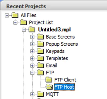
Open FTP Window
Click to open the FTP Host configuration window: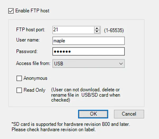
Check the “Enable” box
Check “Enable FTP Host” to enable the server.
The FTP host port can be set, and a username and password can be set to restrict access. Users can also be allowed to access the server anonymously.
FTP Host Port
The port should be left default (21), unless you have changed the ports used for an FTP connection in your PC.
User Name
The user name must be alphanumeric, no special characters and 50 characters max.
Password
The password must be alphanumeric, no special characters and up to 6 characters are allowed.
Access File From
USB by default. SD card is only supported on hardware revision B00 and later, check the label for the hardware revision.
Anonymous
If this checkbox is selected then no need for any account password validation when attempting to log into the server.
Read Only
If read only is checked,
Users cannot add content to the directory.
Users can upload files from the server to their PC.
Users cannot download files from the PC to the FTP server.
Users cannot delete files.
Users cannot change the file names.
Click OK
Click the OK button to finalize the configuration
Accessing the FTP Host
The FTP server hosted on the HMC4000 can be accessed from a PC that shares a network connection with the HMC using software such as WinSCP or even Windows File Explorer.
On a Windows PC that shares a network connection with the HMC4000, open File Explorer and enter the HMC IP “ftp://” followed by the IP address of the HMC. For example, ftp://192.168.0.254.
If a username and password has been configured for the server, a prompt will appear asking for credentials:
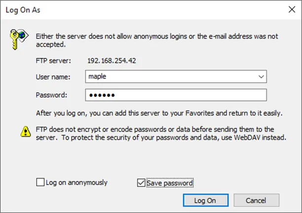
Once server access has been granted, any content residing on the USB drive connected to the HMC will be visible.
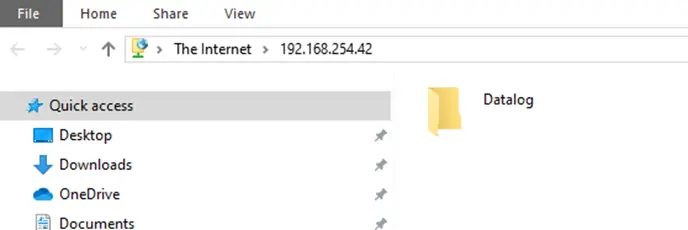
View Data on the FTP Host
If an internal datalog has been configured, the records will not be automatically available on the FTP host, since they reside in internal HMC memory and not on the external memory drive. (An external data log logs directly to external memory.) In this case, a task button can be used to copy the data records to the USB drive.
Select a task button from Advanced Objects > Single State Multi Task Button and place on screen.
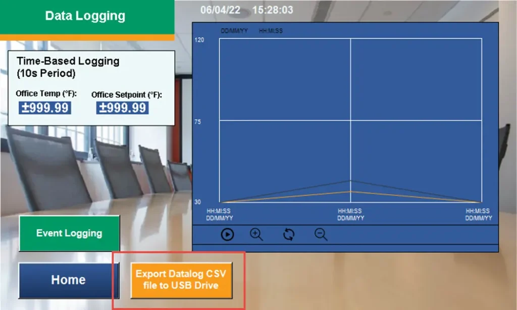
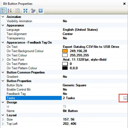
In the button properties, open the Tasks menu
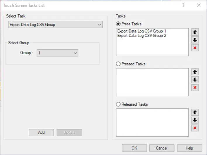
Select the task “Export Data Log to CSV Group” to export the data log file as a csv to the USB drive.
Other Data Logger tools
The MAPware configuration software provides some additional features for Data Logging that make this feature easier to use.
Reserved Memory in Tag Database for Data Logging
There are a number of system bits and registers in the tag database reserved specifically for Data Logger functions. Some of these have already been described in the sections above but here is the complete list:
| Register/Coil | Tag Name | Bytes | R/W | Recommended Object |
| S00012 | Refresh Historical Trend | Bit | Read/Write | Set Bit |
| Description: | Use this bit to update or ‘refresh’ the historical trend graph (HMC2000 only). Note: the historical trend graph is only updated when you initially call up the screen with the graph. Therefore, use this bit to refresh the graph without changing screens. | |||
| S00028 thru S00031 | DataLog Group # Log Control | Bit | Read/Write | Toggle Bit |
| Description: | Use these bits to Start/Stop data logging for the specified group when using Logging Mode: Bit Task. 0= Stop Logging, 1= Start Logging | |||
| S00037 | USB Host Menu Trigger | Bit | Read/Write | Set Bit |
| Description: | Use this bit to display a menu that allows you to download the Data Log file to a USB Flash Drive (HMC2000 only). | |||
| SW0002 | Logger Memory % Usage | 16-bit Register | Read Only | Numeric Display |
| Description: | This register shows a percentage of the allocated Data Log memory that has already been used by the Data Logger. | |||
| SW0003_00 | Logger Memory Full Status | Bit 0 of 16-bit Register | Read Only | Bit Lamp |
| Description: | This bit indicates when the Data Logger memory is full and has stopped logging. Note: this bit can also be tagged to an alarm message using the Alarm feature. | |||
| SW0003_01 | Logger Memory Clear Status | Bit 1 of 16-bit Register | Read Only | Bit Lamp |
| Description: | This bit indicates when the HMC is clearing the Data Logger memory. When this bit is 1, clearing memory is in process. When this bit is 0, process is completed. | |||
Tasks related to Data Logging
There are a number of tasks that are specifically used for Data Logging. Some of these have already been described in the sections above but here is the complete list:
| Task Name | Where Available | Parameters |
| USB Data Log Upload (HMC2000 only) | Power-On Tasks Global Tasks Screen Tasks- Before Showing Screen While Showing Screen After Hiding Screen Key Tasks (Global or Screen-Dependent) And Multi-Task Buttons Press task Pressed task Released task | DateTime: 12 consecutive registers used for the Start/Stop Date/Time values Group: 1 register for recording the Group #. Filename: 4 consecutive registers used to create filename used in USB Flash Drive. Status Register: 1 register to provide status of download. |
| Description: | This task is used to download a Data Log file to an attached USB Flash Drive. | |
| Key’s Specific Task: Refresh All Trends | Key Tasks (Global or Screen-Dependent) And Multi-Task Buttons Press task Released task | NA |
| Description: | This task is used to refresh the Historical Trend. | |
| Key’s Specific Task: Start/Stop Logger for All Groups | Key Tasks (Global or Screen-Dependent) And Multi-Task Buttons Press task Released task | NA |
| Description: | Use this task to begin or stop logging data for all data groups configured as Logging Mode: Key Task in the Data Logger | |
| Key’s Specific Task: Start/Stop Logger of Group # | Key Tasks (Global or Screen-Dependent) And Multi-Task Buttons Press task Released task | # = 1-4 |
| Description: | Use this task to begin or stop logging data for a specific data group configured as Logging Mode: Key Task in the Data Logger | |
| Key’s Specific Task: Clear Log Memory | Key Tasks (Global or Screen-Dependent) And Multi-Task Buttons Press task Released task | NA |
| Description: | Use this task to clear all internal memory of the HMC which is allocated for the Data Logger. | |
| Key’s Specific Task: Start/Stop Printing of Group A with Port B | Key Tasks (Global or Screen-Dependent) And Multi-Task Buttons Press task Released task | A = 1-4 (data group) B = 1-2 (serial com port) |
| Description: | Use this task to begin or stop printing data for a specific data group to a connected serial printer | |