
Creating a Sample Project using IEC 61131-3
Introduction
This section guides you through the steps needed to create and run a simple IEC 61131-3 project. It will use a common engineering task, mapping a value from one scale to another, to demonstrate how the features of the IEC editor can be used to develop solutions. The sample project demonstrates:
- Use of the Structured Text (ST), Ladder Diagram (LD) and Function Block Diagram (FBD) editors
- How to define a User Defined Function Block (UDFB)
- The difference between a Function Block and a Function Block Instance
- Passing an instance of a Function Block as a parameter to another Function Block
Like the previous Native Ladder Sample Project, this sample project will map an input value linearly to produce an output value on a different scale, only this time, we will create the logic that does the scaling. We will scale values from Celsius to Fahrenheit and from a raw input value to an engineering value (i.e. from a 12 bit raw input to a voltage). The solution should be general enough so that the Function Blocks created can be re-used for any linear scaling operation. We also want the calculation to be as efficient as possible. The task of scaling a number can be broken down into two parts.
- Calculate the slope and offset
- For a given input calculate the output
We could do both of these operations in one function block, but that would mean that every time the value is scaled, the slope and offset are recalculated. Instead we will create two function blocks; one to calculate the slope and offset given maximum and minimum values, and one to actually do the scaling as the input changes.
Creating User Defined Function Blocks to accomplish the task eliminates the need for multiple logic blocks that do the same thing, making the project easier to maintain. Edits can be made in one place and take effect throughout the project.
Create a New Project
We will use the same HMC4070A-M that we used in the previous Native Ladder sample project. Once a project has been created in either Native Ladder or IEC 61131-3, it cannot be converted to use the other programming language, so we will create a new project for this example.
- To create the project, select Project > New. The Select Product window is displayed.
- Select the Product Series, Product, and Model.
- Leave the Display Orientation as Horizontal.
- Native Ladder is the default Programming Language and for this sample project must be changed. Click the drop down to select IEC61131-3.
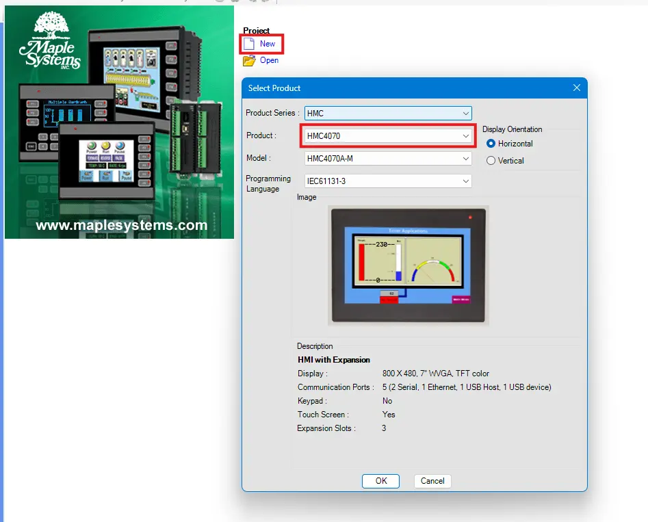
- Click OK. A new project is created with a default name.
- Select Project > Save to save the project with a unique name.
The Editor Window
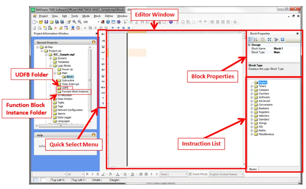
Let’s take a quick tour of some of the aspects of MAPware-7000 that are unique to an IEC 61131-3 project. Clicking the folder for Block1 in the Project Information Window displays the editor for that block. The default logic block uses the Ladder Diagram editor, so the Ladder Diagram editor is displayed when the Block1 folder is selected.
- Block Properties – This area displays the execution type and name of the logic block.
- Instruction List – Lists all the available instructions for the project. Instructions are categorized according to functionality. Expand the node for a given category to see individual instructions. To add a particular instruction, click and drag it into the editor window. Subroutines and UDFBs (Function Blocks that users create) will appear under the Project folder of the Instruction List once they are defined. Information on how to configure and use a given function block is available in the help file. To access the help file entry for any of the blocks in the Instruction List, simply double-click the instruction.
- Editor Window – This is where the logic is defined. It displays the graphical or text representation of the logic program.
- Quick Select Menu – The options available on this menu depend on the editor in use but provide quick access to common program elements. Click the location in the editor where you want to place the element then click the element in the quick select menu to place it in the editor.
- UDFB Folder – This folder contains the definitions for User Defined Function Blocks further described below. To add or edit a UDFB, click the block name in this folder. To use a UDFB in another logic block, select it in the Project folder of the Instruction List.
- Function Block Instance Folder – This folder contains a list of all the Function Block Instances in the project further described below. Each block can have multiple instances, and each instance will have its own private set of data to work with. Thus, one type of function block can be utilized for multiple purposes in the project.
IEC Specific Logic Blocks and Execution Style
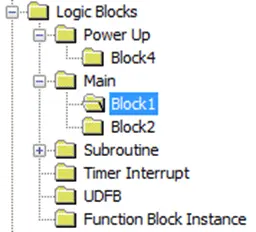
In addition to the Power Up, Main, Subroutine, and Timer Interrupt execution styles available in the Native Ladder Editor, the IEC programming mode also allows you to create User Defined Function Blocks and Function Block Instances.
The current Execution Style of a logic block is indicated by the block’s location within the Logic Blocks folder of the project tree.
Subroutines
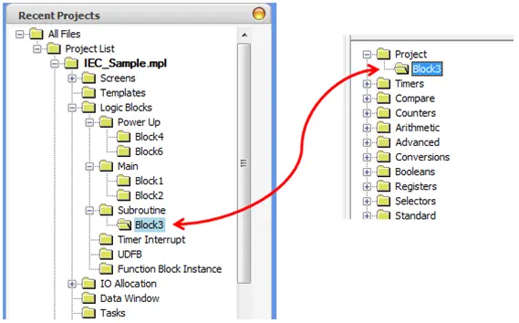
In IEC mode, when a block is created as a Subroutine block, it will appear in the Instruction List under the Project folder as a function block that can be used within logic blocks.
User Defined Function Block (UDFB)
A User Defined Function Block (UDFB) operates similarly to a subroutine. It is a logic procedure defined by the user that can be executed as a component in another block. The UDFB also allows the user to define input and output parameters, making the block easy to reuse throughout the project. Once defined, the UDFB is also available to select from the Instruction List under the Project folder. We will create two UDFBs in this sample project.
Function Block Instances
One of the major advantages of the IEC61131-3 editor is the ability to modularize and reuse functionality through the use of Function Blocks. Once the logic in a UDFB or Subroutine is defined, it can be used to create Function Block Instances.
A Function Block Instance contains all of the logic defined in the Function Block as well as its own set of data to operate on.
The Function Block can be thought of as a cookie cutter and the Function Block Instance is the cookie that the cutter creates.
Multiple instances of the same block can be defined and each will have its own set of data to work with. The same block can be used for multiple purposes.
Function Block Instances can be passed as parameters to other Function Blocks.
Instances can be defined using the built in Function Blocks or User Defined Function Blocks.
The Function Block Instance folder, in the Project Information Window, is used to create Function Block Instances and contains a list of all the instances in the project. We will create multiple Function Block Instances in our sample project.
Add Tags to the Project
Tags are handled somewhat differently in IEC 61131-3 projects vs. Native Ladder projects. In IEC mode projects, tags are not assigned explicit addresses. Instead they are given a name and a type, and MAPware-7000 is responsible for allocating and tracking a memory address for the tag.
Tag Scope
In addition to Global scope tags, tags can be associated with a Function Block Instance. UDFBs can have input, output, and internal tags. When an instance of the UDFB or built in function block is added to the project, it will have a copy of each of the tags. Internal tags can be defined from the Tag Database by setting the Scope to Local and the Block Type to the Function Block Instance the tag is associated with.
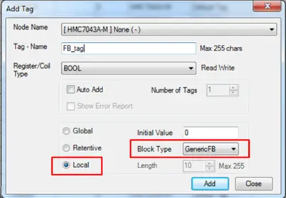
Input and output tags are defined by right-clicking the UDFB’s folder in the project tree and selecting the Edit Parameters option. Once defined, Function Block Tags will appear in the Tag Database as <Function Block Name><Tag Name>. For example, GenericFBFB_tag is a tag internal to the GenericFB function block named FB_tag.
For more information on creating and using tags, refer to the MAPware-7000 Programming Manual.
Open the Tag Database by clicking the Tags folder in the Project Information Window.
Use the Add Tag window to create the following tags.
- Temp1C – INT – Global – Simulated Temp input 1 [C]
- Temp2C – INT – Global – Simulated Temp input 2 [C]
- Temp1F – REAL – Global – Scaled Temp output 1 [F]
- Temp2F – REAL – Global – Scaled Temp output 2 [F]
- RawInput – INT – Global – Simulated IO card input
- Voltage – REAL – Global – Input scaled to a voltage value
Logic Blocks
Create a User Defined Function Block (UDFB)
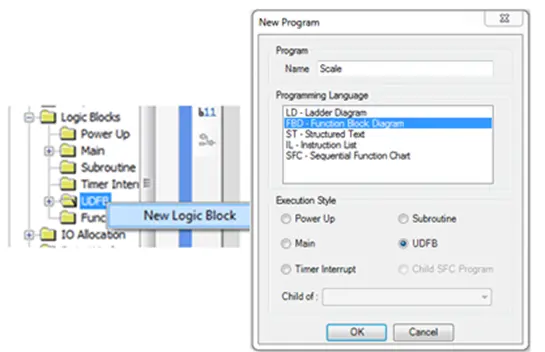
Next we want to create our own User Defined Function Block (UDFB). This block performs the scale operation. We will use the Function Block Diagram (FBD) editor to define this block.
- Expand the Logic Blocks folder in the Project Information Window
- Right-click the UDFB subfolder and select New Logic Block
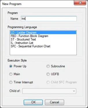
- In the New Program window name the function Scale and select FBD – Function Block Diagram as the Programming Language and UDFB as the Execution Style
- Click OK to create the Logic Block
- A new block called Scale appears in the UDFB folder of the Project Information Window, and a new instruction called Scale appears in the Project folder of the Instruction List.
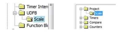
- Before creating the logic for this block we need to define the inputs and outputs so that other logic blocks can pass data to it. Right-click the Scale folder in the Project Information Window and select Edit Parameters.
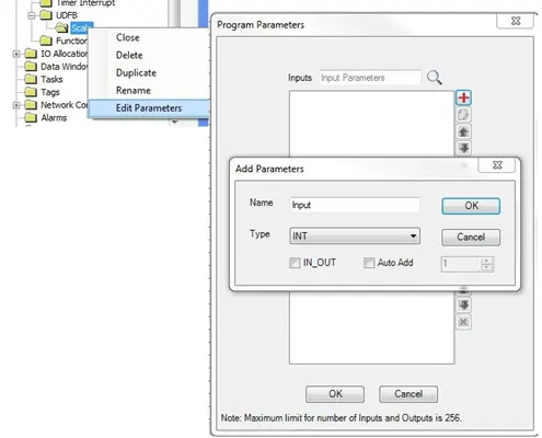
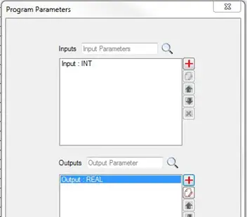
- In the Program Parameters window, click ‘Add Input Parameter’ under Inputs.
- The Add Parameters pop-up window allows you to specify a name and data type for a new input parameter. This block contains only one input parameter imaginatively named Input. Set the type to INT then click OK.
- Next click ‘Add Output Parameter’ under Outputs to create the output. It is named Output and has type REAL.
- Once complete, the Program Parameters window should appear as shown below. Click OK to create the Parameters.
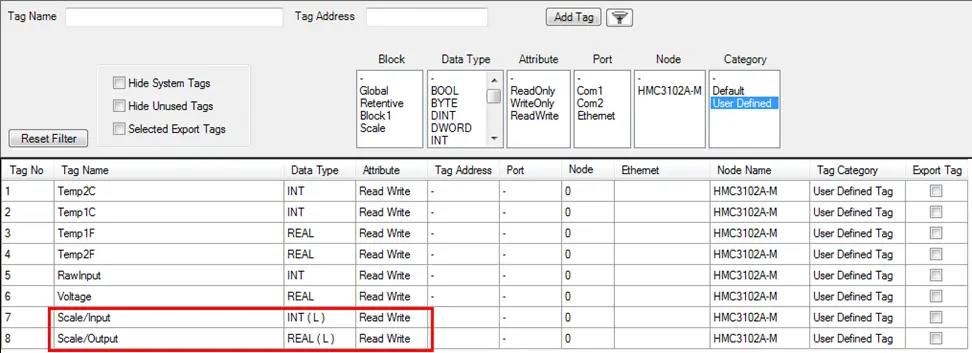
Both tags should now appear in the tag database with the Function Block/Local Tag format we talked about earlier.
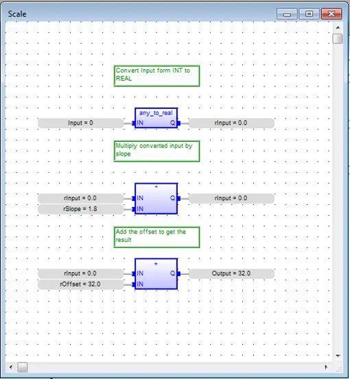
Logic can now be entered into the block to define its functionality. The first thing we want the Scale logic block to do is convert the input to floating point (real) format.
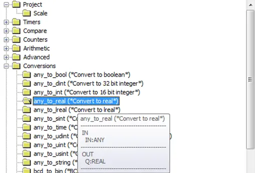
- In the Instruction List at the bottom right of the editor window, expand the Conversions folder and locate the any_to_real instruction. Click the instruction and drag it into the editor window.
- The input to this instruction will be the UDFB’s Input parameter. Double-click the instruction’s input area and type Input into the pop up box.
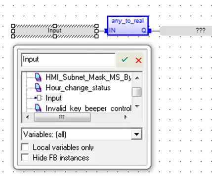
Note: Notice that because Input is an input parameter for this UDFB, it shows up in the context list with an input icon.
- For the output, we want to define a new tag that will be local to the Scale function block. Double-click the output area of the any_to_real instruction and type rInput into the pop up and hit enter.
- Because a tag with this name does not exist yet, MAPware-7000 will display a dialog box that can be used to define the tag.
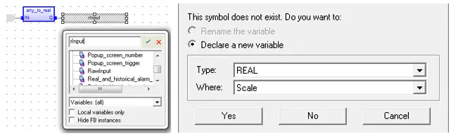
Set the type to REAL and Where to Scale. This sets the scope of the variable to the Scale function block.
- Click Yes to create the new variable.
- Now that the input is in the correct format, all we have to do is multiply by the slope and add the offset. Expand the Arithmetic folder in the Instruction List and drag a * (Multiply) instruction to the editor window.
- The first input here will be the rInput tag created in the last step. Double-click in the first input and type rInput into the pop up window. Notice that rInput is now in the list as a local variable.
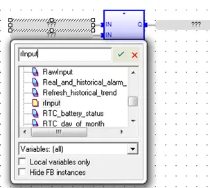
- The second input will be a local variable called rSlope. This tag doesn’t exist yet, so click the second input and type rSlope to create the new tag.
- Set Type to REAL and Where to Scale using the context window as described above.
- We will write the result of the multiplication back to the rInput variable. Select rInput for the output (Q) of the instruction.
- The last step is to add the offset. Drag an + (Addition) instruction from the Instruction List into the editor window.

- The first input for this instruction will again be the rInput variable. Double-click the first input and select rInput from the tag list.
- The second input will be a new local variable called rOffset. Type rOffset in the box for the second input and create a new tag. Make sure the Type is REAL and Where is set to Scale.
- Finally, the output will be the previously created output parameter of the function block. Select Output from the menu for the output (Q) tag. Notice that it will have an output icon in the tag list.
- Here is what the Scale function block should look like when complete (some comments were added for clarity).
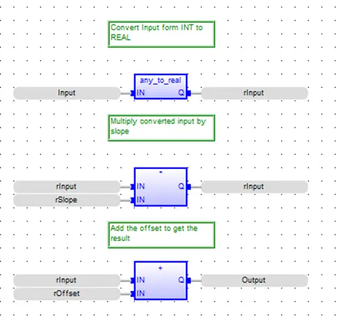
This is a good time to compile (Project > Compile) and save the project to make sure there are no errors before moving on.
Create a Second UDFB to Initialize Instances of the Scale Function Block
Before we can use the Scale function block, we have to initialize the offset and slope parameters. These are calculated from maximum and minimum values for the input value and the scaled value. We will create a new UDFB to do this calculation and initialize the function block instances. This new block will use the ST – Structured Text editor.
Structured Text is a text based programming language in which program instructions are entered as discrete statements in a text source file. This programming method is similar to other high level programming languages such as C or Visual Basic.
The basic unit of a structured text program is a statement. A statement is an instruction for the processor to perform some set of actions. Structured Text programs are simply lists of statements.
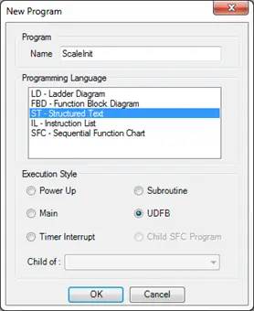
- Right-click the UDFB folder in the project information window and select New Logic Block.
- Name this block ScaleInit, and select ST – Structured Text for the Programming Language.
- Click OK to create the block.
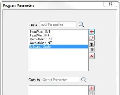
- Next, we will define the input parameters for the ScaleInit function block. Right-click the block’s folder in the Project Information Window and select Edit Parameters from the context menu to open the Program Parameters window.
- This block will have no outputs. Enter the following inputs.
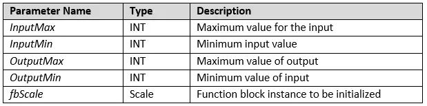
Note: The last parameter is of type Scale. This means that a Scale function block instance will be passed into the function block. The function block can then operate on the data specific to that function block instance. The input parameters should look something like this when finished.
Now we can start entering code for the ScaleInit function block. This block will contain several local variables to perform the calculation. In the Structured Text Editor, when enter is pressed at the end of a statement or line of code, the editor will validate all of the parameters in that line. If it finds parameters that don’t exist, a dialog box will pop up allowing new variables to be defined, just as in the Function Block Diagram editor. Below is a table of all the local variables to be defined.

Below is the code to be entered into the ScaleInit function block. The first four lines use the any_to_real function to convert our input tags into real numbers. Then next line calculates the slope from the given range, and places it into the internal rSlope variable of the fbScale function block instance. The last line calculates the offset and places it in the internal rOffset tag of fbScale.
// Convert inputs to floating point numbers
rInputMax := any_to_real (InputMax);
rInputMin := any_to_real (InputMin);
rOutputMax := any_to_real (OutputMax);
rOutputMin := any_to_real (OutputMin);

// Calculate slope
fbScale.rSlope := ( rOutputMax - rOutputMin ) / ( rInputMax - rInputMin );

// Calculate offset
fbScale.rOffset := rOutputMax - ( fbScale.rSlope * rInputMax);Code language: JavaScript (javascript)
Note: The lines beginning with “//” are comments and provide context, but are optional and have no effect on the code.
- Copy the first statement above, rInputMax := any_to_real (InputMax);, and paste it into the Structured Text Editor. Hit the Enter button on your keyboard.
- A popup window to define rInputMax appears. Set the Type to REAL and Where to ScaleInit. Click Yes.
- Copy the rest of the code into the Structured Text Editor one line/statement at a time, pressing Enter after each line to define the local tags. Each tag should be of type REAL and local to ScaleInit.
- After all the code has been entered, compile (Project > Compile) and save the project to verify that there are no errors, and fix any typos as needed.
Note: If you copy and paste the code in its entirety from here into the editor, tags will not be created for the internal variables because the code was not entered one statement at a time. You must manually enter each tag into the database in this case.
For more information on Structured Text commands and formatting, see the MAPware-7000 IEC 61131 Programming Guide.
Use the UDFBs in Ladder Diagram Blocks
Now that the function blocks have been created, they can be put to use in other parts of the project. We want to use the ScaleInit function block in a power up routine to initialize two Scale function block instances.
- Right-click the Power Up folder and select New Logic Block. This block will be called Init and will be a LD – Ladder Diagram block.
- Expand the Project node in the Instruction List. The Scale and ScaleInit function blocks should appear there.
- Click the ScaleInit instruction and drag it to the top rung of the Ladder Diagram.
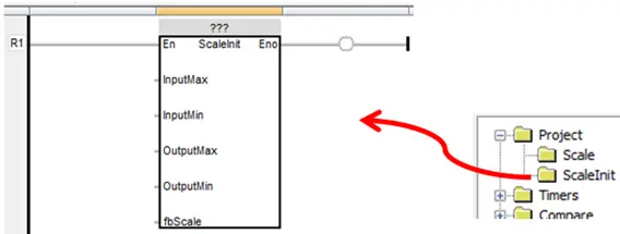
Notice the ‘???’ at the top of the block. This indicates the function block instance has not been selected.
- Double-click the question marks and enter fbScaleInit in the tag selection window. Click the Accept icon and declare the new variable as type ScaleInit and Global scope.
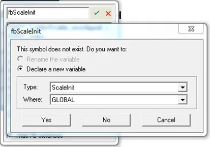
This defines a new instance of the ScaleInit Function Block called fbScaleInit. This instance will now be listed in the Function Block Instance folder in the Project Information Window along with the previously created fbScale instance of Scale defined earlier, local to ScaleInit.

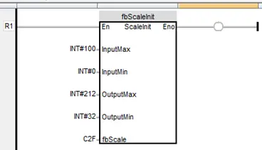
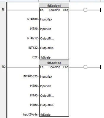
- Next we will specify the input parameters. For this sample, we will use literal number values for the maxes and minimums. Double click to the left of each of the first four inputs and type in the following values.

- The last parameter is the Scale function block instance to be initialized. In this case it will be a new instance called C2F (Celsius to Fahrenheit). Double-click the fbScale input and type C2F into the selection box.
- Set the Type to Scale and Where to GLOBAL in the popup window and click Yes to create the C2F instance.
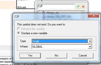
The C2F instance is created, added to the Function Block Instance Folder and selected as the fbScale input parameter.
This is what the instruction should look like now.
Next we want to initialize a different Scale function block instance called Input2Volts. This instance will be used to convert from a raw input to a voltage. The process is the same as above, but with a different function block instance as the input parameter and with different maximum and minimum values.
- We will use the same instance of the ScaleInit function block. Drag a new ScaleInit instruction to rung 2 from the Instruction List.
- Click the ‘???’ above the block and again enter fbScaleInit in the popup window. This time, the fbScaleInit instance will appear in the variable list since it was already defined.
- Enter the following values for the input parameters.
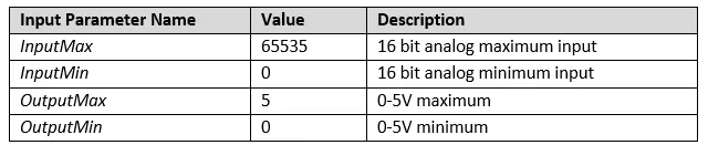
This sets up the Input2Volts function block to convert from a 16 bit input to a 0 to 5 V output.
- Enter Input2Volts for the fbScale input.
- The Input2Volts function block instance will need to be defined. Set the Type to Scale and Where to GLOBAL as before.
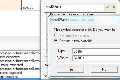
This will add a new Scale function block instance called Input2Volts to the Function Block Instance folder. Here is what the Init function block should look like when complete:
Define the Main Routine Block 1
The final piece of logic in the sample project uses C2F and Input2Volts instances to continuously convert our simulated inputs to the desired output values as the inputs change over time. We can use the ladder diagram block automatically created by MAPware-7000 to do this.
- Click the Block1 folder under Logic Blocks / Main in the Project Information Window to edit the block.
- Click and drag three Scale blocks from the Instruction List into the editor.
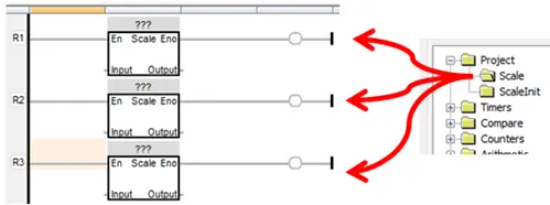
- Next click the ‘???’ in each block to specify the function block instance to be used. The first two will use C2F and the last one will use Input2Volts.
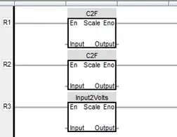
- Specify the input and output parameters for each instruction. We will use the tags created at the beginning of this section.
- Rung 1 converts Temp1C to Temp1F
- Rung 2 converts Temp2C to Temp2F
- Rung 3 converts RawInput to Voltage.
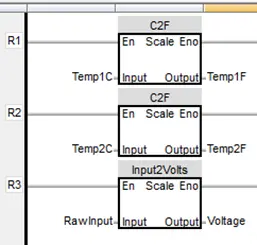
- That’s it for the logic. Check that the project compile (Project > Compile) and save the project to verify that there are no errors. Fix any typos as needed.
Create Screen Objects
We will create a very simple screen to control the inputs and observe how the outputs change. This section will not go into great detail on creating the objects needed, for they were covered in the previous Native Ladder section. The screen should eventually look something like this:
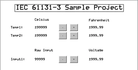
- Navigate to Screen1 under the Base Screens folder in the Project Information Window.
- Create the Text object labels shown above [Celsius, Fahrenheit, Raw Input, Voltage, Temp1:, Temp2:, and Input1:].
- Create three Numeric Entry objects (Draw > Input Objects > Data Entry > Numeric Entry), to display and write to the three inputs; Temp1C, Temp2C and RawInput.
- Change the Font for these objects to 10 x 14 to make them easier to read, and select the appropriate tag in the Tag Name property.
- For the Temp1C and Temp2C objects set the Data Type format to Signed [-32768 To 32767] to allow negative temperatures to be displayed correctly.
- Next we will use Multi-Task Single-state buttons (Draw > Buttons > Multi-Task Single-state) to create the increment and decrement buttons that control the input tags. Place a button next to the first Numeric Entry object.
- For the increment button, change the On Text property to “+”.
- Click the Tasks property, then on the button to configure a task for the button.
- Before selecting the task, click the Pressed Task radio button. This means that the value will increment while the button is pressed.
- Select the Add a Constant Value to Tag task from the Select Task list. Select Temp1C for the Tag and enter 1 for the Number to add.
- Click the Add button. The task should appear under Pressed Tasks.
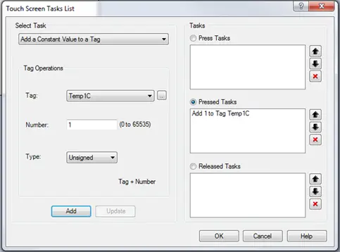
- Click OK to save the task.
- Make a copy of the increment button to use as the starting point for the decrement button.
- Change the On Text to “-“.
- Change the Task to a Subtract a Constant Value from Tag task that subtracts 1 form Temp1C.
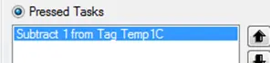
- Once you have increment and decrement buttons controlling Temp1C, make copies of them to control Temp2C and RawInput. You can update the task with the correct tag by clicking the task in the Pressed Tasks list. When changing the tag, make sure the number is re-entered, and don’t forget to click Update and OK to save the changes. For RawInput, you may want to change the add/subtract numbers to 10 or 100 so that the value changes faster.
- Finally add three Numeric Display objects to display Temp1F, Temp2F and Voltage. These are floating point numbers so, after you select the tag, change the Data Type property to Float [Max 9 digits].

- Compile and save the project one last time. It is ready to download and run on the HMC hardware.
Testing the Project
Download the project to the HMC4070A-M using the same procedure described before. Then use the increment and decrement buttons we created to change the inputs and verify that the outputs change to the correct scaled value.
Online Monitoring
Installing the Virtual Com Port driver
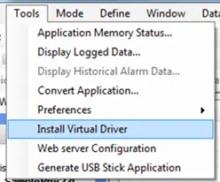
In IEC 61131-3 mode, MAPware-7000 requires an additional communication driver, the virtual com port driver, be installed before starting an Online Monitoring session using over USB. To install the driver go to Tools > Install Virtual Driver.
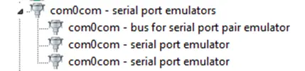
This driver will add several ports in the development PC’s Device Manager.
Going Online
With the drivers in place, the HMC can be monitored with MAPware-7000 while it is executing a program. Select the USB mode from Tools > Preferences > Online Communication Mode and then click the icon to go online.
Selecting Logic Blocks and Function Block Instances
Once the online session begins, any open logic blocks will have variables loaded with their real time values.
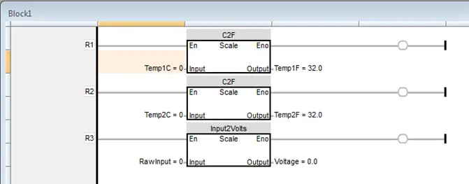
Logic blocks can be opened for monitoring by selecting them in the project tree.
When opening a Function Block that has multiple instances, MAPware-7000 needs to know which instance to open. Thus when a UDFB that has multiple instances is selected, a popup window will appear listing the available instances of that function block to monitor.
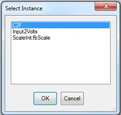
Once the selection is made the function block will be loaded with the real time data for the selected instance.
Manipulating Data
To change the value of a parameter simply double-click the parameter.
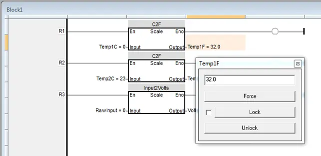
The popup window allows you to force and or Lock / Unlock the value of the parameter. When a parameter is forced it is written to once. If some other logic writes to the parameter after it is forced the forced value will be overwritten. If the value is locked, MAPware will prevent any other logic in the block from overwriting the forced value. Parameters that are locked will appear in double square brackets.

Note: The lock only prevents logic blocks from writing to the value. The value can still be changed by a task or by entering data in a numeric object on an HMI screen.
Review
Let’s review some important points about how this sample project is structured that will allow you to take full advantage of IEC 61131-3 features. Although not all of the features available in MAPware-7000 or the HMC Series have been covered, we have taken our first steps in using this software and becoming familiar with device operation.
First, notice how we used multiple instances of a User Defined Function Block. We are scaling three inputs, but have defined our scaling logic in only one place, the Scale UDFB. If something needs to be changed, it only needs to be changed in one place, and it isn’t necessary to hunt through the project to make sure the logic is updated everywhere it is used. We reused a single instance of the function block to scale two different inputs and used a separate instance to scale another input on a totally different scale. We could have many more channels and many more scales, but still only need one UDFB. If there was a radically different scaling operation that needed to be done, such as a lookup table, then we would need to create a different UDFB.
Next, note that three different editors were used, and it is possible to call the logic created in one editor from logic created in another. The different languages each have their own strengths. Ladder Diagram provides a clear graphical representation of the logic flow, Function Block Diagram is great for combining operations in a simple to read structure, and Structured Text can be used for more involved operations that might look quite complicated in one of the graphical editors. By combining logic from the different editors we are able to take advantage of the strengths of each.
Finally, note that we were able to separate the logic for initializing the scale block (UDFB-ScaleInt) and actually performing the scale operation (UDFB-Scale) into two separate operations. We did this by passing a UDFB instance as a parameter to another UDFB. This keeps the scaling operation, which occurs frequently while the project is running, as simple and quick as possible. Breaking complex operations into simple building blocks is another way to make a project more maintainable.