
Data Window
The Data Monitor feature is a window available in the MAPware software that displays data values in HMC internal memory. The entire internal memory of the HMC is accessible using the Data Monitor but you select what areas of memory you wish to monitor. In addition to reading values, you can modify data online or create a table of preset values to download to the registers. With this feature, you can quickly view data in table format or to initialize areas of memory in the HMC.
To access the Data Monitor window, click View > Data Monitor Window from the standard menu, or click the Data Monitor icon in the standard toolbar or click the Data Monitor folder in the Project Information Window:
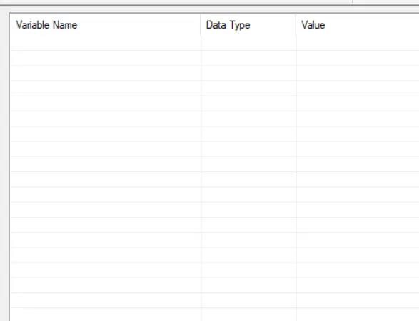
By default, the Window shows a blank grid with no tags being monitored. To add a tag to monitor, right click anywhere on the Data Window to display a popup dialog box:
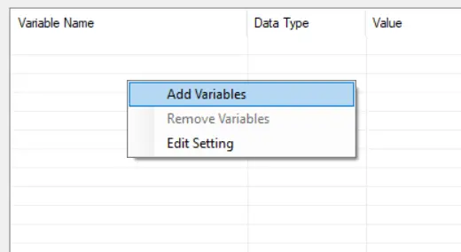
Add a Variable
By clicking the New Block option in the dialog box above, the typical tag selection window is displayed:
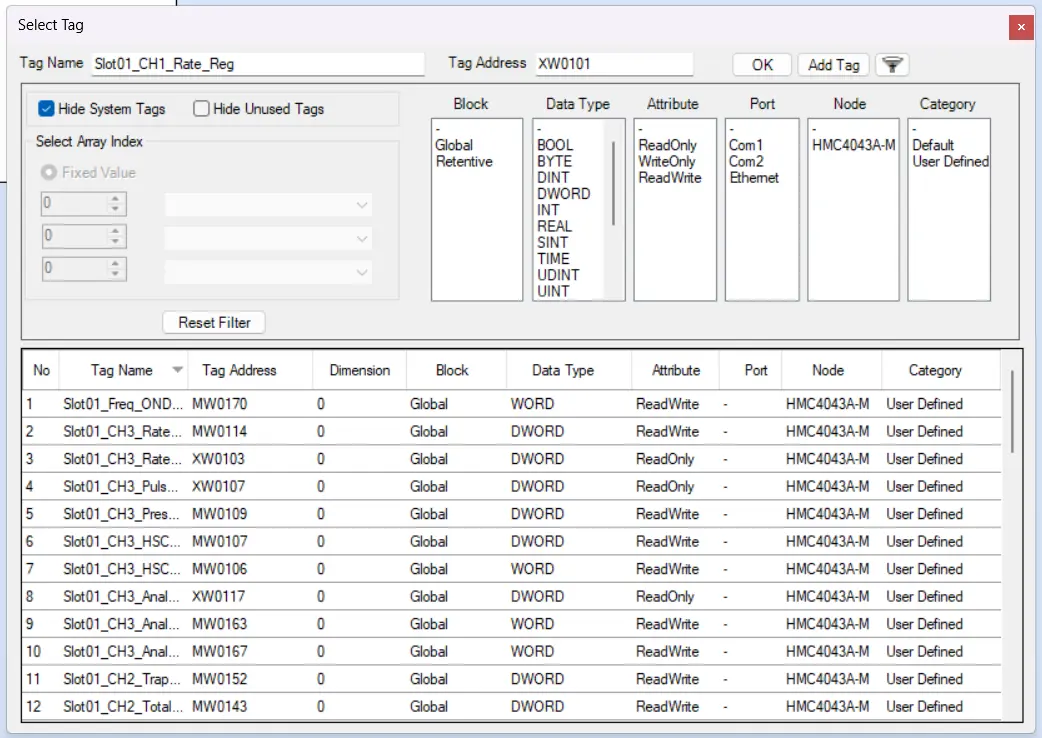
Once you select a tag or tags, click “OK” to go back to the Data Window.
Remove Variables
Select a tag, or multiple tags, right-click and select “Remove Variables”
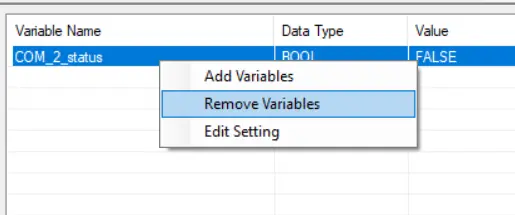
MAPware-7000 will then confirm if you want to remove the tag(s) you’ve selected from the Data Window.
Edit Setting
If you select “Edit Setting” in the right-click menu of the Remove Variables, this will be displayed:
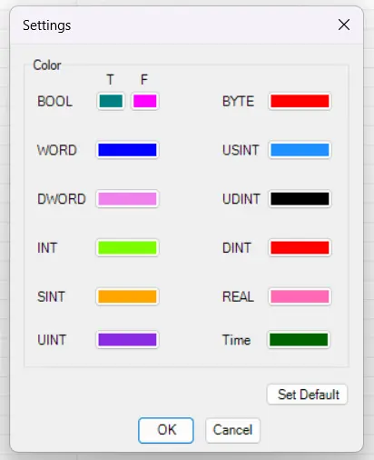
This allows you to change the colors that each tag type will be displayed as in the Data Window.
Monitoring Data using the Data Monitor
Once you have created your Data Monitor window and downloaded your preset values (this is an optional step), you are ready to monitor the HMC.
How to monitor the HMC
Follow the steps below to monitor the HMC.
Instructions: How to monitor the HMC
Start MAPware
Open the MAPware-7000 Software, and open the project that’s loaded on the HMC you’ll be monitoring.Connect the PC
Use an Ethernet or USB Cable to connect the PC to the HMC you wish to monitor.Go Online
From the Mode menu, select the “Go Online–> without Upload” optionYou can also click the “Go Online” icon in the standard toolbar.
Wait for HMC Data loading
MAPware displays a message stating that it is loading data from the HMC (this takes a few minutes). When finished, the MAPware software displays the main Logic block.
Display Data Window
Press F10 on your keyboard to display the Data WindowYou can also click the Data Window icon
Change Values
You can change values while online with the HMC simply by double-clicking a registerThe new value is sent to the HMC immediately after you press the Set button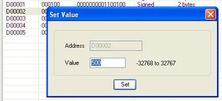
Disconnect when done
When you are finished using the Data Monitor mode, click the Go Online button again to go offline
Halt Mode
Halt mode is useful if you wish to change values in the Data Monitor window but not while the HMC is running the project you downloaded into it. However, the HMC will clear all internal memory registers (except the retentive memory) when you place the HMC in Run mode again.
To place the unit in Halt mode, click the Halt icon in the standard toolbar. To resume, click the Run icon.
Application Memory Status (HMC2000 only)
The Application Memory Status feature is a tool available in the MAPware software for HMC2000 models that is used to display memory used by the current project. This tool can be used to determine how much memory is still available for new screens, ladder logic, etc.:
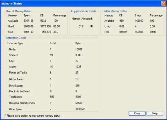
It also provides details on how the screen memory is currently allocated. The memory is divided into three main areas:
- Application Memory – this is the memory used for screens, global tasks, alarms, and tags.
- Data Logger Memory – indicates how much memory has been allocated for the data logger feature.
- Ladder Logic Memory – shows how much memory has been consumed for the ladder logic diagrams.
This tool is accessible is by clicking Tools > Application Memory Status from the menu bar.
Retentive Tags
For projects created in Native Ladder programming mode, the Keep Memory Area feature provides the ability to retain values in designated internal memory after removing power from the HMC. Click Define > System Parameters from the menu bar:
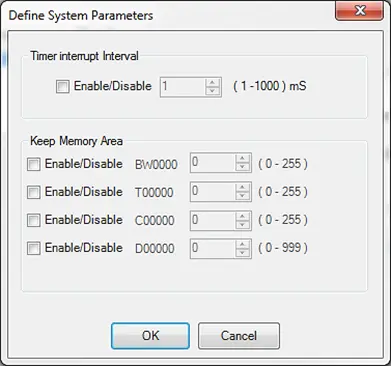
To enable, click the Enable/Disable checkbox next to the memory that you wish to use (BW, T, C, or D). Enter the number of registers (starting with 0) that you want as retentive memory. For BW, T and C registers up to 256 registers (0 to 255) can be used as keep memory. Up to 1000 D registers (0 to 999) can be used as keep memory. The total number of keep memory registers cannot exceed 1000.
To use these registers, you must initialize them in the Tag Database.
For MAPware Projects, if you want to retain tag values across power cycles, you’ll need to define those tags as “retentive”. While you’re adding a tag to the tag database, you can set the tag as retentive:
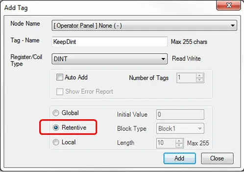
Once you create a tag with this option, it will save its value in non-volatile memory, and therefore retain that value when you power cycle the unit. A maximum of 2,000 bytes can be used to define Retentive tags (i.e., 500 DINTs, 1,000 INTS, 16,000 BOOLs etc., or some combination thereof). Tags created as Global can be changed to Retentive during project development and vice versa.
When you download your project into the HMC unit, there are two options listed in the Download to Device window of MAPware in the Device Settings section:
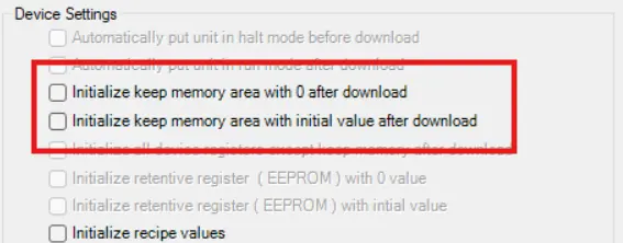
- Initialize keep memory area after download – if checked, Retentive tag values are set to 0 after download is completed. If not checked, the retentive tag values are retained through the download.
- Initialize keep memory area with initial value after download – if checked, all retentive tags will be initialized with their initial values you configured for them in the tag database.
Real Time Clock
The internal battery powers the real-time clock (RTC) when the HMC is not powered by external 24VDC. Normally, the internal battery should be able to provide power to the RTC for approximately 20 years (@25°C).
Reading the Date/Time
The Clock objects (Time and Date) are used to display the date and time on an HMC screen. Each field of the RTC data can also be read and individually displayed on screen by using the designated system word registers (SW10 thru SW16) in the tag database.
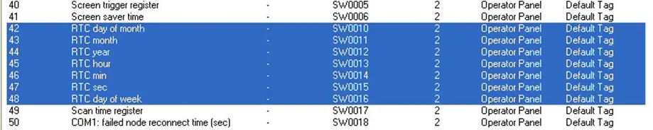
Other reserved registers that pertain to the clock are:
| Tag No. | Tag Name | Tag Address | Description | Access |
|---|---|---|---|---|
| 42 | RTC day of month | SW0010 | Ex: 1-31, Unsigned format | Read Only |
| 43 | RTC month | SW0011 | Ex: 12, Unsigned format | Read Only |
| 44 | RTC year | SW0012 | Ex: 0-99, Unsigned format | Read Only |
| 45 | RTC hour | SW0013 | Ex: 0-23, Unsigned format | Read Only |
| 46 | RTC min | SW0014 | Ex: 0-59, Unsigned format | Read Only |
| 47 | RTC sec | SW0015 | Ex: 0-59, Unsigned format | Read Only |
| 48 | RTC day of week | SW0016 | Ex: 1-7, Unsigned format With 1=Sun…7=Sat | Read Only |
| 5 | Minute Change Status | S00003 | Momentarily sets whenever the minute value in SW14 changes | Read Only |
| 6 | Hour Change Status | S00004 | Momentarily sets when the hour value in SW13 changes | Read Only |
| 7 | Date Change Status | S00005 | Momentarily sets when the date value in SW10 changes | Read Only |
| 8 | Month Change Status | S00006 | Momentarily sets when the month value in SW11 changes | Read Only |
| 9 | Year Change Status | S00007 | Momentarily sets when the year value in SW12 changes | Read Only |
| 12 | RTC battery status | S00010 | Sets when battery is dead | Read Only |
| 17 | Invalid RTC date entry | S00019 | Sets while an invalid value is in one of the RTC registers (HMC2000 only) | Read Only |
| 36 | RTC Status | SW0003_02 | Sets if the RTC is not working (HMC2000 only) | Read Only |
Writing the Date/Time
You can set or change the internal RTC using several means:
- By using the Set RTC task for a function key or one of the multi-task buttons
- By using the Set Calendar (CLND) instruction in the ladder logic commands
- By importing the SetRTC popup screen from an HMC sample project with the same screen size (see below)
You cannot directly write to the clock using the SW106 internal system registers. However, if you wish to write directly, simply use the Numeric Entry object with data registers that are referenced in the Set Calendar instruction in a ladder logic program.
How to import the SetRTC popup screen
Follow the steps below to import the SetRTC preconfigured popup screen.
Instructions: How to import the SetRTC popup screen
Select “Import Screen” option
Choose the [Import Screen] option from the [Screen] menu.Find the default Startup Project File
Find the HMC###### STARTUP.mpl project file for the same HMC model that you are using.These projects are downloaded along with MAPware7000 and can be found in the directory C:\MapleSystems\MAPware7000\Projects\. This is the default directory.Select the screen to import
Import the screen no. 65005 and select the option “Keep Internal Tags”.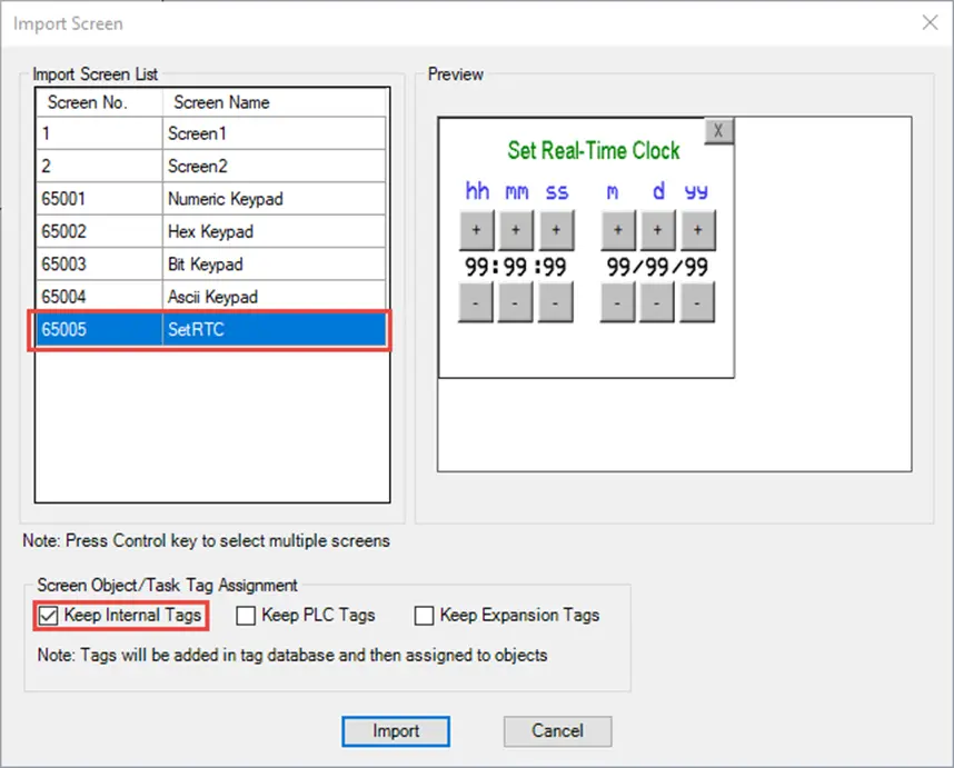
Import
Click the Import buttonPlace the new screen
On a screen in your project, place a “Open Popup Screen” button and set it to open Screen Number 65005.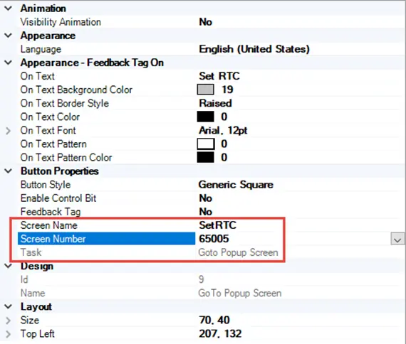
Internal Memory
Each HMC unit has internal memory which can be used for operations. The amount of memory available depends upon which HMC model you have selected. Part of this memory is reserved for specific uses (see Appendix B – System Tag Memory) while the rest of the memory is openly available for your application.
Native Ladder Memory Addresses (Legacy HMC models)
In Native Ladder mode, tags created in the tag database are given explicit addresses which are grouped together into various address types according data format and function. The address type is selected in the Register/Coil Type dropdown box in the Add Tag window (for directions on adding tags to a project refer to Chapter 4 – Tags)
Below is a table that defines the internal memory addresses available in Native Ladder projects. More detail on the function of each type is given in the sections that fallow.
| Type | Name | Range | Type | Access | Description |
|---|---|---|---|---|---|
| Index Register (I) | I00000 | 0 | Register Only (2 bytes) | Read/Write | Index Register |
| Index Register (J) | J00000 | 0 | Register Only (2 bytes) | Read/Write | Index Register |
| Index Register (K) | K00000 | 0 | Register Only (2 bytes) | Read/Write | Index Register |
| Counter Coils | C.0000 | 0-2551 | Bit Only | Read/Write | Counter Coils |
| Counter Registers | C0000 | 0-255 | Register Only (2 bytes) | Read/Write | Counter Registers |
| Timer Coils | T.0000 | 0-255 | Bit Only | Read/Write | Timer Coils |
| Timer Registers | T00000 | 0-255 | Register Only (2 bytes) | Read/Write | Timer Registers |
| Input Coils | X000003 | 0-31015 | Bit Only | Read Only | Physical Input Coils |
| Input Registers | XW00003 | 0-3100 | Register Only (2 bytes) | Read Only | Physical Input Registers Note: Input Coils and Registers share same memory |
| Output Coils | Y000003 | 0-31015 | Bit Only | Read/Write | Physical Output Coils |
| Output Registers | YW00003 | 0-3100 | Register Only (2 bytes) | Read/Write | Physical Output Registers Note: Output Coils and Registers share same memory |
| I/O Configuration Coils | M000003 | 0-31015 | Bit Only | Read/Write | Physical I/O Configuration coils |
| I/O Configuration Registers | MW00003 or MW0000_003 | 0-3100, 0-15 | Bit or Register (2 bytes) | Read/Write | Physical I/O Configuration registers Note: I/O Coils and I/O Registers share same memory |
| System Coils | S00000 | 0-99 | Bit Only | Read/Write | Status and control bits for HMC |
| System Registers | SW0000 or SW0000_00 | 0-255, 0-15 | Bit or Register (2 bytes) | Read/Write | Status and control registers for HMC |
| Internal Coils | B00000 | 0-4095 | Bit Only | Read/Write | General Purpose Internal Coils |
| Internal Registers | BW0000 | 0-255 | Register Only (2 bytes) | Read/Write | General Purpose Internal Registers Note: Internal Coils and Internal Registers share same memory |
| Data Registers | D00000 or D00000_00 | 0-4095, 0-15 | Bit or Register (1, 2 or 4 bytes) | Read/Write | General Purpose Registers |
| Retentive Registers | R00000 | 0-225272 | Register Only (1, 2 or 4 bytes) | Read/Write | Non-volatile memory registers |
1 – The HMC7030 supports C.0000-C.0099
2 – The HMC7030 supports R0-R299, and the HMC7043 and HMC7070 support R0-R1399.
3 – The first two digits of X, XW, Y, YW, M, and MW I/O addresses refer to the slot number of the I/O module. Built in I/O will have an address of 00, while slot 1 would have a prefix of 01.
Note: Memory areas are accessible in the Tag Database under Node Name: [HMC Model] None (-)
Generally speaking, the entire memory area of the HMC can be used for any purpose. However, the memory is split into several classifications so that they can be used for special purposes.
Index Registers (I, J, K)
The HMC Series has three 16-bit index registers (I, J, and K) that perform a specific purpose. As the name implies, these registers are used to ‘index’ or act as pointers to multiple registers. This method is called ‘indirect addressing’ because the HMC does not read/write to the specified address directly. Instead, the target address is determined indirectly by referencing the base address and the value read from the index register.
For example, if the MOV WORD instruction is used in a Ladder Logic Block, you can assign an index register to one of the operands:
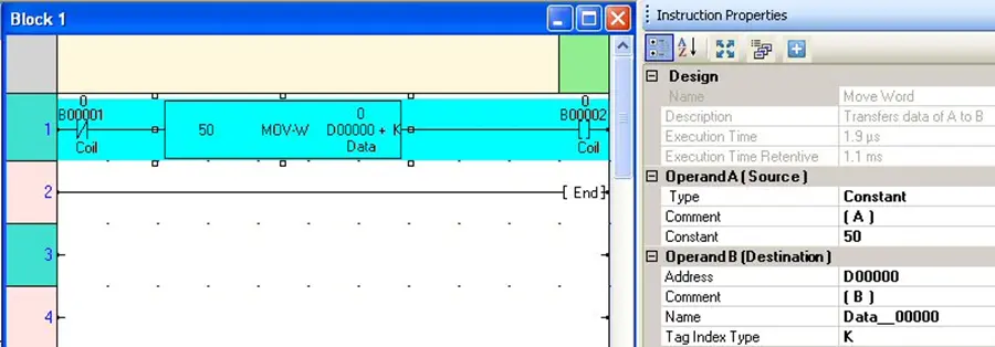
In this example, we use the K index register along with an internal register (D0). When this ladder rung is executed, the HMC reads the value in the K register. It then adds this value to the D0 register (as an offset) to determine the true register that the constant value 50 is written to. If the value in the K register is 1, then the constant value 50 is written to internal memory register D1. If the K value is 2, then 50 is written to internal memory register D2, and so on.
Note: Care should be taken that the value in the index register does not cause the HMC to read/write to a register that does not exist (the address range is not checked by the HMC).
Many of the ladder logic instructions have tag indexing capability. To find out which instructions support this feature, see The HMC Series Ladder Logic Instructions Manual. In each section that defines a particular instruction, you will see an Operand table with a column marked Index. This column is checked for each operand that supports indexing.
Counter and Timer Registers/Coils (C, C., T, T.)
The HMC Series has four memory registers which are specifically used with the Counter and Timer instructions:
- Counter (C) registers
- Counter (C.) coils
- Timer (T) registers
- Timer (T.) coils
Each Timer or Counter register is ‘connected’ to a corresponding Timer or Counter coil. In a Timer or Counter instruction, when the Timer or Counter reaches its set value, the corresponding Timer or Counter coil is set.
For example, the picture below illustrates using the ON Timer:

The timer T00001 register is used to count up to 1 sec (10msec timer). When the preset count (100) has been reached, timer coil T.0001 is set.
Input Registers/Coils (X, XW)
These registers and coils are designed for use by the physical inputs (digital or analog) from an attached or built-in (HMC7030A-L) input expansion module. These are the only internal memory addresses of the HMC which are read only. Therefore, the value read from these registers/coils always represents the current state of the physical input of the expansion module assigned to it. When you start a new project and assign I/O expansion modules to each expansion slot of the HMC, the MAPware will automatically assign the appropriate memory addresses according to slot location. For example, the twelve built-in digital inputs of the HMC7030A-L are assigned to coils X00000-X00011 and register XW0000. For a HMC unit that has eight digital inputs in expansion slot #1, the MAPware software automatically assigns coil addresses X01000-X01007 and register XW0100 to the inputs. If sixteen digital inputs are located in slot#4, the software assigns coil addresses X04000-X04015 and register XW0400 to the inputs. If an analog module with four analog inputs is installed into slot#2, then no coil addresses would be assigned (since these are analog inputs) and registers XW0200-XW0203 are assigned.
The X and XW registers are mapped to the same memory area in the HMC with sixteen X coils per XW register. To determine the register and bit location of an X coil memory area use the following equation: Xnnn = XW(nnn/16 quotient), bit (nnn/16 remainder).
For example, X00161 corresponds to the second least significant bit (bit 1) of XW0010 (161/16 = 10r1).
Output Registers/Coils (Y, YW)
These registers and coils are designed for use by the physical outputs (digital or analog) from an attached or built-in (HMC7030A-L) output expansion module. The value read from these internal registers/coils is used to determine and set the current state of the physical output of the expansion module assigned to it. When you start a new project and assign I/O expansion modules to each expansion slot of the HMC, the MAPware will automatically assign the appropriate memory addresses according to slot location. For example, the eight built-in digital outputs of the HMC7030A-L are assigned to coils Y00000-Y00007 and register YW0000. For an HMC unit that has eight digital outputs in expansion slot #1, the MAPware software automatically assigns coil addresses Y01000-Y01007 and register YW0100 to the outputs. If twelve digital outputs are located in slot#3, the software assigns coil addresses Y03000-Y03011 and register YW0300 to the outputs. If an analog module with two analog outputs is installed into slot#5, then no coil addresses would be assigned (since these are analog outputs) and registers YW0500-YW0501 are assigned.
The Y and YW registers are mapped to the same memory area in the HMC with sixteen Y coils per YW register. To determine the register and bit location of an Y coil memory area use the following equation: Ynnn = YW(nnn/16 quotient), bit (nnn/16 remainder).
For example, Y00161 corresponds to the second least significant bit (bit 1) of YW0010, (161/16 = 10r1).
Configuration Registers/Coils (M, MW)
These registers and coils are reserved to perform special functions when the HMC has built-in or attached expansion modules. For example, the HMC7030A-L has the following I/O Register/Coil memory allocated for the twelve digital inputs and eight digital outputs built into the unit:
- M00240 HSC Enable Bit (ch1)
- M00241 HSC Reset Bit (ch1)
- M00400 HSC Enable Bit (ch2)
- M00401 HSC Reset Bit (ch2)
- MW0000 PLC mode control
- MW0003 Run/Stop Switch
- MW0010 HSC Configuration Register (ch1)
- MW0011 HSC Current Register (ch1)
- MW0013 HSC Preset Register (ch1)
- MW0020 HSC Configuration Register (ch2)
- MW0021 HSC Current Register (ch2)
- MW0023 HSC Preset Register (ch2)
These registers are used when the built-in I/O of the HMC7030A-L is configured as high speed counters.
The MAPware automatically allocates the necessary I/O registers to each expansion module according to slot location and type of module. For example, a HMC unit that has eight digital inputs and eight digital outputs in expansion slot #1 has coil addresses M01080, M01081, M01176, and M01177 and registers MW0100-MW0109 assigned for two high-speed counters. If slot#2 contains an analog 2 input/2 output module, the software assigns no coil addresses and registers MW0200-MS0203 to read/write to the analog registers. When slot#4 contains a 12 point relay output module, MAPware assigns the MW0400 register for relay outputs.
The M and MW registers are mapped to the same memory area in the HMC with sixteen M coils per MW register. To determine the register and bit location of a M coil memory area use the following equation: Mnnn = MW(nnn/16 quotient), bit (nnn/16 remainder).
For example, M00161 corresponds to the second least significant bit (bit 1) of MW0010, (161/16 = 10r1). Individual bits of the MW registers can be accessed with using the MW0000_00 notation, so the previous example would be written as MW0010_01.
System Registers/Coils (S, SW)
These registers and coils are reserved by the HMC for specific purposes. A total of 100 system coils and 256 system registers are reserved. Although undefined system registers and coils could be used by the HMC programmer, this area of memory may be used in the future for predefined uses. Therefore, use of this area of memory should be limited to the predefined coils and registers. For a list of these memory areas, see Appendix B – System Tag Memory.
Internal Registers/Coils (B, BW)
These are general purpose registers and coils which can be used at the discretion of the HMC programmer. This area of memory is non-retentive so any data stored in these registers is lost once power has been removed from the HMC.
The B coil memory and the BW register memory are mapped to the same memory area in the HMC with sixteen B coils per BW register. Therefore, the least significant bit in register BW0 corresponds to the B0 coil. Likewise, the B18 coil shares the same memory area as bit 2 of BW1. To determine the register and bit location of a B coil memory area use the following equation: Bnnn = BW(nnn/16 quotient), bit (nnn/16 remainder).
Therefore B00050 coil corresponds to BW0003, bit 2 (50/16 = 3r2).
Data Registers (D)
These are general purpose registers which can be used at the discretion of the HMC programmer. This area of memory is non-retentive so any data stored in these registers is lost once power has been removed from the HMC.
Note that these registers can be configured as bits with the D00000_00 notation.
Retentive Registers (R)
These are general registers which can be used at the discretion of the HMC programmer. This area of memory is retentive so any data stored in these registers remains once power has been removed from the HMC.
Note that reading/writing to these registers requires more processing time than does using any of the other registers in memory due to their retentive nature. Therefore, be aware that using these registers in ladder logic blocks require more processing time.
IEC 61131-3 Tags (HMC2000 and HMC4000 models)
In projects created using the IEC 61131-3 programming mode, tags are not, necessarily, assigned an explicit memory address. Instead they are created with a data type that determines the tags format and function. The data type is selected in the Register/Coil Type dropdown list in the Add Tag window of the tag database. For detailed instructions on creating tags refer to Chapter 4 – Tags.
Below is a table displaying the tag data types available in IEC 61131-3 projects.
| Data Type | Description | Bits | Value Range |
|---|---|---|---|
| BOOL | Boolean value can have one of two values: 1 (ON / True) or 0 (OFF / False) | 1 | 0 or 1 |
| BYTE | Unsigned Short (same as USINT) | 8 | 0 to 255 |
| DINT | Signed Double Integer | 32 | -2,147,483,648 to 2,147,483,647 |
| DWORD | Unsigned Double Integer (same as UDINT) | 32 | 0 to 4,294,967,295 |
| INT | Signed Integer | 16 | -32,768 to 32,767 |
| LREAL | IEEE 754 format, double precision floating point | 64 | |
| REAL | IEEE 754 format, single precision floating point | 32 | ±3.403 x 1038 |
| SINT | Signed Short Integer | 8 | -128 to 127 |
| STRING | Variable length string of ASCII characters | 1 to 255 bytes | N/A |
| TIME | Time of day | 32 | N/A |
| UDINT | Unsigned Double Integer (same as DWORD) | 32 | 0 to 4,294,967,295 |
| UINT | Unsigned Integer | 16 | 0 to 65,535 |
| USINT | Unsigned Short Integer (Same as BYTE) | 8 | 0 to 255 |
| WORD | Unsigned Integer (Same as UINT) | 16 | 0 to 65,535 |
In addition to these data types, IEC 61131-3 projects share some of the data types available in Native Ladder projects. In these cases the tags are given an explicit address which is visible in the tag database. These registers are; Retentive Registers (R), System Coils / Registers (S, SW), Input Registers (X, XW), Output Registers (Y, YW), and I/O Configuration Coils / Registers (M, MW). Refer to the previous section of this page for information on available addresses and using these registers.