
Overview
Function Block Diagram is a graphical programming language in which program operations are represented as labeled, rectangular blocks. Input and output parameters are shown as labels attached to the blocks. Inputs are attached to the left and outputs to the right.
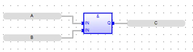
Inputs can be tags or literal values.
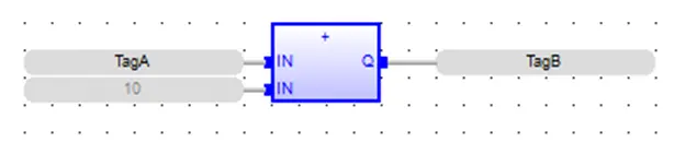
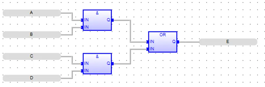
Function Blocks can be connected together so that the outputs of one block become the inputs of another. This allows the programmer to build complex operations out of simple building blocks.
Function Block Diagram vs. Ladder Diagram
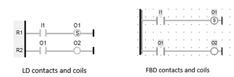
Unlike LD programming, FBD programming does not require the use of power rails for the Function Blocks:
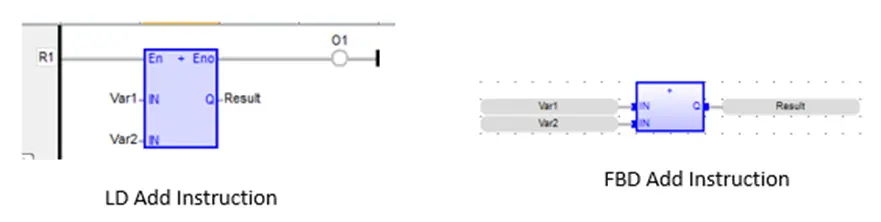
Therefore, with FBD programming, there are no En (Enable or activate instruction) or Eno (Enable output) connections. This means that each Function Block (instruction) is always executed in FBD programming (unless skipped). For this reason, FBD programming is most often used when the order of execution is not as important. Rather, the focus is on creating function blocks (instructions) that process data when the logic block is executed. There is much less emphasis on enabling/disabling functions using contacts in FBD.
However, the FBD editor does contain left power rail, contact and coil objects that can be added to the program using the quick start menu. When using power rails, contacts and coils, both programming languages are very similar:
- every contact requires a connection to the left power rail
- every contact requires that the output be connected to another contact, instruction or coil
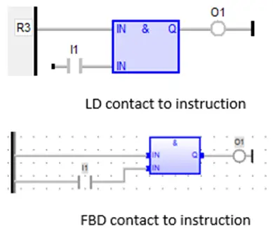
You can connect a contact directly to the input of a Function Block that requires a Boolean value:
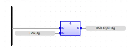
This is equivalent to using a Boolean tag as the input:
In LD programming, instructions are executed starting with the top rung, then the next rung, and so on. Since FBD programming doesn’t require rungs, all objects are executed from Left to Right and Top Down.
Adding Logic to the Block
There are two main ways to add elements to the block:
- Using the Quick Select Menu
- By dragging instructions from the Instruction List
Function Block elements have input(s) on the left side and an output(s) on the right side. When connecting elements, you can only connect one object’s output to another object’s input.
For example, suppose you wish to connect a contact to a coil.
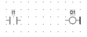
To connect the two, you would simply select the Arc Tool and then connect the two objects:
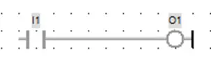
As stated above, if you do this by clicking the input I1, then move to the output O1, you will have no problem connecting the two. However, if you try clicking the output O1, then move to input I1, they will not connect. Why? Because the software is assuming that you want to connect the output of the coil O1 to the input of the contact I1- which is not allowed. Generally speaking, you will find it is much easier to connect objects if you start from the left side and move to the right. Also, don’t forget to connect the input of I1 above to the left power rail.
Similarly, you might want to connect two contacts in parallel:
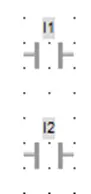
You might try to do this by simply clicking the output of I1 then clicking the output of I2. This is what you would get:
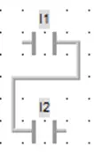
Why? Although you are correctly starting with the output of I1, the software thinks you want to connect to the input of I2. To create a parallel connection, you must use the OR bar (more on this tool later).
Note: When adding components to a FBD block, open connections will cause a compiler error.
Quick Select Menu
Options available in the FBD editor Quick Select Menu are:
Selection
The selection tool is used to select one or more objects already on the editor work area to delete, move, highlight, etc. Note: when using any of the quick select options below, you will notice that your mouse cursor remains defined as that quick select option even after you have used it to place the object in the work area. For example, after placing a function block on the work area using the Add Function Block option, the mouse cursor continues to be defined as an Add Function Block so that you can easily place additional function blocks on the work area.
To be able to select an existing object in the work area, you must click the Selection quick select option. Another way to do this is move the mouse cursor to a blank area in the work area, then right-click the mouse. This will change it back to the Selection quick select option.
Add Function Block
Click to add a function block to the editor work space. Click this option then click in the editor work space. This will place an AND (&) function block with no variables inputs connected to it.
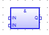
Click again to add another function block or right-click to switch back to the select tool.
To change the function block type, drag the function block you’d like to change the default “&” block to, and drop it on top of the default “&” block.
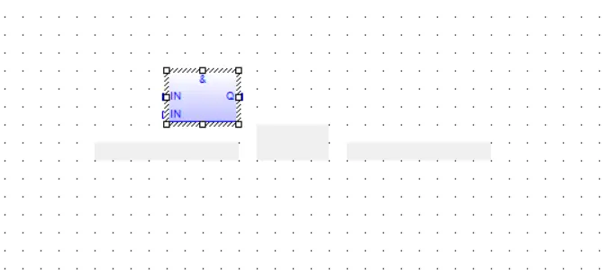
The logic blocks inputs and outputs can be connected to other elements or to variables using the Add Variable option.
Add Variable
Places a variable field on the logic work area:
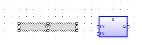
A variable field is used to connect tags to the inputs or outputs of function blocks that are not connected to other function blocks or to other elements. If you drag the function block from the Instruction List into the editor it will already have the required variable fields attached. Function blocks added using the quick select menu will not have variable fields attached. To place a Variable Field, click the Add Variable icon, move the mouse cursor to where you wish to place the Variable Field in the editor work area, then click the mouse cursor. Note: if the Variable Field (VF) does not appear after you click the mouse cursor, this means that you are placing the VF too close to another object. Once the VF has been placed on the work area, you must connect it to either a FB input or output. Move the mouse cursor to one side of the VF until the cursor changes to a crosshair:
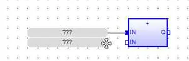
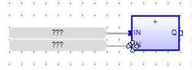
Click and Drag the mouse cursor over to the FB input, until another crosshair cursor appears, then release:
Add Comment
Places a comment block on the logic work area.
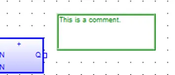
A comment block can be used to provide a description of the FBD or a particular object. To place a Comment Block (CB), click the Add Comment icon, move the mouse cursor to where you wish to place the CB in the work area, then click the mouse cursor. Note: if the Comment Block (CB) does not appear after you click the mouse cursor, this means that you are placing the CB too close to another object. Once the CB has been placed on the work area, double-click to display an input field:
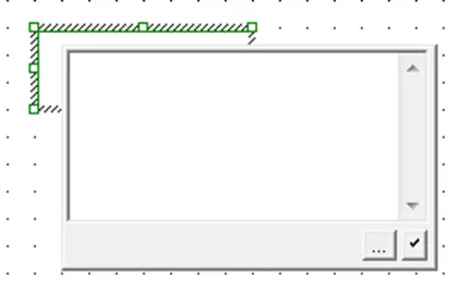
Enter text then click the accept button. The browse button is used to open Windows File Explorer. You can then select a bitmap image that can be placed in the comment block.
Add Arc
An arc is used to link the output of one object to the input of another.
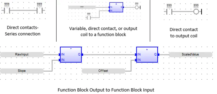
You can initiate using the Arc tool by clicking the Add Arc quick access key, then pointing the mouse cursor at any object’s out point. This will cause the mouse cursor to change to a crosshair .
Click/drag the mouse cursor to the second object’s in point. When the crosshair appears again, release the mouse cursor:

Add Corner
How to add corner
This tool adds a junction point to an arc, thus providing the ability to branch to more than one object (to the input of those objects). For example, suppose we want to connect one contact to three coils:
Create the objects to be connected
Place one contact and three coils in the workspace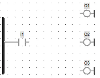
Start with Arc Tool
Use the arc tool to draw a connection between I1 and O1: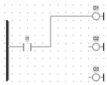
Use Corner Tool
Use the corner tool to place a corner somewhere on the connecting rung: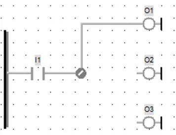
Arc tool to connect
Use the arc tool to connect the corner to the other two outputs:Note that the arc tool only works when trying to connect the output of one object to multiple inputs of other objects.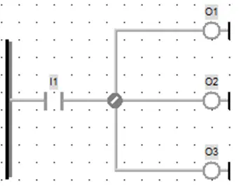
Add Break
Inserts a network break (horizontal line).
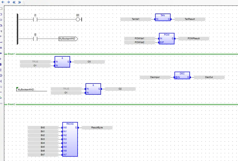
The network break does not affect the operation of the FBD code. It is only used to help make complex diagrams easier to read by splitting the diagram into networks. To place a break there must be a horizontal section of the editor work area with no objects on it.
Add Label
The label is used along with the Jump tool (see below) to skip (not execute) the segment of code between the Jump statement and the Label, when the Jump statement is active. Labels used without a corresponding Jump can be used to simply provide a description of some segment of the FBD logic block. See the section on Jumps and Labels for more information.
Add Jump
Inserts a Jump statement. The Jump is used with the Label to cause code execution to be redirected. See the section on Jumps and Labels below for more information.
Add Left Power Rail
This tool is used to place a left power rail on the FBD. Similar to LD programming, whenever you use contacts, you must tie them to a left power rail:
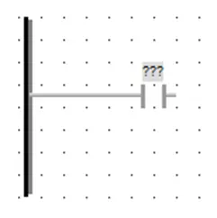
- You can resize the power rail to any length you need or you can place multiple power rails on the FBD
- When placing a direct contact on the FBD, if you first place the left power rail, then place a direct contact- the software will automatically tie the two together.
The left power rail can be placed anywhere on the FBD (it does not have to be on the left side).
Add OR bar
The OR bar is required to tie the outputs of multiple direct contacts for a parallel connection:
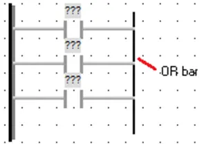
You can also use it to tie the outputs of multiple variables:
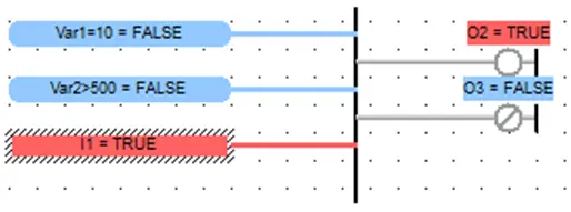
Notice above that you can also tie the OR bar to the inputs of multiple direct coils. Every OR bar must have at least one input and one output tied to it.
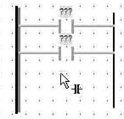
The fastest way to connect multiple direct contacts in parallel is to:
- Place a Left Power Rail on the FBD
- Place an OR bar on the FBD
- Place a direct contact between the Left Power Rail and the Or bar. The software automatically connects the elements.
Add direct Coil
A direct coil can be used to activate a physical output coil or as a result of code that it is tied to. Direct coils can be placed on the FBD in series or in parallel circuits:
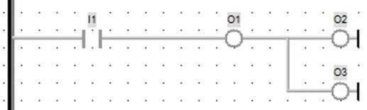
Add Right Power Rail
The Right Power Rail can be used to complete a rung circuit.
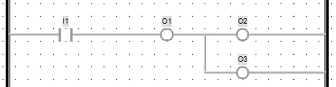
However, for FBD programming it is not necessary to have any direct coils connected to the right power rail. In fact, you don’t have to use the Right Power Rail for any connection. It is provided as a convenience for users who are experienced with traditional ladder logic and wish to have it depicted in the FBD.
Swap Item Style
Changes the style of the highlighted contact or coil. The options cycle each time you click the Swap Item Style hotkey. See the section on Changing Item Style below for available contact and coil execution styles.
Connect Two Items
This tool can be useful if you need to connect two function blocks or other items that are far apart on the editor screen. First, using the select tool, hold down the <Ctrl> key and click both items you want to connect. A popup window will appear with both selected items next to each other.
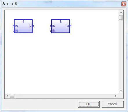
Use the popup window to connect the outputs to the inputs as if the window were the main editor window. Click OK and the software will draw the full connection in the main editor window automatically.
Show Execution Order
In general, code execution in an FBD logic block moves from left to right, top to bottom. Since function blocks are not required to attach to a left power rail function blocks can be floating in the editor window and it can be difficult to see the exact order. This tool will show you the execution order MAPware-7000 has assigned to all the blocks in the editor:
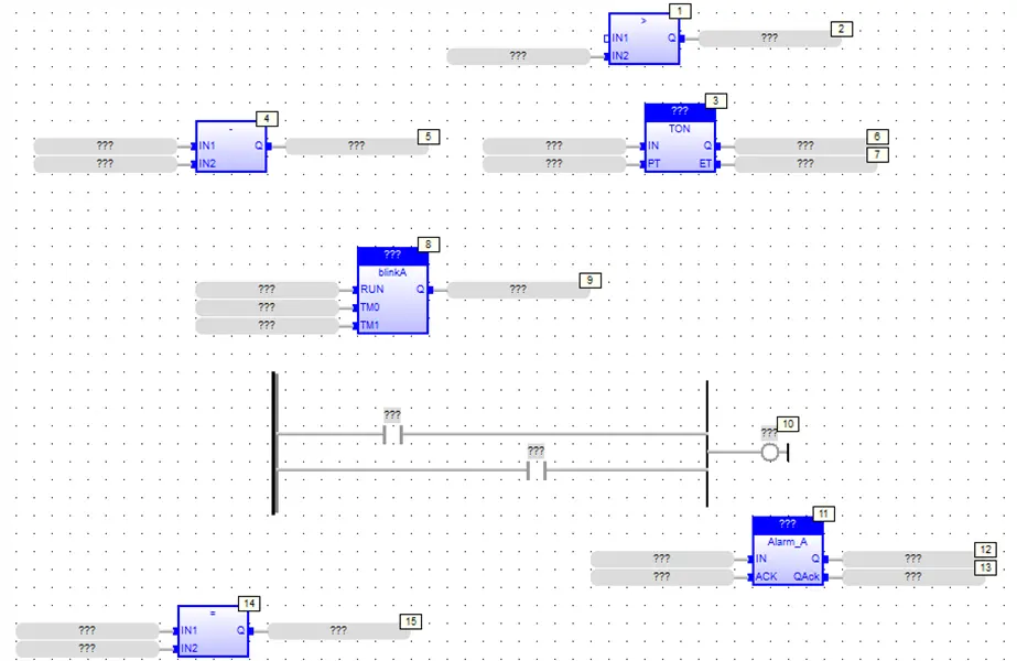
Note: The Show Execution Order tool is used only to show the execution order- you cannot change the order of execution using this tool.
Add Vertical Rule
Similar to the Add Break tool, the Vertical Rule can be used to place vertical dotted lines on the FBD work area:
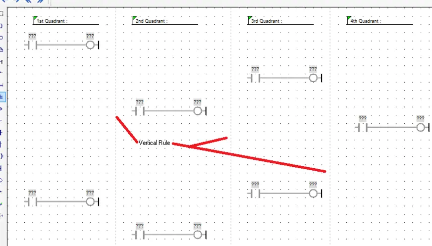
Vertical Rules have no effect on code execution- the only purpose is to split the FBD logic block into easier to read sections.
Once placed, you can move a vertical rule by moving the mouse cursor until it changes to a double-arrow:
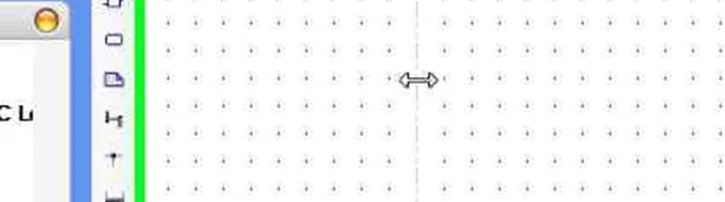
Now click and drag to the new location. To delete a vertical rule, move the cursor until a double-arrow displays, then double-click the mouse.
Changing Contact and Coil Execution Style
As with real relays, there are several configurations available for contacts and coils in the Function Block Diagram editor. To change the execution style of an element, select that element in the editor window and click the Swap Item Style icon in the Quick Select menu, or press space on your keyboard.
Contact Execution Styles
The available execution styles for contacts are:
- Normally Open Contact – If the value of the tag controlling the contact is 0 (false) no power flows through contact. If the value of the tag controlling the contact is 1 (true) power flows through contact.
- Normally Closed Contact – If the value of the tag controlling the contact is 1 (true) no power flows through contact. If the value of the tag controlling the contact is 0 (false), power flows through contact.
- Positive (Rising Edge) Pulse Contact – if the value of the tag controlling the contact transitions from 0 (false) to 1 (true), power flows through contact for one scan only.
- Negative (Falling Edge) Pulse Contact – if the value of the tag controlling the contact transitions from 1 (true) to 0 (false), power flows through contact for one scan only.
Coil Execution Styles
The available execution styles for coils are:
- Normal Coil Output – The tag controlled by the coil is set to 1 (true) as long as power flows to the coil. The tag is set to 0 (false) when power does not flow to the coil.
- Inverted Coil Output – The tag controlled by the coil is set to 0 (false) as long as power flows to the coil. The tag is set to 1 (true) when power does not flow to the coil.
- Set Coil Output – The tag controlled by the coil is set to 1 (true) when power flows to it. The value of the tag will stay at 1 even after power no longer flows. This is also referred to as a latch instruction.
- Reset Coil Output – The tag controlled by the coil is set to 0 (false) when power flows to the coil. The value of the tag will stay at 0 (false) when power no longer flows to the coil. This is also referred to as an unlatch instruction.
Adding Function Blocks from the Instruction List
In addition to using the Add Function Block quick select menu option, you can simply click-drag on a function block in the Function Block List and drag to the work area:
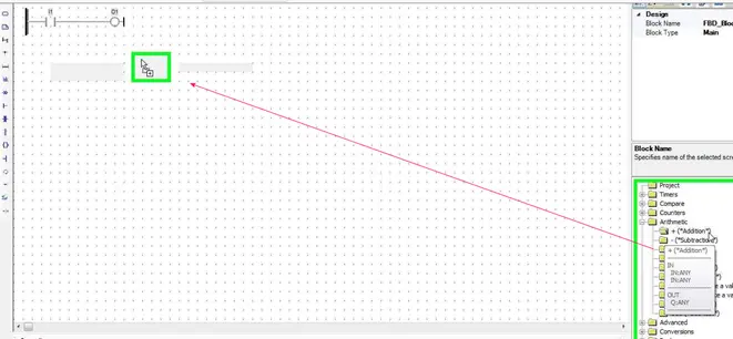
Place the Function Block (instruction) on the FBD work area.
The function block will be configured with Variable Labels for each input and output. These can be configured with tags, or deleted to connect the function block to another function block or element.
Assigning Inputs and Outputs to FBD elements
After a contact, coil or function block is placed in the editor window, tags must be assigned. To select a tag double-click the element you are trying to configure. A tag selection box will be displayed.
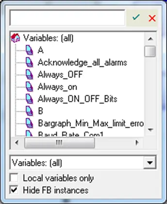
You can scroll through the variable list to find an appropriate tag. If the tag name is known, begin typing the name in the text box and matching tags will be available for auto complete. Once the tag is selected press Enter or the green checkmark to assign the selected tag.
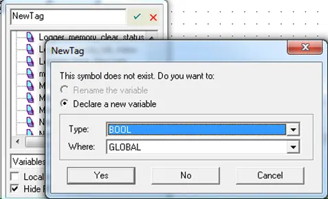
If no tag exists with the name entered, a popup window will appear allowing a new tag to be created.
Selecting Function Block Instances
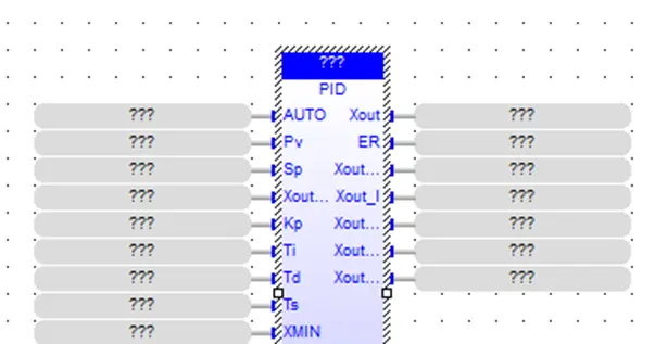
User Defined Function Blocks and many of the built in Function Blocks require that an instance of the function block be selected so that the block can operate on its own set of data. If this is the case, the function block will appear with a set of question marks above the type of the block.
To select an instance to use, simply double-click the question marks to display the Tag selection window. Function Block Instances will appear in this window along with normal tags. Make sure that the Hide FB instances checkbox is not checked.
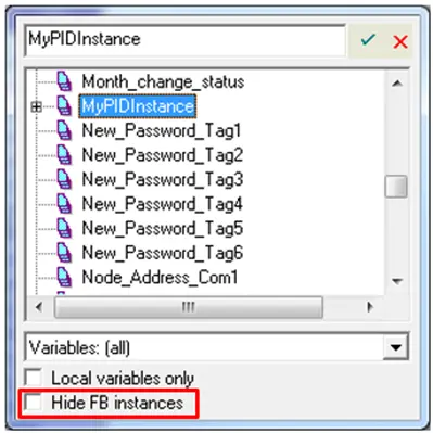
The list of available Function Block Instances can be found in the Function Block Instance folder of the Project Information Window. The type of the function block instance must be the same as the function block being configured. If there is a mismatch this will cause a compiler error.
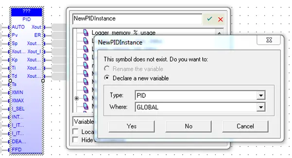
To create a new instance, simply type the name for the new instance in the text box and hit enter. A popup window will appear allowing the new instance to be configured. The new instance is automatically added to the Function Block Instance folder.
Jumps and Labels
Jumps and Labels allow function blocks to be conditionally skipped (not executed). When a Jump statement is active, the segment of code between the Jump statement and the Label will be skipped. Jump and Label elements can be placed in the editor window using the quick select menu options.
Note: Jumps skip function blocks based on their execution order which is determined by the location of the function block in the editor. Because function blocks can “float” in the editor window execution order can be ambiguous to the naked eye. To see the execution order MAPware-7000 has assigned to elements use the Show Execution Order quick select tool ( ).
To see how Jumps and Labels operate, consider this Function Block Diagram:
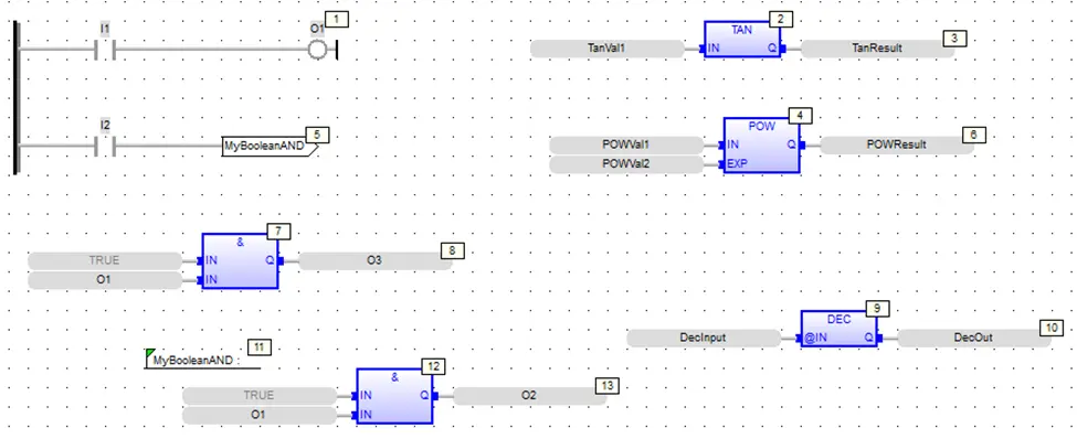
Notice a Jump statement at location with the name: MyBooleanAND. Note the Label statement at location with the same name. During execution of this FBD, when input contact I2 is active, the jump statement is activated. This causes the code execution to skip all code between the jump statement and the label statement (locations 6-10).
To implement the label, click the Label tool and place a label on the FBD:
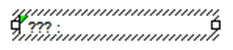
Double-click the label to display the Edit popup window:
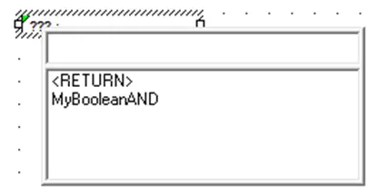
The <RETURN> statement and any Jump statements that have been created are displayed as a list. You can select from the list or enter a new label name.
The <RETURN> statement is a special instance that behaves a little differently. If a Jump statement and a Label statement are assigned to <RETURN>, when the Jump statement is activated, code execution immediately goes to the Label <RETURN>:
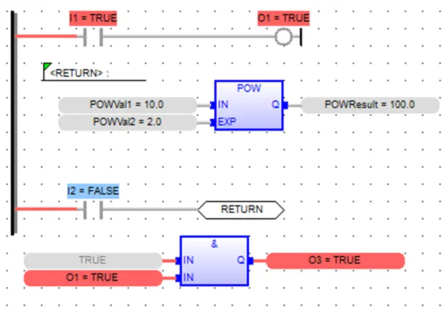
In this example, input contact I2 is off so the Jump <RETURN> is not activated. Therefore, code execution proceeds as normal- with I1 in the first rung setting coil O1. The POW function is executed and the AND function at the bottom is executed.
If we set input contact I2 true, then the Jump <RETURN> is activated:
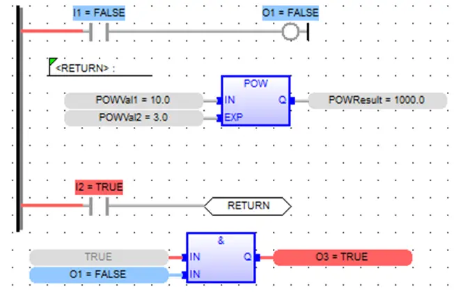
- Now, when we reset input contact I1 to OFF, output coil O1 is set off.
- If we change the inputs to the POW function, the output is updated.
- However, notice that since the Jump <RETURN> is now active, code execution immediately goes to the Label <RETURN> statement- causing a loop in which only the POW statement is executed.
- Notice the AND function after the Jump <RETURN> statement. Although O1 is now False, output O3 remains True since the code is not executed.
The code is now a continuous loop until I2 is reset back to False.