
Overview
The Ladder Diagram editor provides a graphical representation of the logic block in the form of a schematic of an electro-mechanical circuit. The diagram consist of vertical left and right power rails and logic in the form of horizontal rungs that connect the left power rail to the right. The programmer constructs the logic by adding circuit elements to the horizontal rungs.
There are three main types of elements that can be placed on a Ladder Diagram logic rung:
- Contacts – These represent the contact terminals of an electro-mechanical relay. They have two states represented by the state of a Boolean tag. In a contact the state of the tag controls the state of the element, therefore these are generally used as inputs controlling the state of elements placed further to the right along the rung.
- Coils – These elements are represented by the coil of an electro-mechanical relay. They also have two states represented as the state of a Boolean tag. In a coil the state of the elements controls the state of the tag, therefore coils are used as outputs of the logic rung, controlled by elements placed to the left closer to the power rail.
- Function Blocks – These are more complex operations. They can have several input tags of various types and several output tags of various types. They can also contain quite complicated internal logic as in the case of subroutines and UDFBs.
Power flows through the circuit diagram from the left power rail, through the logic of the rungs, to the right power rail. Contacts and function blocks placed on the left side of a rung (closer to the left power rail), conditionally determine whether power flows to contacts coils and function blocks placed further to the right on the rung. If power is allowed to flow to a coil or function block, that coil or function block is said to be energized. When energized, an output’s state is set according to the style of the output. When a function block is energized, the function block operation is executed. If the power is blocked from reaching an output or function block, that output or instruction is said to be de-energized. When de-energized, an output will be set according to the style of the output. A de-energized function block will not be executed and its outputs will not be updated.
Just as in a real circuit, elements can be connected together either in series (one after the other on the same conductor with no branches or junctions), or in parallel (each connected to its own branch from the same junction point).
When contacts are connected together in series this creates a logical AND operation. All of the contacts have to be closed in order for power to flow to downstream circuit elements. When contacts are placed in parallel this creates a logical OR operation. When any one of the contacts is closed power will flow to downstream circuit elements.
Coils and function blocks can also be connected in parallel allowing a single input condition to control several outputs. Series and parallel connections can be combined to create arbitrarily complex logic networks.
Execution Order
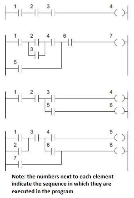
In a real circuit, when a junction point is energized all of the circuit elements attached to that junction point are energized simultaneously. In a Ladder Diagram program this is not the case. The processor can only evaluate one circuit element at a time. The order in which this execution occurs will affect how the program functions. The rules for the order in which circuit elements are evaluated are as follows:
- Rungs are executed from top to bottom
- When there is no parallel connection, each element on the rung is executed from left to right.
- When a junction point is encountered, each branch of the junction is evaluated in turn, from left to right starting with the top branch and moving towards the bottom branch.
- When a junction point is encountered to the right of a circuit element, elements to the right of the junction point are not evaluated until all branches to the left have been evaluated. Branches are evaluated left to right, top to bottom.
This graphic gives some examples of these rules in practice:
Creating a Ladder Diagram logic block
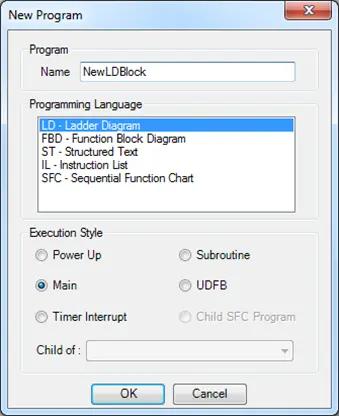
To create a new LD logic block, right-click the folder of the project tree for the desired Execution Style (see the section on Execution Styles in Chapter 1 for more information). Enter a Name for the logic block, select LD-Ladder Diagram for the Programming Language, and click OK.
The Ladder Diagram Editor Window
Once the block is created the Ladder Diagram Editor Window will be displayed.
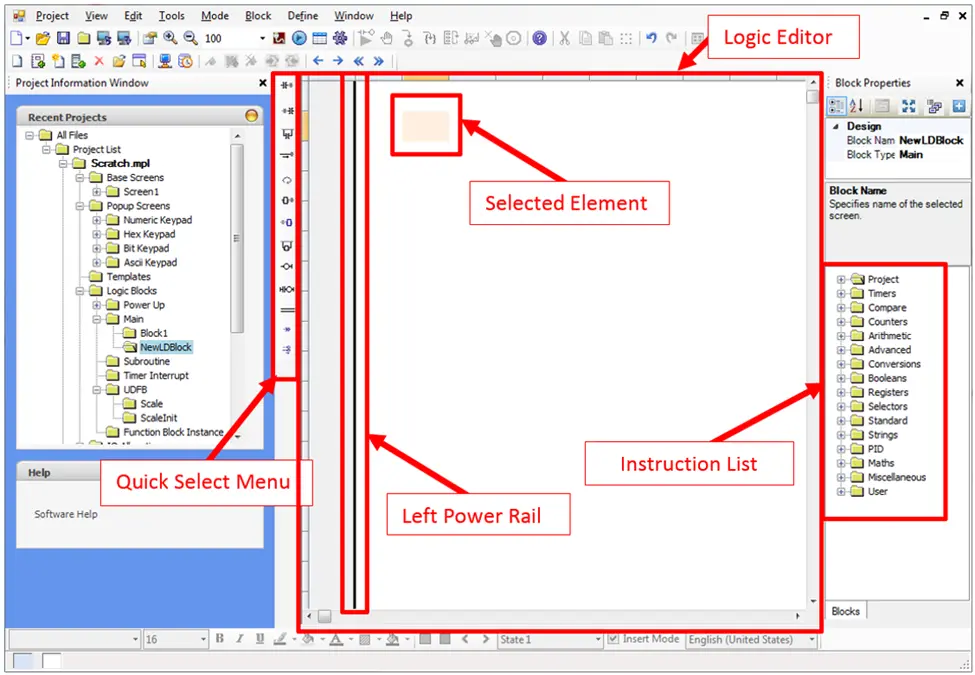
The important elements of this window highlighted in red above are:
- Quick Select Menu – provides a convenient way to quickly add contacts, outputs and function blocks to a rung.
- Left Power Rail – represents the source of power of all instructions added to a rung. In order to energize an instruction or output it must be connected to this power rail. In order to energize an instruction or output it must be connected to this power rail. The right power rail is not shown as a continuous vertical rail and is assumed to be connected to the right side of the rightmost element on a rung.
- Logic Editor – contains all of the rungs/instructions in the Ladder Diagram logic block.
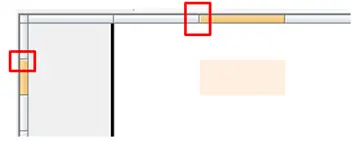
- Selected element – the active element that will receive input from user actions on the Quick Select Menu or the keyboard. Note that the space available for the selected element can be adjusted by clicking and dragging the edge of the editor column or row:
- Instruction List – A list of available Function Blocks that can be added to the Ladder Diagram. Click and drag an instruction into the Editor Window to use it on a rung.
Adding Logic to the Block
For the logic block to do anything it must contain rungs with contacts (inputs), coils (outputs) and or function blocks. There are two main ways to add elements to the block:
- Using the Quick Select Menu
- By dragging instructions from the Instruction List
Using the Quick Select Menu
The options in the Quick Select Menu are:
- Insert Contact Before – Inserts a contact on the rung before the selected element.
- Insert Contact After – Inserts a contact on the rung after the selected element.
- Insert Contact Parallel – Inserts a contact that is in parallel with the selected element.
- Insert Horizontal Line – Inserts a horizontal line at the selected element.
- Swap Item Style – Changes the execution style of the highlighted contact or coil. The options cycle each time you click the Swap Item Style icon. The available options are explained in the Changing Contact and Coil Execution Style section below. Pressing the keyboard space bar is equivalent to selecting this item.
- Insert FB Before – Inserts a function block before (to the left of) the selected element
- Insert FB After – Inserts a function block on the rung after (to the right of) the selected element
- Insert FB Parallel – Inserts a function block on a branch parallel to the selected element.
- Insert Coil – Inserts an output coil at the end of the selected rung.
- Insert New Rung – Inserts a new rung with one contact and one coil above the rung of the selected element.
- Insert Comment – Inserts a comment line above the area selected. See the section on Comments for more information.
- Insert Jump – Insert a jump instruction.
- Align Coils – Positions all of the output coils so that they are vertically aligned
Changing Contact and Coil Execution Style
As with real relays, there are several configurations available for contacts and coils in the Ladder Diagram editor. To change the execution style of an element, select that element in the ladder diagram editor window and click the Swap Item Style icon in the Quick Select menu, or press space on your keyboard.
Contact Execution Styles
The available execution styles for contacts are:
- Normally Open Contact – If the value of the tag controlling the contact is 0 (false) no power flows through contact. If the value of the tag controlling the contact is 1 (true) power flows through contact.
- Normally Closed Contact – If the value of the tag controlling the contact is 1 (true) no power flows through contact. If the value of the tag controlling the contact is 0 (false), power flows through contact.
- Positive (Rising Edge) Pulse Contact – if the value of the tag controlling the contact transitions from 0 (false) to 1 (true), power flows through contact for one scan only.
- Negative (Falling Edge) Pulse Contact – if the value of the tag controlling the contact transitions from 1 (true) to 0 (false), power flows through contact for one scan only.
Coil Execution Styles
The available execution styles for coils are:
- Normal Coil Output – The tag controlled by the coil is set to 1 (true) as long as power flows to the coil. The tag is set to 0 (false) when power does not flow to the coil.
- Inverted Coil Output – The tag controlled by the coil is set to 0 (false) as long as power flows to the coil. The tag is set to 1 (true) when power does not flow to the coil.
- Set Coil Output – The tag controlled by the coil is set to 1 (true) when power flows to it. The value of the tag will stay at 1 even after power no longer flows. This is also referred to as a latch instruction.
- Reset Coil Output – The tag controlled by the coil is set to 0 (false) when power flows to the coil. The value of the tag will stay at 0 (false) when power no longer flows to the coil. This is also referred to as an unlatch instruction.
- Positive Pulsed Coil Output – The value of the tag controlled by the coil is set to 1 (true) for one scan only when the power that flows to the coil transitions from off to on.
- Negative Pulsed Coil Output – The value of the tag controlled by the coil is set to 1 (true) for one scan only when power that flows to the coil transitions from on to off.
Function Blocks
Function Blocks will sometimes need to be configured after they are placed. You may need to select a different function block, select a function block instance to use, or simply configure the function block inputs and outputs.
Adding a function block
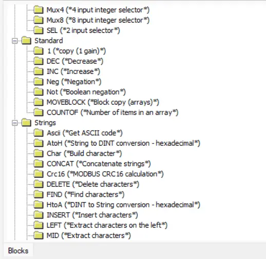
Adding a function block to your ladder diagram is as simple as dragging the function block type from your instruction list (from the bottom right corner of the editor window).
Selecting a Function Block Instance
Some function blocks require that an instance of the function block is added to the project before the block is used. If this is the case, a set of question marks will appear above the function block.
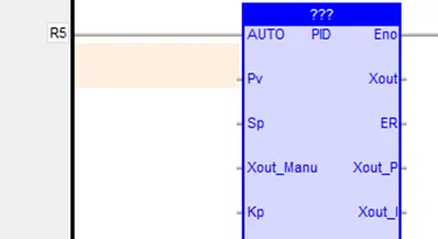
Double-click the question marks and select the desired instance from the popup window.
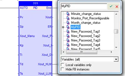
If there is no instance of this block created yet, simply type the name of the instance you want to create in the search field and hit enter. The instance will be created with the correct type and selected for use in this ladder element.
Configuring Input and Output Parameters
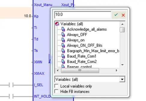
Function blocks can have many input and output parameters. To configure a parameter, simply double-click the input or output and select the desired tag from the popup window.
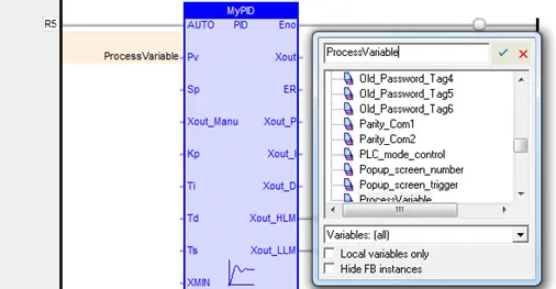
If a suitable tag has not yet been created, you can type the name of a new tag and hit enter. A popup window will appear, allowing you to configure the tag. When finished, the tag is added to the tag database.
You may also use literal values (static numbers that don’t change) as inputs to function blocks, by typing the value in the tag selection popup window.
Function Block Enabled and Enabled Output Fields
As mentioned in the overview section, Function Blocks are represented as circuit elements that do more complicated functions than simple inputs and outputs. For the operation to take place, the Function Block needs to be attached to an activated rung (one where power is able to flow from the left power rail). The point of attachment is the Enable (En) input.
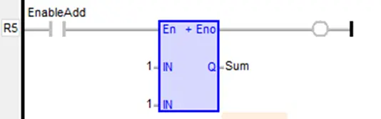
The logic in the function block will not be executed unless this input is true.
Function Blocks will also have an Enable (Eno) output. This allows an output coil to be activated, indicating that the function block is active. This also allows multiple function blocks to be connected in series.
Jumps
A jump is a simple way to skip a section of logic. Here is a simple example:
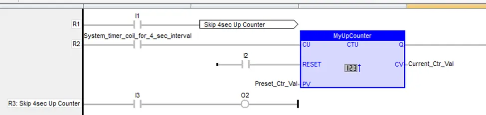
The Up Counter on Rung #2 increments every 4 seconds until it reaches the preset value. To temporarily halt operation of the Up Counter, we could use the Jump command, which is on Rung #1. When input I1 is on, the Jump command forces the HMC/MLC to jump to Rung #3 (Skip 4sec Up Counter), thus not executing any code between (in this case, Rung #2).
To implement a jump command, you must first assign a label to the rung that the code will jump to. Double-click in the grey column area (left of the logic code area) on the rung that needs a label:
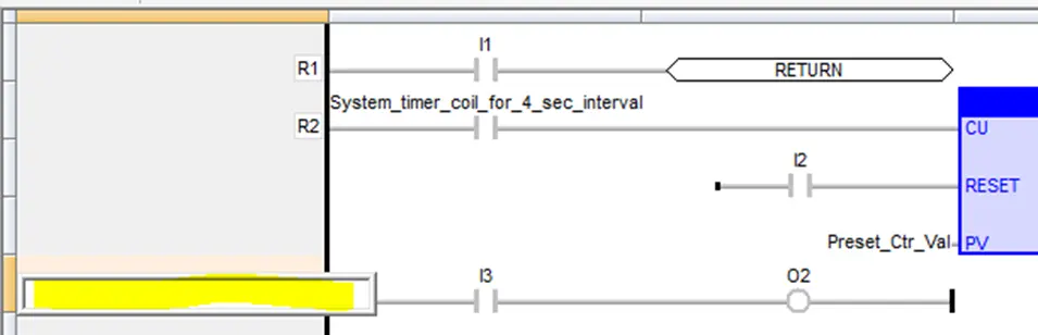
Enter a unique label name.
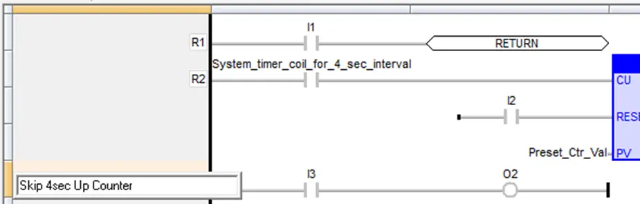
Then press Enter. Now insert a jump command on an existing or new rung:
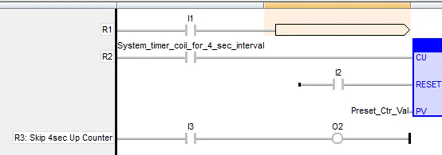
Double-click the jump command to display a popup window that shows all of the current rung labels (as well as a Return command):
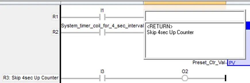
Double-click the appropriate rung label.
Comments
Comments are a great way to document a logic block. To add a comment simply click the add comment option in the Quick Select Menu. This will put a single line comment above the selected element.
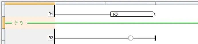
To fill in the comment double-click anywhere on the comment line and enter the comment text.