HMC Basics
An HMC is a combination operator-based HMI (human machine interface) with built-in PLC (programmable logic controller) operation and expandable I/O.
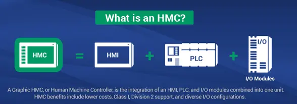
HMCs offer flexibility. Rather than using fixed I/O, the HMC employs expansion slots to customize your I/O configuration. Maple Systems offers a wide assortment of expansion modules including combination digital input/output modules, digital input only, digital output only, analog modules, and high-speed counter modules. For more information on the different I/O configurations available, see the appropriate HMC family I/O Module Guide for your model.
Backing Up Projects
The MAPware-7000 configuration software does not perform automatic saves of the open project. We recommend that you frequently save your project as you are working on it to ensure that no work is lost in the event of a power failure or computer error. When you have completed a project, archive it to another folder, external network drive, or storage media for safekeeping. To archive your project, backup both the .mpl file and the corresponding file folder located in the same directory.
Although Maple Systems does provide repair support on all of our products, we cannot guarantee that we will be able to restore a project from a damaged unit.
Logic Editor Environment
MAPware-7000 includes a full-featured set of logic editors. There are two options for configuring PLC logic in a MAPware-7000 project: Native Ladder and IEC 61131-3. This selection is made in the Programming Language drop down list when a project is first created.
Native Ladder Editor
The Native Ladder Logic editor is a Ladder Diagram editor. Ladder logic is a programming language that represents a program with a graphical diagram based on the circuit diagrams of relay logic hardware. Ladder logic is commonly used to develop software for PLCs used in industrial control applications. The name is based on the observation that programs in this language resemble ladders, with two vertical rails and a series of horizontal rungs between them. Each rung is executed in sequence from left to right.
The programmer can define complex logic operations by building discrete blocks of logic executed either continuously or by function call. A large library of built-in ladder logic instructions is available to perform common automation tasks such as math operations, timers and counters, data manipulation, feedback loops, input scaling, and much more.
IEC 61131-3 Logic Editors
- IEC 61131-3 is a section of the International Electro-Technical Committee (IEC) standard that provides a definition for implementing PLC programming software. The goal of the standard is to give automation professionals a familiar environment and set of tools to create PLC programs across vendor platforms. MAPware-7000 has editors implemented for all five programming languages defined by the standard.
- Ladder Diagram (LD) – Graphical language that simulates an electrical circuit; program instructions are attached as discrete elements in the circuit and are executed when “energized”. Visually and functionally similar to the Native Ladder Logic editor.
- Function Block Diagram (FBD) – Graphical language based on logic diagrams. Functions are represented by blocks; complex operations can be built by interconnecting function blocks.
- Structured Text (ST) – Text-based programming language. Programs are built using keywords, operators and function calls.Instruction List (IL) – Text-based procedural programming language.
- Sequential Function Chart (SFC) – Graphical programming language in which program execution is modeled as a flow chart. Programs are developed by adding blocks to the flow chart.
The logic created using these languages is composed of discrete instructions or logic blocks. In addition, the programmer can create their own User Defined Function Blocks (UDFBs) to make their logic modular and reusable.
Logic Blocks and Execution Style
Programs created using the above editors are organized into discrete units called Blocks. In addition to the logic they contain, blocks are differentiated by Execution Style. Execution Style determines when and how the block is executed.
The available Execution Styles are:
- Power Up
- Main
- Subroutine
- Timer Interrupt
The current Execution Style of a logic block is indicated by the block’s location within the Logic Blocks folder of the project tree.
Main Program Blocks
Main program blocks are the core of the user program. They are executed once during each scan.
Multiple logic blocks can be created (up to 256) and used as Main Program blocks. During execution, the HMC starts with the first block listed. When completed, it will execute each block in sequence. The figure below shows a typical scan sequence.
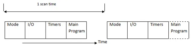
Where:
- Mode – Determines mode of operation (Run, Halt, etc.)
- I/O – Update and process all inputs and outputs
- Timer – Update all running timers
- Main Program – All logic blocks created under Main
The length of a scan is not deterministic. It depends on what blocks are executed, etc. If precise timing is required, use a timer interrupt routine.
Power Up Blocks
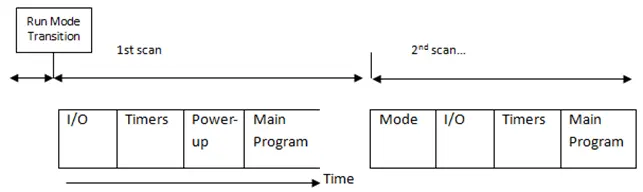
If Power Up blocks are present, they are executed once at the beginning of the first scan (before main block execution). Therefore, Power Up blocks can be used to set initial values into registers. The figure below shows the first scan operation.
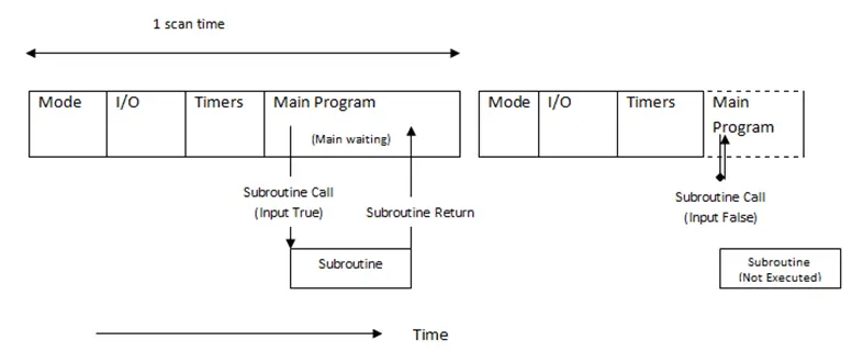
Subroutine Blocks
Subroutines are not executed unless specifically called by another logic block. Subroutines are useful when you have a set of commands that should be executed only under certain conditions. A maximum of 256 subroutines can be created (dependent upon total memory available).
Timer Interrupt Blocks
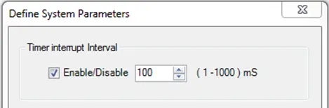
Timer interrupt logic blocks are given the highest priority when the MAPware-7000 program is executed. The timer interrupt is enabled by going to the Define > System Parameters dialog box and checking Timer Interrupt Interval.
When enabled, the timer interrupt routine is executed based upon the interval selected (range is 1-1000 milliseconds).
All other operations are suspended when the timer interrupt activates. Use this feature sparingly if you have a continuous operation that is time-critical. Because timer interrupt routines halt all other activities, to minimize its impact on the performance of the controller, design the interrupt routine to be as short as possible and adjust the timer interrupt interval to the maximum setting that still meets the requirements of your application.