
Creating a Sample Project using Native Ladder
Introduction
This first section will provide step by step instructions for creating a simple test project using the Native Ladder Logic editor. The project will display and manipulate digital inputs and outputs, as well as take a 16 bit analog input and scale it to a human readable engineering value. The value will also be checked against limits to determine if it’s within an acceptable range.
For this example, we will use the following items.
- HMC3102A-M
- HMC3-M0808Y0401T expansion module
- MAPware-7000 software running on a PC
- Micro USB configuration cable (PN 7431-0119)
- Simple test circuit attached to the I/O module to test the inputs and outputs configured in the project.
The instructions presented here should be general enough that they can be adapted for equipment on hand.
The project will demonstrate.
- Configuration of input and output channels
- Writing a simple Native Ladder logic block that controls I/O points
- Scaling an analog input
- Configuring a screen with objects that display HMC data
- Navigating between screens
Create a New Project
Starting a new project in MAPware-7000 is straightforward. After MAPware-7000 has started, it will display the opening screen. This screen displays a list of recent projects and offers the ability to either open an existing project or create a new one.
To create a new project:
- Click the New option under the Project category, or select Project > New from the menu bar.
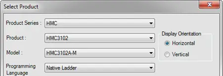
- When the Select Product dialog box appears, make the following selections:
- Product Series: HMC
- Product: HMC3102
- Model: HMC3102A-M
- Programming Language: Native Ladder
- Display Orientation: Horizontal
- Click OK. At this point, MAPware-7000 will give your project a default name based on the model number specified and open the Project Summary screen.
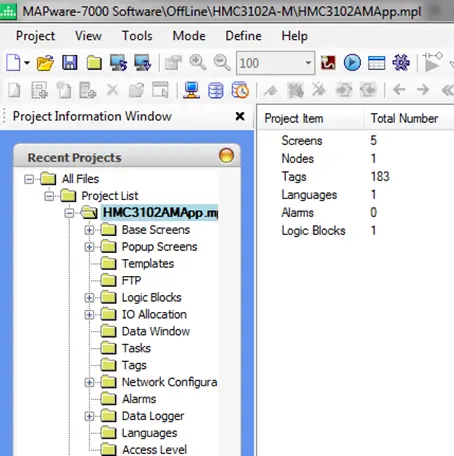
- To save the project with a new name, from the menu bar, select Project > Save.
- Select the directory where you want to store to project and enter a name for the project. We will use QuickStartExample for our project name.
- Click Save to save the new project.
Configure the I/O module
The first thing to set up in this new project is an I/O expansion module. This is done in the IO Allocation window.
- Expand the IO Allocation node in the Project Information Window, then click the Expansion folder.
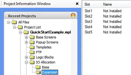
- The HMC3102A-M has five expansion slots, but we will only be using one of them. This is listed in the Main Workspace window, as shown above. Double click Slot1 in the list to open the IO Allocation window for this slot.
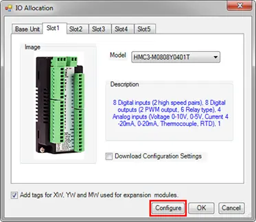
- In the IO Allocation window, select HMC3-M0808Y0401T from the Model dropdown.
- Click the Configure button at the bottom of this window to configure the channels we will use.
- Click the Analog tab.
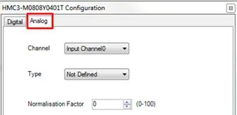
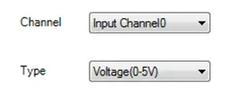
- We will use Input Channel 0 with a 0 to 5 V input range. Make sure Input Channel0 is selected in the Channel dropdown menu and select Voltage(0-5V) in the Type dropdown menu.
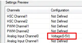
- Click Confirm to save this selection. Note that the selection now appears in the Settings Preview section at the bottom of the window.
- Click Close in the Configuration window. In the IO Allocation window, check the Download Configuration Settings checkbox.
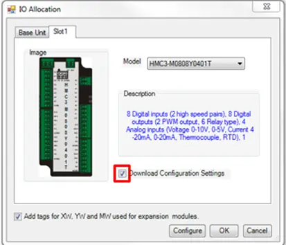
- Click OK in the IO Allocation window to complete the allocation.
Doing this adds the selected module to the project, allocates a set of I/O module tags in the tag database, and sets the default values of those tags according to the selected configuration.
For example, the settings above will create a tag called Slot01-CH0_Analog_IP_Type at address MW0160 and set the initial value of this tag to 6, which is the configuration register setting for the 0 to 5V input range. The raw input value can then be read from the tag named Slot01-CH0_AnalogIPReg at address XW0111.
For more information on I/O modules and associated tags, see the appropriate I/O Module Guide for your series of product.
Add Tags to the Project
Tags are names assigned to internal memory registers of the HMC, contacts of an expansion module, and any external PLC data registers/coils. Some system tags are predefined when you first begin a project. Other tags are created by the programmer. For example, you must create and assign a tag to every PLC memory address that you wish to read/write. When using the optional I/O Expansion modules, tags are created in order to use them. The Tag Database collects and stores all tags for review and editing.
Once a tag is assigned, you can easily link any object (i.e. bit lamp, numeric register, etc.) to the tag. Tags have several advantages.
- Tags provide an organized method of tracking all memory addresses used in a project.
- Tags are much more descriptive of functionality than the name of the memory address.
- Tags are easily edited, should a change be required.
- Tags can be exported and imported into other MAPware-7000 projects, regardless of which HMC/MLC unit is selected.
Once defined, the tag name can be used throughout the project to refer to a particular register, without needing to remember its memory address.
In Native Ladder projects, tags are defined to a specific address in the HMC’s memory. These addresses are grouped into different address spaces according to how a tag is intended to be used. Examples are; D-registers (general purpose data registers for 16- or 32-bit data), B-registers (single bit internal registers), and S/SW-registers (system tags that control how the HMC hardware functions).
In addition to the tags automatically generated for the I/O card, we will create custom tags to display values on the HMC screen and do calculations within Ladder Logic blocks.
- Click the Tags folder in the Project Information Window to open the Tag Database.
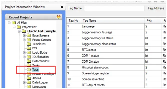
- To add a tag, right-click in the list of tags and select Add from the context menu, or click the Add Tag button up top.
- The Add Tag window is displayed. This window is used to configure the parameters for the new tag.
- Node Name – Specifies the device in which the tag is located. In this example, there is only one Node, the HMC3102A-M itself. If we had configured an external device in the Network Configuration window, such as another PLC, it would be available to select in this dropdown list.
- Tag-Name – Enter a descriptive name for the tag.
- Register/Coil Type – Pick a memory range to use for the tag.
- Tag-Type – Select between a Boolean two state tag (Coil or Bit addressed Register), or a Register tag (i.e. a byte, word or double word tag).
- Register – Memory address of the tag.
- Byte(s) – Specify the size of the tag (byte, word, or double word).
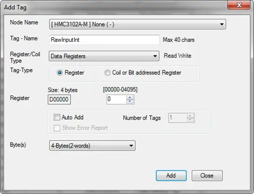
- We will add the following tags to the project using the Add Tag window.
| Name | Register / Coil Type | Register (address) | Byte(s) (length) | Description |
|---|---|---|---|---|
| RawInputInt | Data Registers | D00000 | 4-Bytes | Integer register to contain raw analog input |
| RawInputFloat | Data Registers | D00002 | 4-Bytes | Floating point format tag version of RawInputInt |
| RawLow | Data Registers | D00004 | 4-Bytes | Smallest possible value input register can have |
| RawHigh | Data Registers | D00006 | 4-Bytes | Largest possible value input register can contain |
| EngLow | Data Registers | D00008 | 4-Bytes | Smallest possible value of scaled input |
| EngHigh | Data Registers | D00010 | 4-Bytes | Largest possible value of scaled input |
| ScaledInput | Data Registers | D00012 | 4-Bytes | Scaled input value. |
| HighLimit | Data Registers | D00014 | 4-Bytes | High limit to test ScaledInput against |
| LowLimit | Data Registers | D00016 | 4-Bytes | Low limit to test ScaledInput against |
| DisableScaling | Internal Coils | B00000 | Coil | Disable (ON) / Enable(OFF) Scaling Logic |
| EnableLimits | Internal Coils | B00001 | Coil | Enable (ON) / Disable (OFF) limit logic |
- The Node Name is not modified, as there are no other nodes in our project and all tags are local.
- Type RawInputInt in the Tag-Name field and select Data Registers from the Register/Coil Type drop down.
- This first tag will be at Register 0, but for each following tag we will increment the address by 2, as each tag is 4 bytes (32 bits) long, and each Data Register is 2 bytes (16 bits) in length.
- Select 4-Bytes(2-words) from the Byte(s) dropdown menu.
- Click Add. The tag is added to the tag database, and the Add Tag window remains open.
- Change the Tag-Name to RawInputFloat and increment the Register by 2.
- Click Add again.
- Continue this process for the rest of the listed tags above. When adding the DisableScaling and EnableLimits tags, the Register/Coil Type must be changed to Internal Coils.
- Once all tags have been added, click the Close button. Any typos can be fixed by double-clicking on the tag to open the Edit Tag dialog box.
Initializing Tags with Power-On Tasks
To perform the scaling operation in this sample project, we need to initialize the tags used to define the input and output scales. There are two primary places available to perform initializations in MAPware-7000.
- In a Power-On Task
- In a Power Up Logic Block
We will use a set of Power-On Tasks. Tasks are specifically predefined actions taken by the controller, such as writing a value to a tag register, displaying a new screen, turning a bit on/off, etc. The number of tasks is limited only by the total amount of memory available in the controller. Each task has two fundamental components: the action taken when the task activates, and the triggering mechanism that starts the action.
- Click the Tasks folder in the Project Information Window to open the task editor.
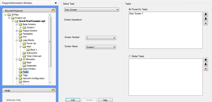
There are two Tasks sections in this window. Power-On Tasks are executed only once when the HMC first powers up. Global Tasks are executed continuously while the HMC is running. Notice that there is a default Power-On Task that tells the HMC which screen to display first.
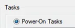
- Make sure the Power-On Tasks radio button is selected.
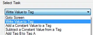
- From the Select Task dropdown list, select the Write Value to Tag task.
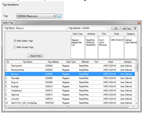
- In the Tag selection, choose RawLow from the dropdown or click the button to the right of the dropdown to open the Select Tag window.
- In the Number field, enter 0.

- Select Float from the Type dropdown list.
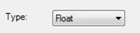
- Click the Add button. The task now appears in the Power-On Tasks list.
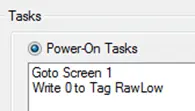
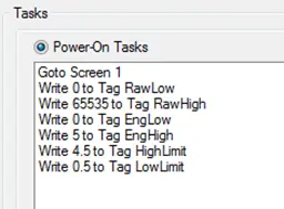
- Repeat this process to add Power-On Tasks that initialize the tags in the table below with the values shown. Make sure to set the Type to Float for each task.
| Tag | Value | Type | Notes |
|---|---|---|---|
| RawLow | 0 | Float | Minimum analog input value |
| RawHigh | 65535 | Float | Maximum analog input value (16 bit resolution) |
| EngLow | 0 | Float | Minimum scaled engineering value (0 Volts) |
| EngHigh | 5.0 | Float | Maximum scaled engineering value (5 Volts) |
| HighLimit | 4.5 | Float | Initial high limit |
| LowLimit | 0.5 | Float | Initial low limit |
- When complete, the list of Power-On Tasks should look like this.
Ladder Logic Blocks
With the tags defined and initialized, it is time to put them to use in a ladder logic program.
Scaling Analog Inputs
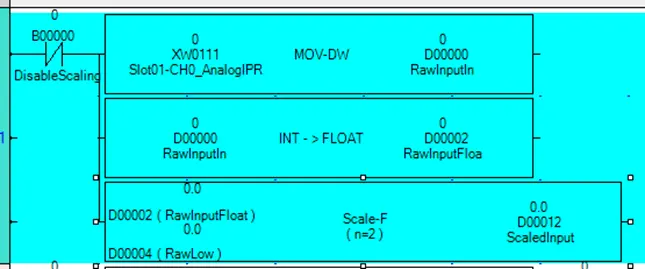
The first rung of the logic block will scale the raw input from Analog Input Channel 0 of the HMC3 M0808Y0401T I/O card to an engineering value of 0 to 5 volts. This is done by moving the raw input into a local tag, converting it to a floating point number, and then using the Scale instruction to scale the value.
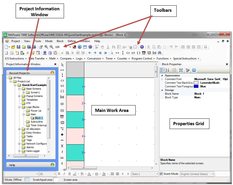
- Expand the Logic Blocks folder in the Project Information Window, then expand the Main folder.
- MAPware-7000 creates a default block in the Main folder called Block 1. Click the folder for this block to open the Ladder Logic editor.
- Select NC (Normally Closed) Contact from the I/O Instructions dropdown on the instruction menu, or click the icon on the Common Objects Toolbar. Then click directly to the left of the connection point for rung 1 to place the NC Contact.
- The Default operand selection window will open. Select the DisableScaling tag, then click OK. The button in the popup window will open the Select Tag window used in the previous section to help you find the required tag.
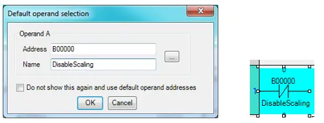
Note: Tag names are truncated by default to 6 characters in the logic editor window. To get the entire tag name to display, select Tools > Preferences > Project Global Settings from the menu bar and increase the Number of tag name characters to be displayed in Instruction setting to the maximum 20 characters.
This rung of logic can now be turned on and off with the DisableScaling tag. It will execute when DisableScaling is off, and be skipped if DisableScaling is on.
Because our engineering values represent voltages from 0 to 5 volts, we will need them to be floating point numbers. Before scaling, the raw input must be moved into a Data Register and converted to floating point format. To move the input value into a data register, use the Move DWord instruction.
For more information on the specific instructions used in the following steps, see the MAPware-7000 Ladder Logic Guide.
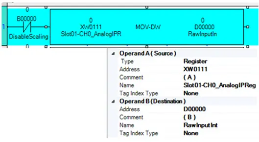
- Select Data Transfer > Move DW from the instruction menu, then click directly to the right of the Normally Open Contact to place the instruction. Select Slot01-CH0_AnalogIPReg as Operand A (Source), and RawInputInt as Operand B (Destination). This will move the 16-bit resolution raw analog input data into the tag we have created to work with the data.
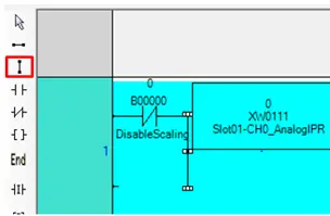
- Before placing the next instruction, we need to place a Vertical Link, also called a branch, after the contact and before the move instruction. Click the Vertical Link icon in the Common Objects Toolbar, then click between the NC Contact and the Move DWord instruction to place the Vertical Link.
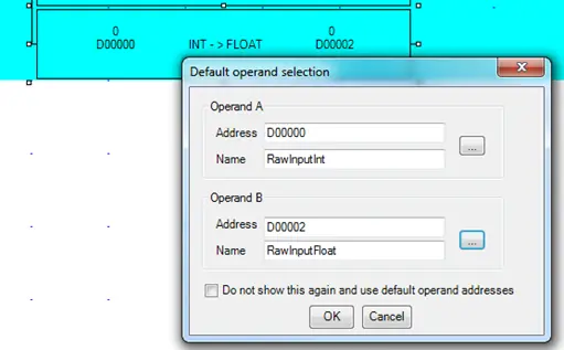
- To the right of this link, place an Integer to Float instruction (Conversion > Integer to Float from the instruction menu).
- Configure Operand A with the RawInputInt tag and Operand B with the RawInputFloat tag. As the name of the instruction implies, this will convert our raw input from an integer to a float.
- Another vertical link is required to add a third instruction below the Integer to Float instruction. Again, click the Vertical Link icon and then click immediately to the left of the Integer to Float instruction.
- To the right of this vertical link, place a Scale instruction (Functions -> Scale). Click OK to accept the default operand selection.
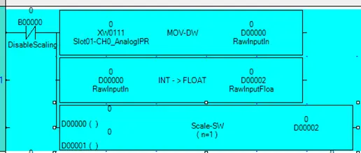
The Scale instruction has three operands. These are used to perform a linear mapping of the input (Operand A), to the output (Operand C). The figure below shows a graphic representation of the Scale instruction with two data points, n=2.
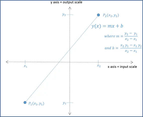
The input value x (Operand A) is mapped to an output value y(x) (Operand C) using the relationship shown. m and b, the slope and offset of y(x), are determined by four tags starting at the address specified in Operand B. These correspond, in consecutive order according to tag address, to the parameters. x1, x2, y1, y2, as shown in the figure.
- In the Instruction Properties panel, the Type property will need to be changed to Float. and the Data size property to 2 before selecting our tags. The Data size specifies the number of points to use in the linear mapping. This appears as n in the instruction.
- Operand A is the input, or x in the figure. For this operand use the output of the Integer to Float instruction (RawInputFloat).
- Operand B is the starting address of a block of four registers. The first of these registers defines the start of the input scale (the x coordinate of P1 in the figure), the second register defines the end of the input scale (the x coordinate of P2 in the figure), the third register defines the start of the output scale (the y coordinate of P1 in the figure), and the fourth register defines the end of the output scale (the y coordinate of P2 in the figure). Conveniently, we’ve already defined a block of four consecutive tags for this purpose, starting with the tag RawLow at address D00004.
| Tag Name | Register | Coordinate |
|---|---|---|
| RawLow | D00004 | x₁ |
| RawHigh | D00006 | x₂ |
| EngLow | D00008 | y₁ |
| EngHigh | D00010 | y₂ |
Select RawLow as Operand B.
- Operand C is the output, or y(x) in the figure. Select tag ScaledInput for Operand C.
You must change the instruction type to Float before assigning operands, because the instruction’s default type is a 2 byte integer. Attempting to select our previously created 4 byte float type tags before changing the instruction’s type to float will result in duplicate tags being created.
This completes the setup of the scaling operation. If scaling has not been disabled, this rung will copy the raw analog input into a local tag, convert the data into floating point number, and finally scale it from a raw 16 bit binary number (range from 0 to 65535) to an engineering value (from 0 to 5 volts).
Checking Output Limits
Next we will add the high and low limit logic to control two digital outputs that will indicate when the analog input is either too high or too low. This logic will be enabled or disabled using an enable bit (EnableLimits) in an input contact. If the output coil instructions were placed on the same rung as this enable contact, the outputs would be forced OFF whenever the enable bit is OFF. We would instead like the outputs to be free to toggle states even if EnableLimits is disabled. To accomplish this, the logic will be placed in a separate subroutine logic block, and the enable contact will be used to control whether or not the block is called (evaluated).
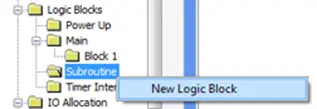
Create a new Subroutine logic block.
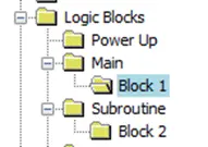
- Right-click the Subroutine folder and select New Logic Block from the context menu.
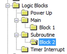
- Block 2 is created and a new editor window is opened.
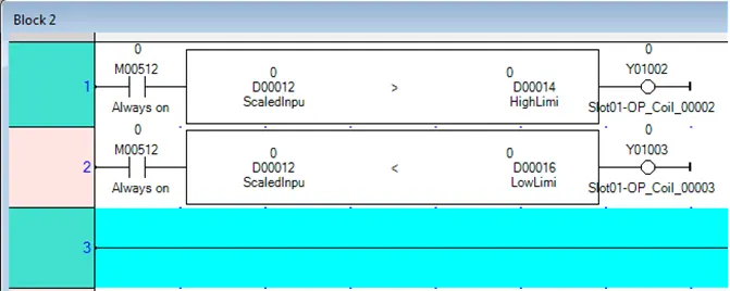
This subroutine will have two lines. One to check the high limit and one to check the low limit. The first rung will be used to check if the scaled input value is above the high limit.
- Click the NO Contact icon in the common objects toolbar, then click the input to rung 1 in the logic editor to place the contact.
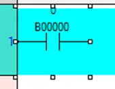
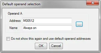
- Select the Always on (M00512) system bit. This bit is set on by the processor and will ensure that this rung always executes.
- Select the Greater Than instruction from the Instruction menu (Compare > Greater Than) and click to the right of the NO Contact. Click OK to accept the default operand selection.

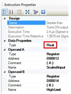
- The Type property for the Greater Than instruction will need to be changed to Float before assigning operands to ensure that duplicate tags are not created. Do this in the Instruction Properties grid.
- Then select ScaledInput for Operand A, and HighLimit for Operand B.
- If the ScaledInput value is above the high limit, the logic will set an output on the I/O card. A standard output coil instruction is used for this purpose. Click the Output icon in the Common Objects Toolbar.
- Click to the right of the Greater Than instruction to place the Output.

- Select Slot01-OP_Coil_00002 (Y01002) as the tag controlled by this output coil and click OK.
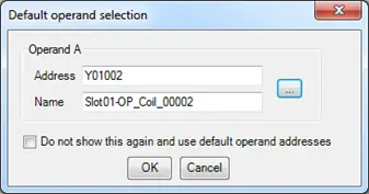
This is the coil controlling the first relay output on the I/O card (terminal Y2).
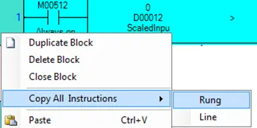
- To complete this subroutine, we just need to add the logic to test the lower limit. We will start rung 2 by making a copy of rung 1. Right-click to the left of the input on rung 1. From the context menu select Copy All Instructions > Rung.
- Right-click rung 2. From the context menu, select Paste. This will put a copy of the instructions from rung 1 on rung 2.
- Click the second Greater Than instruction to select it. Then right-click to delete it or press Delete on your keyboard.
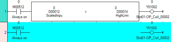
- Select a Less Than instruction (Compare > Less Than) to place in the open space and accept the default tags.
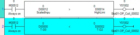
- In the Instruction Properties grid, set the Type property to Float, Operand A to ScaledInput, and Operand B to LowLimit.
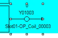
- Change the Output instruction coil address to Slot01-OP_Coil_00003 (Y01003).
- Because this logic block is a subroutine, it must end with a Subroutine Return instruction. From the instruction menu, select Program Control > Subroutine return.
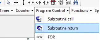
- Click anywhere on rung 3 to place the instruction.

This completes the logic for the subroutine logic block. The completed block should look like this:
- Finally, we must add a rung to Block1 that will call the subroutine. Click the folder for Block1 in the Project Information Window to reopen the Main Block 1 editor.
- Place an NO Contact on rung 2 that can be used to enable/disable the logic rung we are about to create.
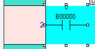
- Select EnableLimits to use as the tag for this contact and click OK in the tag selection window. This will allow this rung of logic to be turned on and off during runtime.
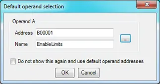
- Place a Subroutine call instruction (Program Control > Subroutine call) on the output of this contact.

Make sure that the Block Name property for the subroutine call instruction is set to Block 2.
This completes the logic needed for this sample project. The completed logic block (Block 1) should now look something like this.
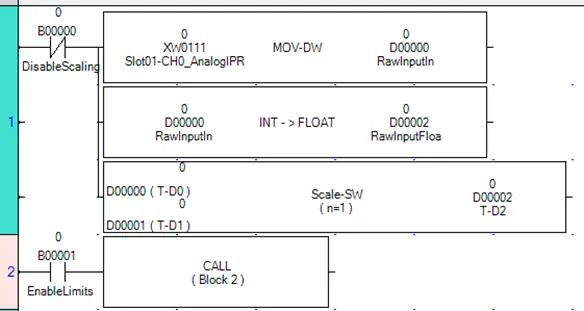
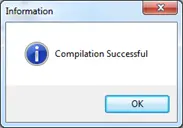
This is a good time to compile and save the project to make sure there are no errors. To do this, either click the compile icon, select Project > Compile, or hit F9. A successful compile will show a Compilation Successful message.
If there are any compile errors, they will be listed in the output window.
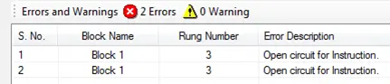
Fix any errors before moving on.
Create Screen Objects
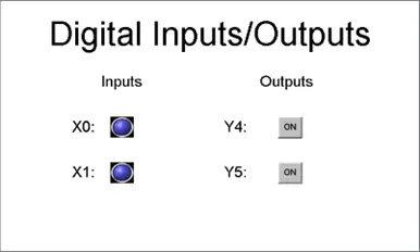
To see what the logic is doing in real time, we will create HMI screens to display information. The first screen will be used to display the digital I/O points. It will show the current state of input channels X0 and X1 and control the outputs Y4 and Y5
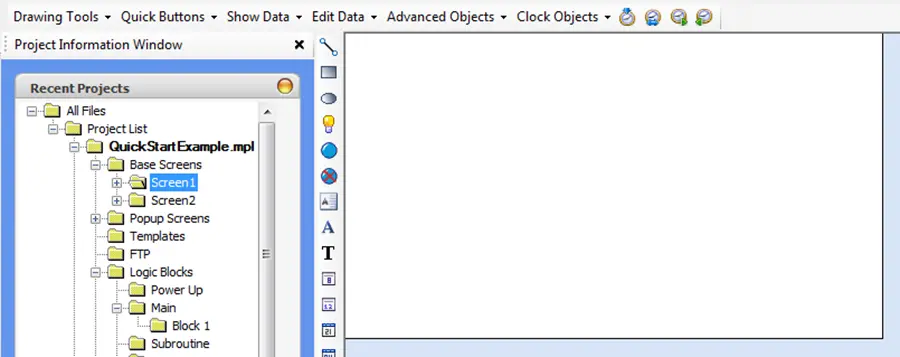
- In the Project Information Window, click to expand the Base Screens folder. By default, Screen1 is already present.
- Click the Screen1 subfolder to display the work area for Screen1.
Labels
Before adding data display objects to the screen, we will add labels so that it is clear what data the screen is displaying. There are two text objects in MAPware-7000 – Multilingual Text and Text. Multilingual Text uses Windows fonts and supports the Languages feature, which allows you to select up to nine languages. The Text object has more animation features, but fewer font options. We will use Multilingual Text objects for our labels.
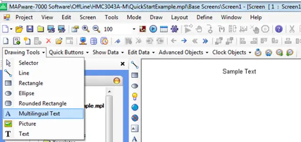
- Select Drawing Tools > Multilingual Text from the Draw menu, then click in the work area to place the Multilingual Text object.
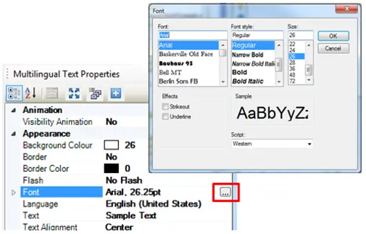
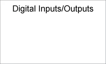
- This text will provide a title for the window. In the Properties grid, select the Font property and then click the ellipsis button to the right. Change the font size to 48 point.
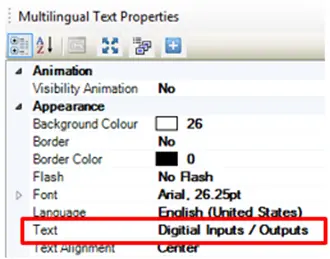
- Change the Text property from Sample Text to Digital Inputs/Outputs.
- Use the position boxes to expand the text object as needed to display the entire text. Use the Center along Screen’s Horizontal toolbar icon to center the title on the screen.
- Create a copy of this Multilingual Text object to use as a label for the input section. Right-click the object and select Copy from the context menu. Then right-click elsewhere on the screen and select Paste from the context menu. Click and drag the copy to a new location on the screen.
- Change the Font Size property to 22 point and the Text property to Inputs.
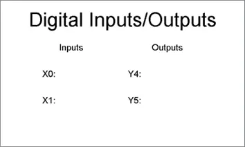
- Continue to make copies to create the following labels as shown [Inputs, Outputs, X0:, X1:, Y4:, and Y5:].
Bit Lamps
With the labels in place, we will now add bit lamps to monitor the state of the two inputs.
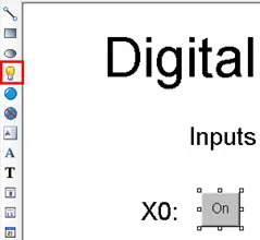
- Click the Bit Lamp icon, then click the screen to the right of the label for X0:.
- In the properties grid for this Bit Lamp, change the Style property to From Picture Library.
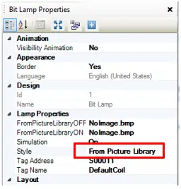
- Click the field for the FromPictureLibraryOFF property, then click the ellipsis button to open the library browser. Select any of the lamps, then click OK.
- Note: This will automatically select the corresponding ON image for the FromPictureLibraryON property.
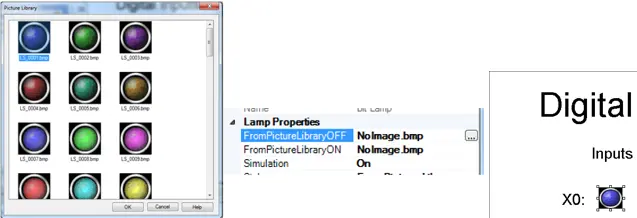
- In the Tag Name property for the Bit Lamp object, select Slot01-IN_Coil_00000 as the tag to use.

- Make a copy of this bit lamp and place it to the right of the X1: label.
- Change the Tag Name property of the new Bit Lamp object to Slot01-IN_Coil_00001.
Toggle Bit Objects
Next, we will add Toggle Bit objects to control two outputs.
- From the Draw toolbar select Advanced Objects > Buttons > Bit Action > Toggle Bit. Click to the right of the label for output Y4 to place the Toggle Bit button.
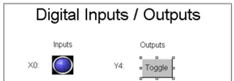
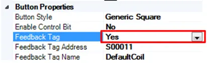
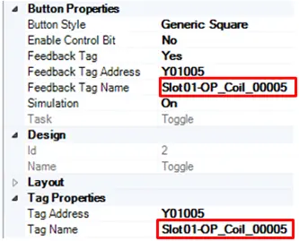
- In the properties grid for this Toggle Bit object, change the Feedback Tag property to Yes. This allows a tag to control the appearance of the Toggle Bit object on the screen. It can be set to the same tag that the object is controlling, or to a different tag.
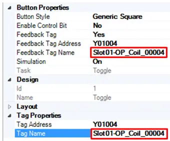
- Select Slot01-OP_Coil_00004 for both the Feedback Tag Name property and the Tag Name property.
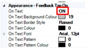
- In the Appearance – Feedback Tag On section, change the On Text property to ON.
- Make a copy of the Toggle Bit object and place it to the right of the Y5: label.
- In the properties for the new Toggle Bit object change both the Feedback Tag Name and Tag Name properties to Slot01-OP_Coil_00005.
- Use the alignment toolbar options to neaten up the screen.
Duplicating a Screen
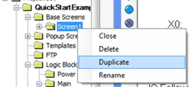
- Right-click the Screen1 folder in the Project Information Window and select Duplicate from the context menu.
- You should now see two screens listed in the project tree.
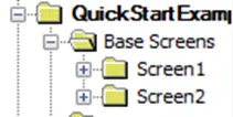
- The editor screen has changed to the new Screen2, even though it looks exactly the same as Screen1, because it is a duplicate.
- Before moving on to Screen2, we need to add a navigation button to Screen1 that opens Screen2. Click the Screen1 folder to switch back to the Screen1 editor window.
- From the Draw toolbar, select Quick Buttons > GoTo Screen.
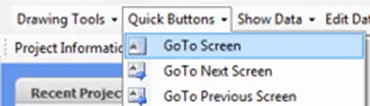
- Click in the lower right of the screen to place the navigation button.
- In the Property Grid for the GoTo Screen button, change the On Text property to Analog, and the Screen Name property to Screen 2.
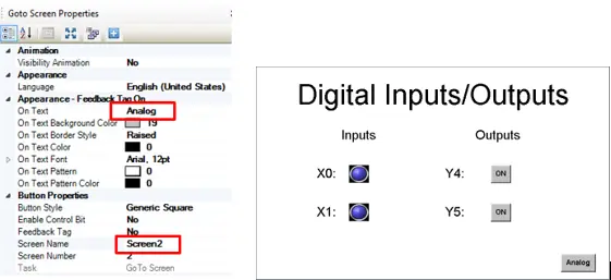
This completes Screen1. Screen2 will be used to monitor analog input channel 0, along with the scaling and limits functionality created earlier in the logic blocks.
- Click the Screen2 folder in the Project Information Window.
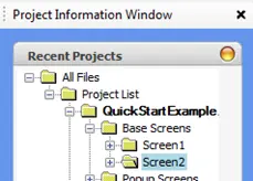
Screen2, looking exactly the same as Screen1 without the GoTo Screen button, will appear in the work area.
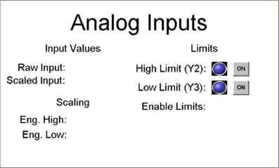
- To edit the text of an existing label, click the label to open its property grid. Then enter the desired text in the Text property. Edit the title of Screen2 so that it reads Analog Inputs.
- Change the Inputs label to Input Values, the X0: label to Raw Input:, the X1: label to Scaled Input:, the Outputs label to Limits, the Y4: label to High Limit (Y2):, and the Y5: label to Low Limit (Y3):. Adjust the size of the text objects as needed to display the full text.
- Copy and paste to create four more new labels. Set the text to Scaling, Eng. High:, Eng. Low:, and Enable Limits:.
- Move around your labels, Bit Lamps, and Toggle Bit objects to the approximate locations shown below.
Numeric Displays
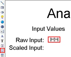
- From the Common Objects toolbar, click the Numeric Display icon, then click to the right of the Raw Input: label.
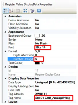
- In the properties grid for this Numeric Display object, set the Font property to 10 x 14 and the Tag Name property to Slot01-Ch0_AnalogIPReg. In the Format section, change the Number Of Digits to 5.
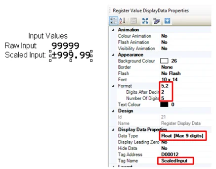
- Create a copy of this Numeric Display object and paste it directly below to use as the Scaled Input: display.
- In the properties grid for the Scaled Input: numeric display, change the Format > Digits After Decimal property to 2, the Data Type property to Float, and the Tag Name property to ScaledInput.
Numeric Entry
Next we will place two Numeric Entry objects next to the Eng. High: and Eng. Low: labels. The Numeric Display object simply displays a register value. The Numeric Entry object displays a register value and allows the user to modify the register value. These two Numeric Entry objects will allow the user to modify the engineering scale during runtime.
- From the Common Objects toolbar, click the Numeric Entry icon, then click to the right of the Eng. High: label.
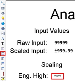
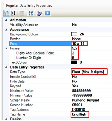
- In the properties grid for the Numeric Entry object, set the Font property to 10 x 14, the Tag Name to EngHigh, the Data Type to Float, the Format > Number Of Digits to 5, and the Format > Digits After Decimal Point to 2.
- Create a copy of this Numeric Input object and paste it directly below the original to create a Numeric Input for EngLow:. Change the Tag Name property from EngHigh to EngLow.
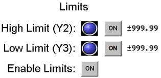
The last section of Screen2 will display the limit indicators controlled by the ladder logic program. The existing Bit Lamp and Toggle Bit objects will be modified for this section. Two Numeric Entry objects will be added, allowing the limits to be adjusted.
- Change the Tag Name property for the HighLimit bit lamp from Slot01-IN_Coil_00000 to Slot01-OP_Coil_00002. Change the Tag Name and Feedback Tag Name properties for the HighLimit toggle switch from Slot01-OP_Coil_00004 to Slot01-OP_Coil_00002 as well.
- Change the Tag Name property in the LowLimit bit lamp from Slot01-IN_Coil_00001 to Slot01-OP_Coil_00003. Change the Tag Name and Feedback Tag Name properties for the LowLimit toggle switch from Slot01-OP_Coil_00005 to Slot01-OP_Coil_00003.
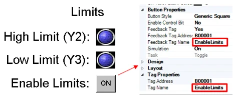
- Copy and paste one of the toggle bit objects and place it next to the Enable Limits: label.
- Change both the Feedback Tag Name and Tag Name properties in the Enable Limits: toggle bit object to EnableLimits.
- Create a copy of the Eng. High: Numeric Entry object and paste it to the right of the High Limit (Y2): Toggle Button object. Change the Tag Name property in this new Numeric Entry object from EngHigh to HighLimit. Repeat to create a LowLimit Numeric Entry object.
- To complete the second screen, add a GoTo Screen button allowing the operator to navigate back to Screen1. Select Quick Buttons > GoTo Screen from the Draw toolbar. Click in the lower right corner of the screen to place the button.
- In the property grid for the new button, set the On Text property to Digital and the Screen Name property to Screen1.
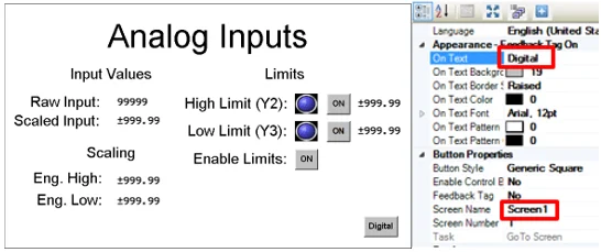
This completes the set up for the second screen. Save and Compile to check for errors. The project is now complete and ready to be downloaded to the HMC hardware.
Testing the Project
Test Hardware Setup
Install the HMC3-M0808Y0401T expansion module into the expansion slot of the HMC3102A-M. Connect the HMC3102A-M to a 24VDC power supply. Connect the 0 and 24VDC connectors on the HMC3-M0808Y0401T to the 24VDC power supply.
A simple test circuit to control the inputs and view the outputs is shown below.
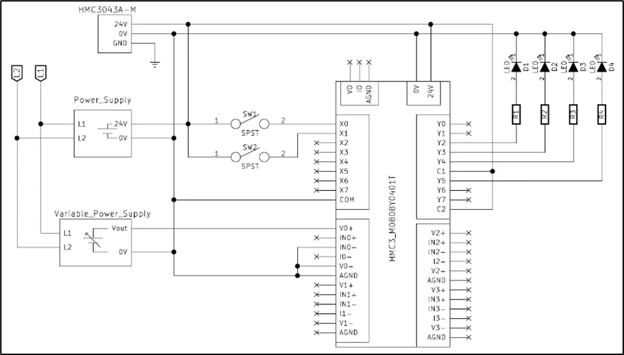
If indicator LEDs or lamps are not available, the continuity function on a digital multi-Meter can be used to test the state of the relay outputs. For outputs Y2, Y3, and Y4, test continuity between C1 and the output pin. For output Y5 test continuity between C2 and Y5. Do not connect 24V to C1 and C2 in this case.
Downloading the Project
This step assumes that you are using a USB download cable. You may also download to the HMC via Ethernet, but additional steps are required to ensure that your computer and HMC are on the same IP Subnet.
See the MAPware-7000 Programming Manual for more detail on downloading via Ethernet.
- Connect a Micro USB download cable (PN. 7431-0019) between your programming computer and the HMC USB Slave Port.
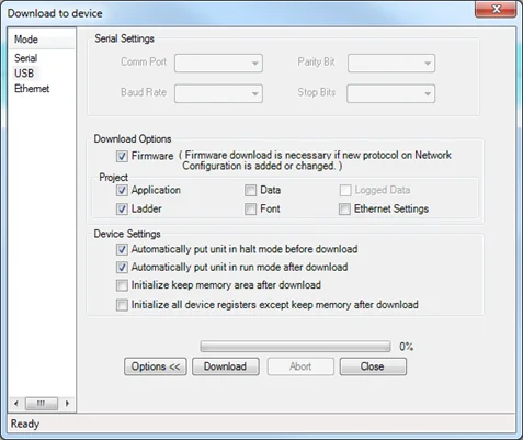
- Click Project > Transfer > Download to display the Download to device dialog box.
- Under Download Options, check Firmware.
- Under Project, check Application and Ladder.
- Under Device Settings, check Automatically put unit in halt mode and Automatically put unit in run mode.
- Click the Download button.
Note: You can check the Do not show this message again box to hide this warning message on future downloads during the current session.
- Click OK. The file will begin downloading.
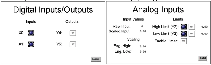
- When complete, the HMC3102A-M will reinitialize and display the application.
Running the Application
Application test procedure:
- Toggle the output toggle bit buttons. Verify the corresponding outputs come on.
- The bit lamp indicators should change state when the corresponding input switch is closed.
- On the analog screen, vary the input voltage and watch the raw and scaled values change.
- Enable the High/Low limits and vary the input voltage to see Y2 and Y3 toggle on and off at each limit.
- Verify the toggle switches for Y2 & Y3 work when the Enable Limits toggle is off, and do nothing when the Enable Limits toggle is on.
- Touch the High and Low limit numeric entry objects to change the values on the fly and verify that Y2 and Y3 toggle on and off at the new limits.
- Do the same for the Eng. High and Eng. Low to change the output scale of the scaling instruction.
Online Monitoring
The HMI screen provides a window into what is happening in the HMC; however, for a complicated project with many logic blocks, it is often not enough to debug the logic. Online Monitoring allows the programmer to view the logic in real time, and modify data directly in logic blocks. With the project running in the HMC and the USB download cable still attached, MAPware-7000 can be used to monitor logic block execution in real time.
- Open the editor for Block 1
- Select Tools > Preferences > Online Communications Mode to select the communication method used for online monitoring.
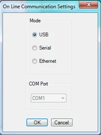
Note: For Ethernet mode, the IP address of the device must be entered in this window. The IP address here should match what is configured on the Ethernet tab of the Project Properties dialog. The address of the device is only updated when the Ethernet Settings box is checked in the Download window. The current IP address is shown on the HMI screen when the device is booting up. Here we assume USB is selected.
There are three options for initiating an online monitoring session.
- With Download – The currently open project will be downloaded to the device before the online monitoring session begins.
- Without Upload – The online session will begin with the project that is open and with the project that is in the device. This assumes that the currently open project is the same as the project on the device.
- With Upload – The currently open project will be closed. The project on the device is uploaded and opened, before the online session begins. This is the only option available when no project is opened.
These options are available by selecting Mode > Go Online from the menu. Note. clicking the online icon is equivalent to selecting Without Upload form the Go Online menu option.
- Because we already have our project open, select Mode > Online > Without Upload from the menu bar.
The logic block will be shown with the current values above the operands.
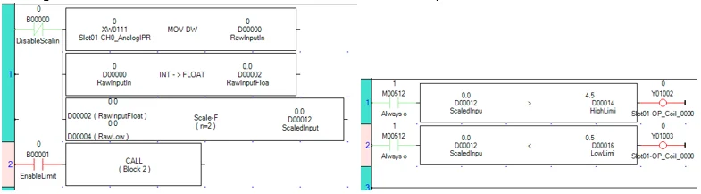
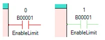
Contacts and coils are color coded according to their current state. Contacts are red when open (off), and green when closed (on).
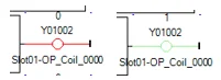
Output coils are green when energized (on), and red when not energized (off).
Values can be changed from within the logic block editor. Double click the contact or operand to be changed, then enter the state or value as needed.
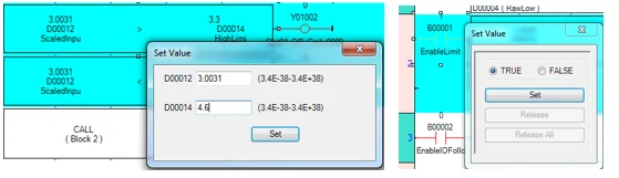
For more information on using online monitoring or debugger mode, refer the MAPware-7000 Ladder Logic Guide.
Review
Before moving on to IEC 61131-3 programming, let’s review what has been learned in this section. Consider what has been accomplished:
- A new project was created and configured for an HMC model, including setting up and configuring an expansion module.
- The tag database was used to create new tags using internal HMC memory as well as I/O module registers.
- Two screens were created using data display, data entry, and navigation objects.
- The project showed how to create a simple ladder logic program using Logic Blocks, including a subroutine block.
- The project was saved, compiled, and downloaded into the HMC.
- Online monitoring mode was used to view the application as it executed.
The next section of this guide will explore the IEC 61131-3 programming environment.