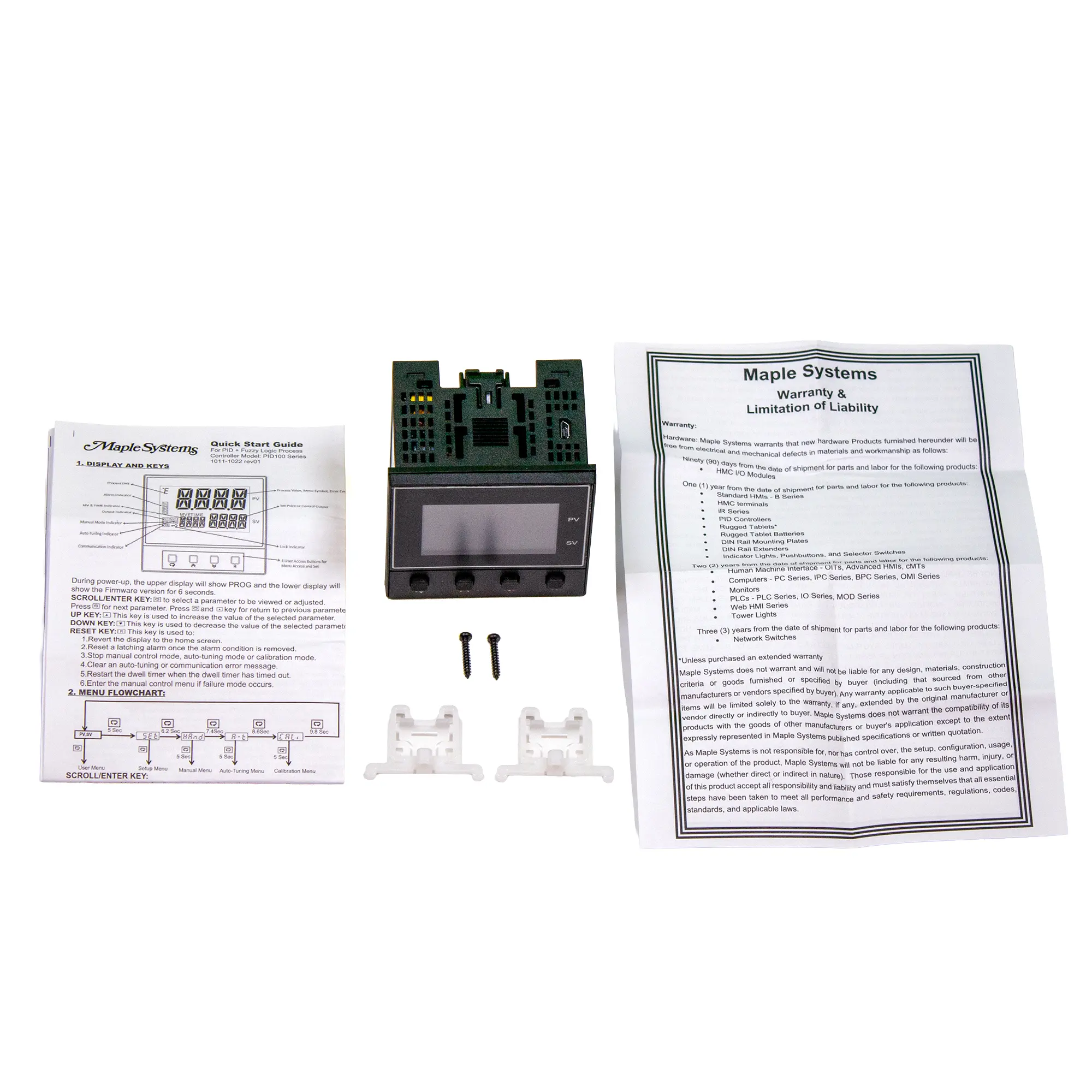
PID Temperature Controller, 20-28VAC/11-40VDC, 9/64 DIN, CT Input, Data Communications, Remote Setpoint
$185.00
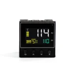
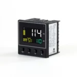
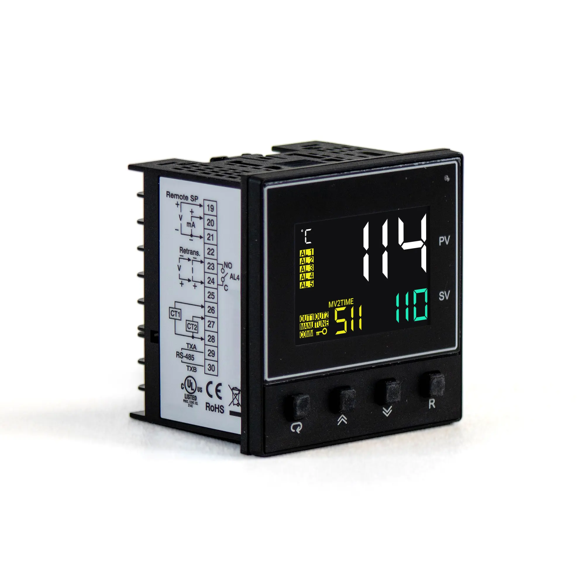
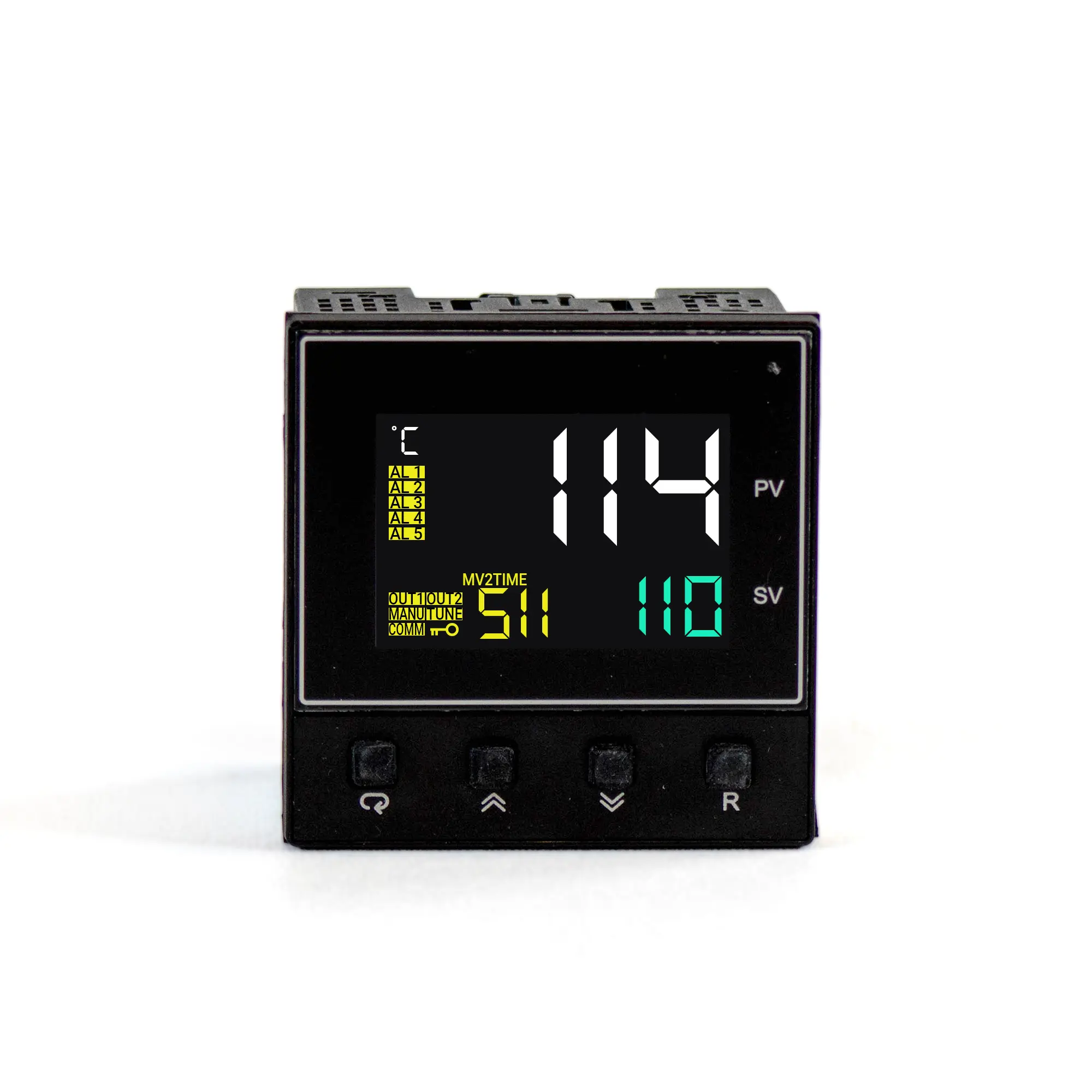
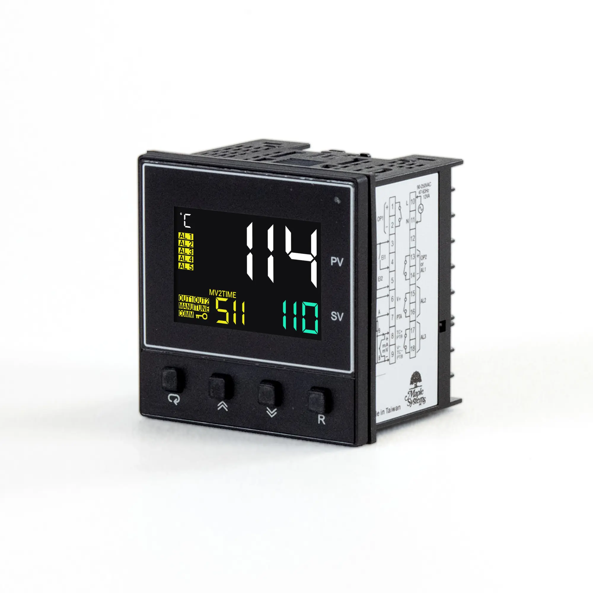
The PID114-51110110 is a high-performance process and temperature controller with fuzzy logic, auto tuning, universal inputs, dual PID control, and built-in heater break detection. Its 2.8″ x 2.8″ panel mount design, precise 18-bit inputs, fast sampling, and Modbus RTU communications make it ideal for demanding industrial temperature and process control applications.
- US-based technical support.
Share the product:
- Dual Heating and Cooling Control
- Fuzzy PID Control & Autotuning
- Universal Thermocouple, RTD, mA, and Voltage Inputs
- 18-bit Resolution
- Fast 200ms Sampling
- Remote Set Point Option
- Built-in Modbus RTU
- CT Input
- Compact 9/64 DIN Panel Mount
- 20 to 28 VAC, 47-63 Hz / 11 to 40 VDC
Power Details
| Power Supply | 20 to 28 VAC, 47-63 Hz / 11 to 40 VDC |
|---|---|
| Power Consumption | 12VA, 6 W Maximum |
| Over Voltage Category | II |
Signal Input
| Type | Thermocouple (J, K, T, E, B, R, S, N, L, U, P, C, D), RTD(PT100(DIN), PT100(JIS)), Current(mA), Voltage (V, mV) |
|---|---|
| Resolution | 18 bits |
| Sampling Rate | 5 Times / Second (200 msec) |
| Maximum Rating | -2V DC minimum, 12 VDC maximum |
| Temperature Effect | ±1.5 µV /°C for all inputs except mA input, ±3.0 µV /°C for mA |
| Sensor Lead Resistance Effect | Thermocouple: 0.2 µV /°Ω 3-wire RTD: 2.6 °C /Ω of Difference of Resistance of two leads 2-wire RTD: 2.6 °C /Ω of Sum of Resistance of two leads |
| Burn-out Current | 200 nA |
| CMRR | 120 dB |
| NMRR | 55 dB |
| Sensor Break Detection | Sensor open for: Thermocouple, RTD, and mV inputs Sensor short for: RTD Input Below 1mA for: 4-20mA input Below 0.25 VDC for: 1-5 VDC input Not available for other inputs |
| Sensor Break Response Time | Within 4 seconds for: Thermocouple, RTD, and mV inputs Within 0.1 seconds for: 4-20mA and 1-5 VDC inputs |
Remote Set Point Input
| Type | Linear Current, Linear Voltage |
|---|---|
| Range | -3mA to 27 mA, -1.3 VDC to 11.5 VDC |
| Accuracy | ±0.05% |
| Remote Set Point Option | Available |
| Input Impedance | Current: 2.5 Ω, Voltage: 1.5 MΩ |
| Resolution | 18 Bits |
| Sampling Rate | 1.66 Times/Second |
| Maximum Rating | 280 mA maximum for Current Input, 12 VDC Maximum for Voltage Input |
| Temperature Effect | ±1.5 µV/°C for Voltage Input, ±3.0 µV/°C for Current Input |
| Sensor Break Detection | Below 1mA for 4-20 mA input Below 0.25 VDC for 1-5 VDC input Not available for other inputs |
| Sensor Break Response Time | 0.1 Second |
CT Input
| Accuracy | ±5% of Full-scale Reading ±1 Digit |
|---|---|
| Input Impedance | 294 Ω |
| Measurement Range | 0 to 50 AAC |
| Output of CT | 0 to 5 VDC |
| Sampling Rate | 1 Time/Second |
Output 1/ Output 2
| Type | Relay, Pulsed Voltage, Linear Voltage, or Linear Current |
|---|---|
| Relay Routing | 2A,240 VAC, 200000 Life Cycles for Resistive Load |
| Pulsed Voltage | Source Voltage 5 VDC, Current Limiting Resistance 66 Ω |
| Linear Output Resolution | 15 Bits |
| Linear Output Regulation | 0.02% for full load change |
| Linear Output Setting Time | 0.1 Sec (Stable to 99.9%) |
| Linear Output Ranges | 0-22.2 mA (0-20 mA/4-20 mA), 0-5.55 VDC (0-5 VDC, 1-5 VDC), 0-11.1 VDC (0 – 10 VDC) |
| Isolation Breakdown Voltage | 1000 VAC |
| Temperature Effect | ±0.01% of Span/ °C |
| Load Capacity of Linear Output | Linear Current: 500Ω max., Linear Voltage: 10 KΩ min |
Alarm
| Relay Type | Form A |
|---|---|
| Maximum Rating | 2A, 240 VAC, 200000 Life Cycles for Resistive Load |
| Alarm Functions | Dwell Timer, Deviation Low, Deviation High, Deviation In-Band, Deviation Out of Band, Process High, Process Low, Range High, Range Low, Range High Low Profile Hold Back, Profile end, Heater Break, Heater Short, Event Input 1 & Event Input 2 controlled alarm Output |
| Alarm Mode | Latching, Hold, Normal, Latching/Hold, Setpoint Holding, Latching None Reset |
| Dwell Timer | 0.1 to 4553.6 Minutes |
Data Communication
| Interface | RS-485 |
|---|---|
| Protocol | Modbus RTU (Slave Mode) |
| Address | 1 to 247 |
| Baud Rate | 2.8 KBPS to 115.2 KBPS |
| Parity Bit | None, Even, or Odd |
| Stop Bit | 1 or 2 Bits |
| Data Length | 7 or 8 Bits |
| Communication Buffer | 160 Bytes |
Analog Retransmission
| Output Signal | N/A |
|---|---|
| Resolution | N/A |
| Accuracy | N/A |
| Load Resistance | N/A |
| Output Regulation | N/A |
| Output Setting Time | N/A |
| Isolation Breakdown | N/A |
| Integral Linearity Error | N/A |
| Temperature Effect | N/A |
| Saturation Low | N/A |
| Saturation High | N/A |
| Linear Output Ranges | N/A |
User Interface
| Keypad | 4 Keys |
|---|---|
| Display Type | 4 Digit LCD Display |
| No. of Displays | 3 |
| Upper Display Size | 0.58” (15 mm) |
| Lower Display Size | 0.32” (8.3 mm) |
Programming Port
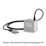
| Interface | Micro USB |
|---|---|
| PC Communication Function | Firmware upgrade |
Control Mode
| Output 1 | Reverse (Heating) or Direct (Cooling) Action |
|---|---|
| Output 2 | PID cooling control, Cooling P band 50~300% of PB, Dead band -36.0 ~ 36.0% of PB |
| ON-OFF | 0.1~50.0 °C (0.1~90.0 °F) hysteresis control (P band = 0) |
| P or PID | 0 – 100.0% offset adjustment |
| PID | Fuzzy logic modified Proportional band 0.1 ~ 500.0 °C (0.1~900.0 °F), Integral time 0 – 3600 Secs, Derivative Time 0 – 360.0 Secs |
| Cycle Time | 0.1 to 90.0 Seconds |
| Manual Control | Heat (MV1) and Cool (MV2) |
| Auto-Tuning | Cold Start and Warm Start |
| Failure Mode | Auto transfer to manual mode while sensor break or A-D Converter damage |
| Ramping Control | 0 to 500.0 °C (0 to 900.0 °F)/Minute or 0 to 500.0 °C (0 to 900.0 °F)/Hour Ramp Rate |
Digital Filter
| Function | First Order |
|---|---|
| Time Constant | 0, 0.2, 0.5, 1, 2, 5, 10, 20, 30, 60 Seconds, Programmable |
Mechanical
| Dimensions WxHxD | 2.8 x 2.8 x 2.3” [72 x 72 x 59mm] |
|---|---|
| Panel Cutout (inches) [mm] | 2.63 x 2.63” [66.8 x 66.8mm] |
| Weight | 0.42 lbs [190g] |
| Mounting | Panel mount |
| Construction | Flame Retardant Polycarbonate |
| DIN Size | 9/64 |
| Depth Behind Panel | 1.97” [50mm] |
Environmental
| Shock Resistance | 200 m/s2 (20g) |
|---|---|
| Vibration Resistance | 10 to 55 Hz, 10 m/s2 for 2 Hours |
| Altitude (Air Pressure) | Up to 2,000 Meters (~80 kPa) |
| Operating Temperature | 14° ~ 122°F (-10° ~ 50°C) |
| Storage Temperature | -40°F~140°F (-40°C~60°C) |
| Humidity | 0 to 90% RH (Non-Condensing) |
| Certifications | CE/ RoHS/ cULus/ REACH |
| Pollution | Degree II |
| Insulation Resistance | 20 MΩ Minimum (@500 VDC) |
| Dielectric Strength | 2000 VAC, 50/60 Hz for 1 Minute |
| EMC | EN61326 |
| Protective Class | IP50 front panel, IP20 rear terminals & housing. Indoor use. |
How do you tune a PID controller?
Start with auto-tuning if your controller supports it, or tune manually by adjusting proportional gain, the integral term, and the derivative term while watching the system response. Classic methods include the Ziegler-Nichols method, the Cohen-Coon method, and the relay method.
Products:
Manuals and Guides:
Technical Articles:
What is the difference between PI and PID control?
PI control uses proportional and integral terms to correct error and eliminate steady-state error. PID control adds derivative action, which responds to the rate of change of error to help reduce overshoot and improve stability. However, derivative action can amplify measurement noise and is not beneficial for every process.
Products:
Manuals and Guides:
Technical Articles:
How does a PID controller work?
A PID controller compares the process variable (the measured value) to the set point (the desired value) to calculate the error. It then uses proportional, integral, and derivative calculations to determine the appropriate control output. This signal adjusts a control element, such as a valve or motor, while sensor feedback allows the controller to continuously monitor the process and correct deviations from the set point.
Products:
Manuals and Guides:
Technical Articles:
What certifications do the PID100 series controllers have?
Maple Systems PID100 Series controllers are CE certified, cULus listed, and comply with RoHS and REACH requirements. They also meet EMC standard EN61326:
Certification: cULus
Compliance: RoHS and REACH
EMC: EN61326
Front panel protection: IP50
Rear terminal and housing protection: IP20
PID100 Series controllers are designed for indoor use and have an operating temperature range of 14°F to 122°F (-10°C to 50°C).
Products:
Manuals and Guides:
Technical Articles:
Do the PID100s support Modbus communications?
Yes, select Maple Systems PID100 Series controllers include built-in RS-485 communication and support Modbus RTU in slave mode.
Communication settings include:
Device addresses: 1 to 247
Baud rate: Configurable
Parity: None, even. or odd
Stop bits: One or two
Data length: Seven or eight bits
This allows the PID controller to exchange process and control data with compatible industrial automation equipment using Modbus RTU.
Products:
Manuals and Guides:
Technical Articles:
What is the difference between PID111 and PID114?
PID111s and PID114s are part of the Maple Systems PID100 Series and support universal inputs, fuzzy logic PID control, auto-tuning, flexible control outputs, and Modbus RTU communication.
The main differences are size and available features:
PID111: Compact 1/32 DIN controller with two 4-digit displays
PID114: Larger 9/64 DIN controller with three 4-digit displays
Heater break detection: Available on PID114s through a CT input
Remote set point input: Available as an option on PID114s
Panel cutout: PID111 uses a 45 x 22.2 mm cutout, while PID114 uses a 68 x 68 mm cutout
Choose the PID111s when panel space is limited and the additional PID114 features are not required. Choose the PID114 when your application needs heater monitoring, remote set point capability, or the larger display format.
Products:
Manuals and Guides:
Technical Articles:
What sensors work with the PID100 Series?
The Maple Systems PID100 Series support multiple sensors and process input types for PID temperature and process control applications.
Supported inputs include:
Thermocouples: J, K, T, E, B, R, S, N, L, U, P, C, and D
RTD: PT100 DIN and PT100 JIS
Current inputs: Current process signals, including 4-20 mA
Voltage inputs: Voltage and millivolt signals
The PID100 Series also includes sensor break detection for supported thermocouple, RTD, millivolt, current, and voltage inputs.
Products:
Manuals and Guides:
Technical Articles:
What is the panel cutout size for a PID114?
The PID114 is a 9/64 DIN panel-mount PID Controller.
For Installation:
Panel cutout: 68 x 68 mm
Controller dimensions: 72 x 72 x 59 mm
Depth behind panel: Approximately 50 mm
Recommended panel thickness: 1 to 5 mm
Always verify the current product datasheet before machining the panel opening.
Products:
Manuals and Guides:
Technical Articles:
What is the panel cutout size for a PID111?
For Installation:
Panel cutout: 1.77 x 0.88″
Controller dimensions: 1.89 x 0.95 x 3.6″
Depth behind panel: Approximately 84 mm
Always verify the current product datasheet before machining the panel opening.
Products:
Manuals and Guides:
Technical Articles:
When you order the PID114-51110110 the following items are included in the box:
- PID114-51110110
- Mounting Adapter
- Quick Start Guide
- Warranty Statement