
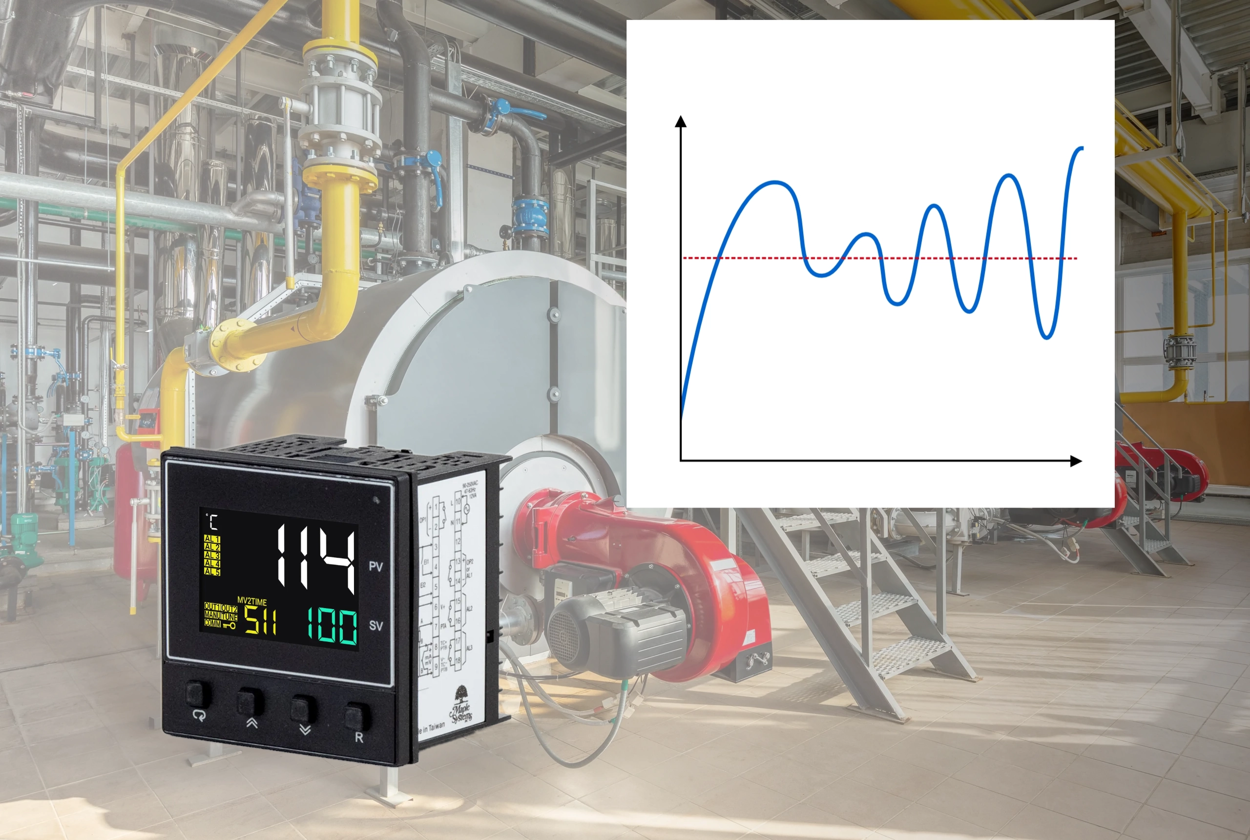
Imagine a heating tank that repeatedly rises above and falls below its temperature setpoint (SP). An operator adjusts the PID control loop settings, but the cycling continues. Is the controller responding too aggressively, is the temperature measurement delayed, or is the heating equipment failing to respond as expected?
PID loop troubleshooting starts with identifying which part of the control system is causing the problem. Incorrect tuning, measurement problems, actuator limitations, and changing process conditions can produce similar symptoms. This article explains how to compare those symptoms with operating data, narrow the possible causes, and choose an appropriate corrective action.
What Causes PID Loop Instability?
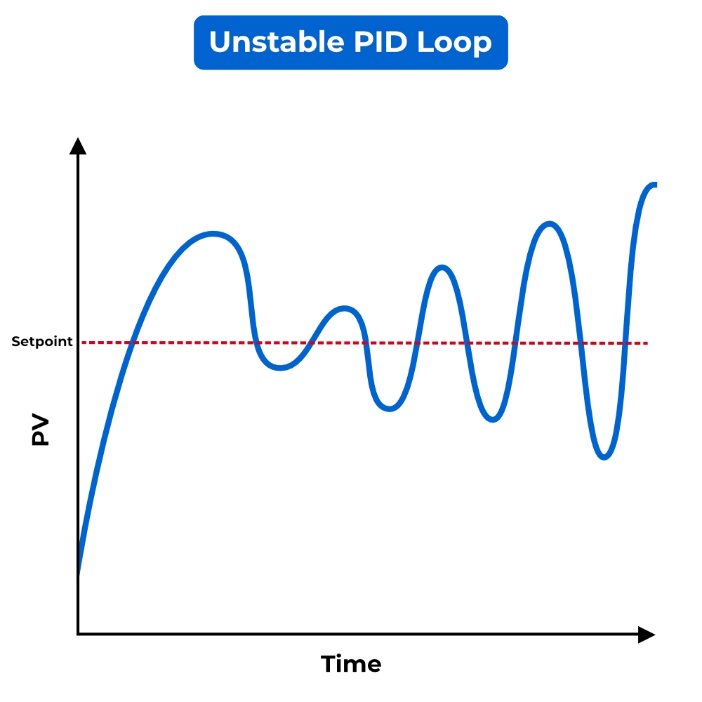
Poor PID control loop performance often appears as overshoot, oscillation, or hunting. Overshoot occurs when the process variable (PV) passes beyond its target after a change. Oscillation is repeated variation in a signal, while hunting describes repeated corrective movement as the controller or actuator searches for the desired operating point.
These symptoms alone don’t necessarily establish whether the loop is unstable or identify the underlying cause. A stable loop may overshoot or oscillate briefly before settling. Persistent cycling, growing oscillations, or repeated actuator movement require closer investigation. Incorrect tuning is one possible explanation, but measurement problems, actuator behavior, and process disturbances can produce similar results.
Aggressive or Incorrect PID Tuning
PID settings determine how strongly the controller responds to an error, how it corrects accumulated error, and how it responds to rapid changes. When these settings do not suit the process, the controller can overcorrect or react to fluctuations that do not represent meaningful process changes.
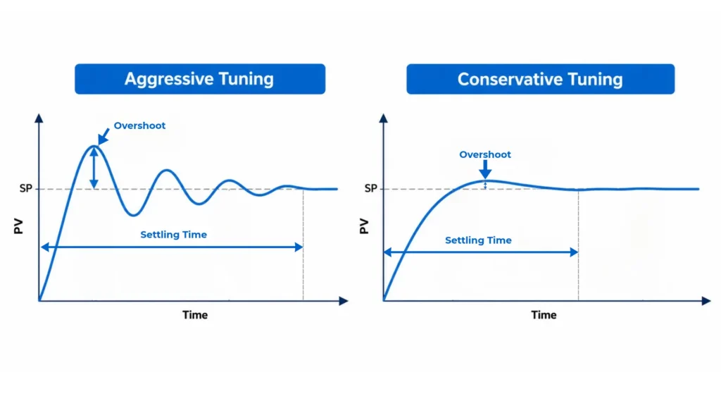
Excessive proportional gain can make small errors produce large output adjustments, contributing to overshoot and repeated corrections. Overly aggressive integral action can push the output too far before the process has time to respond. Derivative action can also make the output erratic when it responds to measurement noise. Once measurement and actuator problems have been ruled out, compare appropriate PID tuning methods to match the controller’s response to the process.
Sensor Noise, Measurement Problems, and Process Changes
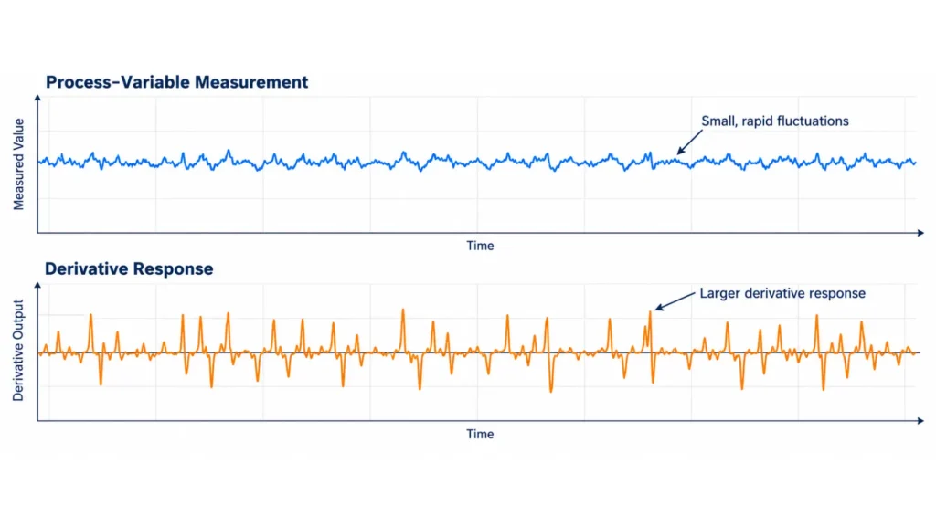
Before changing PID settings, verify that the feedback accurately represents the process. A poorly positioned sensor, intermittent wiring, incorrect scaling, or electrical interference can cause the controller to act on misleading measurements. Measurement noise can also produce rapid output fluctuations, particularly when derivative action is active.
Even accurate feedback may arrive too late for the existing tuning. A slower sensor response, changed sensor location, or increased process delay can cause the controller to continue correcting before the effects of earlier output changes becomes visible. Changes in flow, material properties, or operating load can also alter how the process responds.
Correct measurement faults before adding filtering. A filter can smooth noisy feedback, but it also adds lag and may require a review of the tuning. Our guide to signal conditioning and noise filtering explains these tradeoffs.
Actuator Saturation, Stiction, and Integral Windup
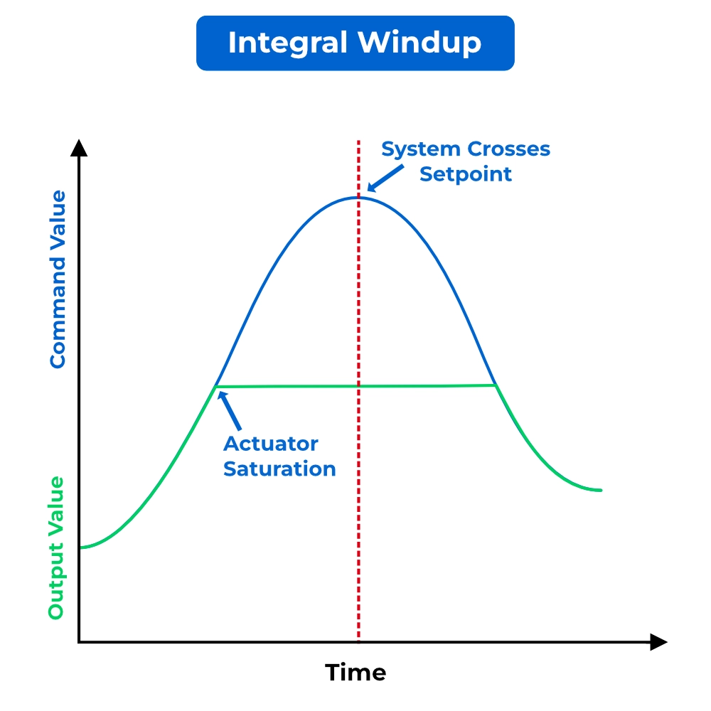
A controller can request a correction that the connected equipment cannot deliver. Saturation occurs when an actuator reaches a limit: a heater already operating at full power cannot supply additional heat, even if the temperature remains below the setpoint.
Mechanical problems can also prevent the requested response. Stiction occurs when static friction holds a valve in place until enough force builds to move it, sometimes abruptly. Deadband is a range of command change that produces no movement, often noticeable when the direction of movement reverses.
If an error persists while the equipment cannot respond, integral action may continue accumulating. This integral windup can delay recovery and contribute to overshoot once the process approaches its target. Anti-windup methods can limit this accumulation, but they do not repair a sticking valve or increase equipment capacity. Read our guide to integral windup and anti-windup for more detail.
How to Diagnose PID Loop Oscillations and Hunting
PID controller troubleshooting begins with representative operating data. Capture the PID loop oscillation and record what happened immediately before it began.
Compare the Setpoint, Process Variable, and Controller Output
A good diagnostic tool is to plot the setpoint, measured process variable, and controller output together on a common time axis. Comparing these signals can help narrow the investigation:
- A changing setpoint may explain repeated process movement.
- Output held at a limit directs attention toward saturation, capacity, or configuration.
- Gradually changing output followed by abrupt process movement can justify investigating actuator sticking.
- Rapid feedback fluctuations warrant checking measurement quality.
These patterns guide the next check; they do not confirm a cause by themselves. Where valve-position feedback is available, compare actual movement with the controller’s command. When analyzing control-loop trends, choose a recording period long enough to capture several cycles and the events preceding them. Because these problems can produce similar symptoms, the next step is to compare what the controller requests with how the process actually responds.
Check Whether the Problem Is Continuous or Event-Driven
Check whether the loop cycles throughout otherwise steady operation or only after a particular event. Record when the oscillation begins and compare that timing with startup, setpoint changes, load changes, and switches between manual and automatic control.
If hunting continues while the setpoint and operating conditions remain relatively steady, investigate persistent causes such as unsuitable tuning, valve stiction, or a recurring process disturbance. If the loop normally holds its target but begins oscillating after a change, focus on what the event introduces. For example, overshoot after startup may warrant checking whether the output remains at its limit and integral action accumulates during warmup.
Also note whether the oscillation gradually fades or continues. A response that settles after a disturbance differs from sustained cycling. These patterns help narrow the investigation, but timing alone does not establish the cause.
How to Fix PID Loop Oscillations and Hunting
Use the evidence gathered from the trends to choose the corrective action. Work through the following checks before changing tuning parameters:
- Verify sensor readings, wiring, scaling, and signal quality. Compare the displayed process variable with an independent measurement where practical. Check that the sensor type, measurement range, and engineering units match the controller configuration. Correct inaccurate readings or intermittent signals before adjusting how the controller responds to them.
- Check whether actuators respond correctly to commands. Compare the requested output with actual equipment behavior. For a valve, use position feedback where available to check for sticking or delayed movement. For a heater, verify that the switching equipment and heating elements deliver the commanded power. Address equipment faults before attempting to compensate through tuning.
- Confirm controller mode, control direction, and output limits. Verify that the intended controller has control of the output and that it’s corrective action moves the process toward the setpoint. Check whether configured limits prevent the equipment from delivering the required response. Do not increase limits without confirming the equipment’s capabilities and operating requirements.
- Review recent equipment, process, and control-logic changes. Compare current operation with the conditions under which the loop previously performed well. A replacement sensor, changed valve, different material, or revised control sequence may alter the process response. Determine whether the change introduced a fault or created operating conditions that require different tuning.
- Correct identified faults before adjusting tuning. Repair measurement and actuator problems, correct configuration errors, and address process limitations first. Then capture another trend under comparable conditions. This helps establish whether the correction resolved the problem or whether a separate tuning issue remains.
- Retune methodically, record changes, and verify performance under representative conditions. Record the existing settings and use a tuning method appropriate to the process and controller. Allow enough time to observe the response before making further adjustments. Verify performance during representative setpoint changes, startup, and load disturbances rather than judging success from one operating condition.
Make sure to perform manual-mode tests or deliberate output changes with appropriate operating procedures and process limits. If repeated cycling improves but overshoot remains, examine the events and output behavior immediately before the process passes its target.
How to Reduce Overshoot in a PID Control Loop
To investigate PID overshoot, compare each event with the controller output and the operating change that preceded it.
- After a large setpoint change: Review tuning aggressiveness and whether a gradual setpoint ramp would suit the application.
- After prolonged output saturation: Check whether integral windup delays the reduction or reversal of output.
- After switching control modes: Look for an abrupt output change and review the controller’s bumpless-transfer configuration, where supported. This function helps prevent an output jump when switching between manual and automatic control.
- While output is already decreasing: Investigate process delay, stored heat, or other dynamics that allow the process variable to keep rising.
Allow enough time to observe the full response before judging a tuning change. Otherwise, a second adjustment may obscure the effect of the first.
PID Loop Troubleshooting Checklist
The following table summarizes the symptoms, possible causes, and first checks discussed above.
| Symptom | Possible Causes | First Checks | Related Article |
|---|---|---|---|
| Oscillation | Aggressive tuning, process interaction, actuator problems | Compare SP, PV, and output; review recent changes | PID tuning methods |
| Hunting near setpoint | Stiction, deadband, tuning | Compare commanded output with actuator response | ISA troubleshooting reference |
| Overshoot | Aggressive tuning, windup, process delay | Check the triggering event and output saturation | Integral windup and anti-windup |
| Noisy output | Measurement noise, derivative sensitivity | Inspect raw feedback and signal wiring | Signal conditioning and noise filtering |
| Sluggish recovery | Conservative tuning, actuator problems, capacity limits | Check actuator response and available capacity | PID tuning methods |
| Output stuck at a limit | Unreachable setpoint, capacity limit, configuration or equipment fault | Verify demand, limits, mode, and actual equipment response | Integral windup and anti-windup, where relevant |
Use this checklist to prioritize further investigation. Confirm the cause using operating data, equipment documentation, and appropriate tests before making changes.
Conclusion
Effective PID loop troubleshooting connects an observed symptom with evidence from the measurement, controller output, actuator, and process. Verify those parts of the system before changing tuning, then test the correction under representative operating conditions.
A loop that settles after one setpoint change may still struggle during startup or a load disturbance. Confirming performance across the conditions the equipment actually encounters helps establish whether the underlying problem has been resolved. If you’re looking for a PID for your control system, explore Maple Systems PID controllers, or contact our sales team for your next process-control application.

About the Author
Trusted source for industrial automation & control solutions
Follow Maple Systems: