
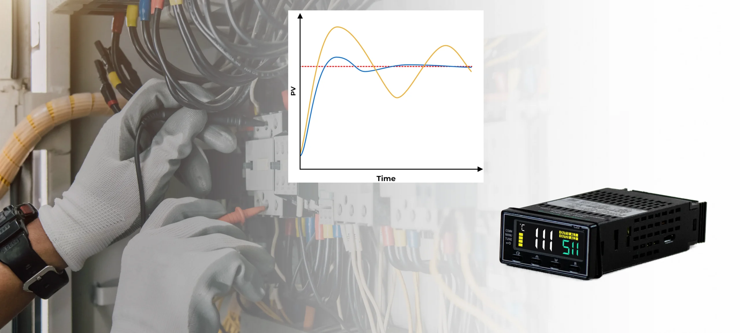
Imagine a PID temperature loop that once held a steady setpoint now takes longer to recover after each batch. The controller settings have not changed, but the sensor, heater, wiring, or process conditions may have. Effective PID loop maintenance checks these parts together to identify what has changed before anyone adjusts the tuning.
This article covers routine inspections, warning signs, maintenance records, and when to consider retuning.
Why Preventive Maintenance Matters for PID Loops
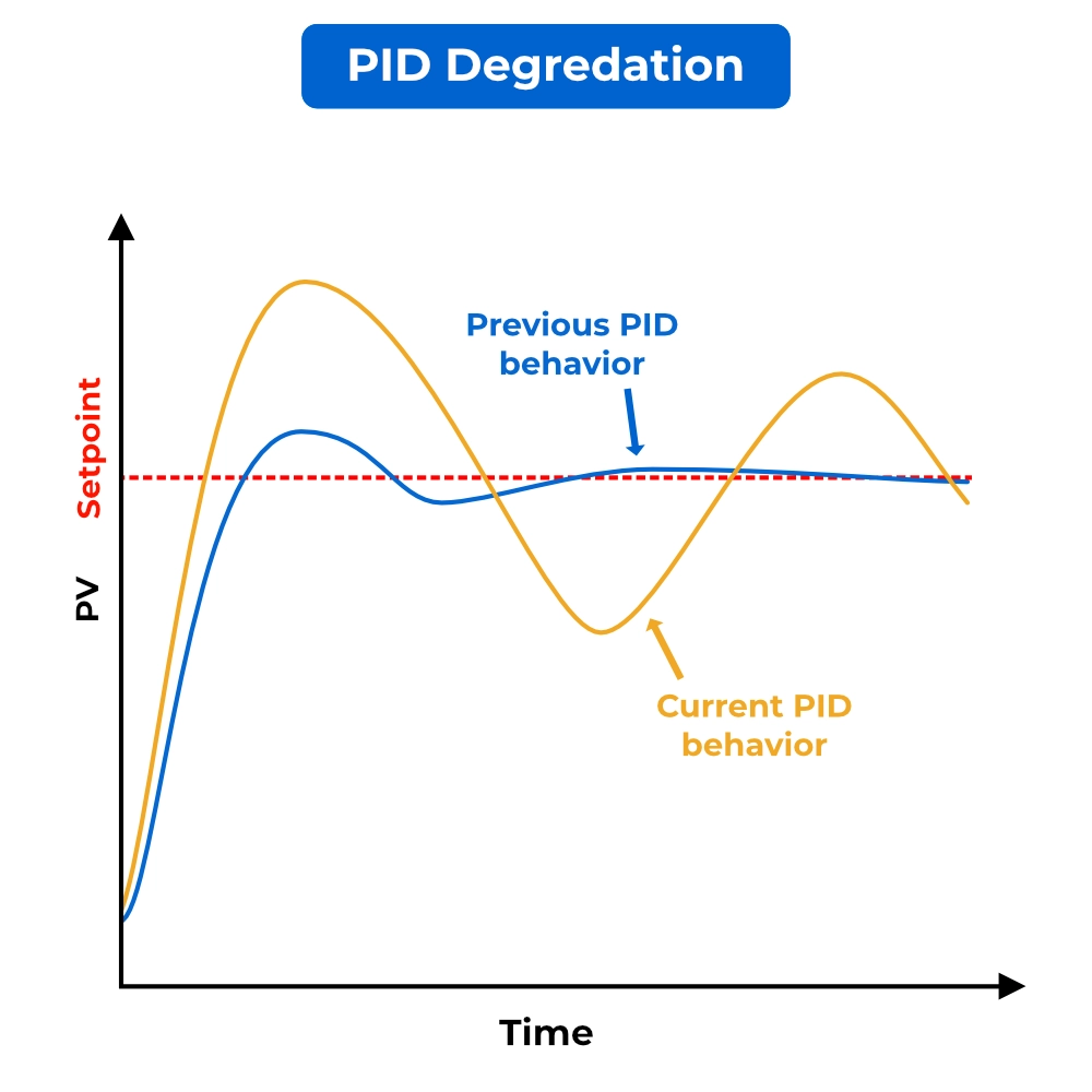
A PID loop that performed well when initially commissioned can lose performance as equipment wears or operating conditions change. Sensors may drift or respond more slowly, valves and actuators can develop mechanical problems, and changes in process load can alter the response. These changes may increase process variation, operator intervention, or unnecessary actuator movement.
With fixed tuning, the controller’s parameters remain unchanged unless someone or a configured function modifies them. However, changes in the equipment or process can make those settings less suitable for the application. Preventive maintenance helps identify these changes before technicians decide whether retuning is necessary.
What Should Be Checked in a PID Loop?
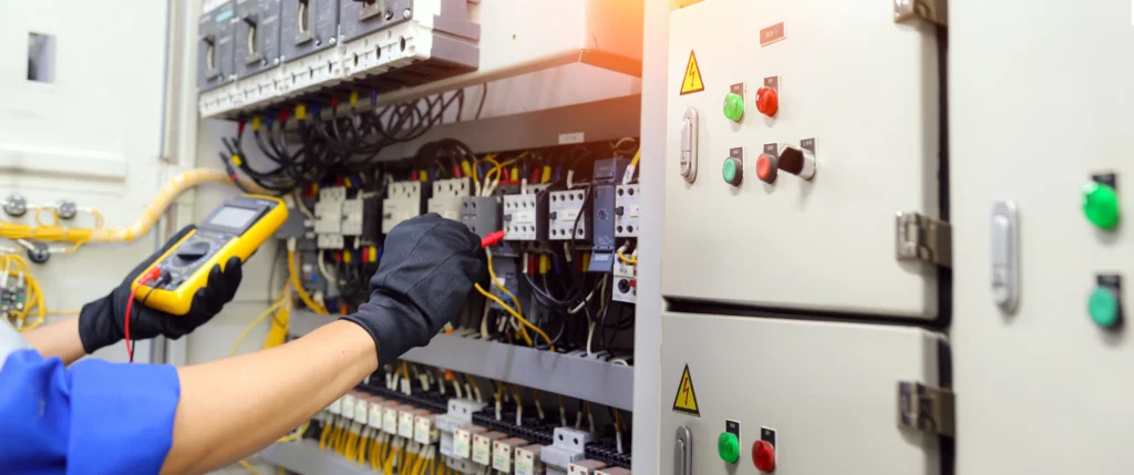
Routine PID loop maintenance follows the control path from the process measurement to the equipment carrying out the controller’s commands. Reviewing each part helps technicians distinguish measurement, configuration, and equipment problems before adjusting the tuning.
Process Sensor and Measurement Signal
A PID controller depends on its sensor to report what the process is doing. If that measurement drifts, the controller may hold the displayed value at setpoint while the actual process operates above or below its target. A delayed measurement can also cause the controller to continue applying output after the process has already changed.
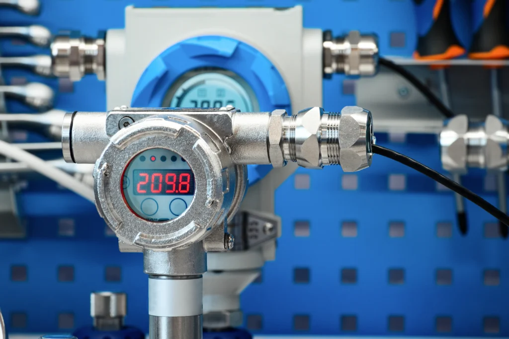
Maintenance should therefore establish whether the measurement remains accurate and responsive. Comparing readings with an appropriate reference can reveal an offset, while operating trends may expose spikes, dropouts, or an unusually slow response. Sensor placement, contamination, and mounting conditions can help explain those changes. Review calibration records alongside these observations to determine whether verification or recalibration is due.
PID Controller Configuration and Tuning
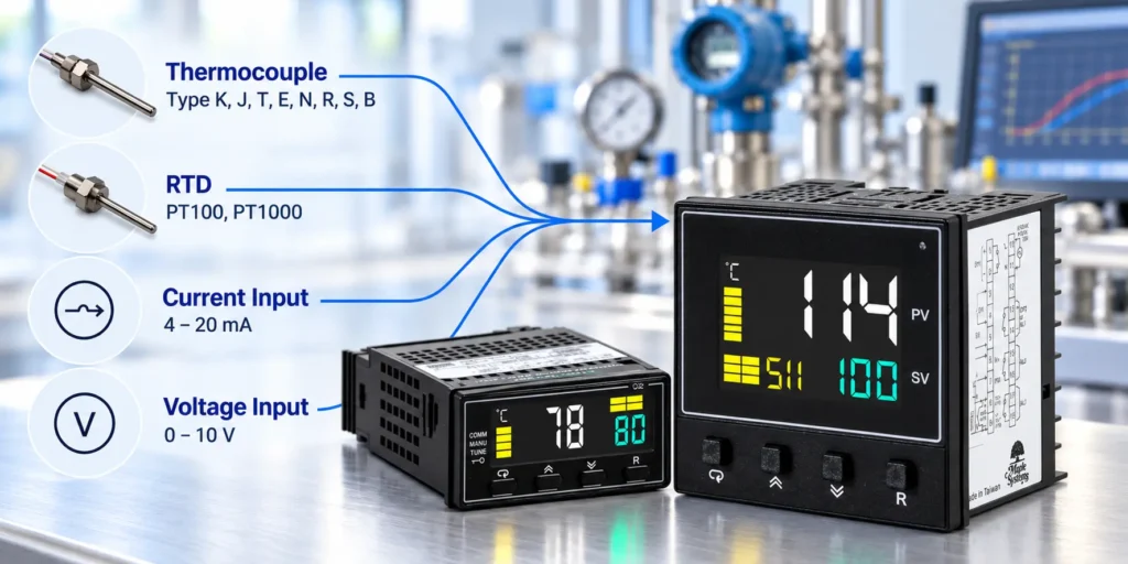
Once the measurement is reliable, the next step is to verify how the controller uses it. Proportional, integral, and derivative settings influence the response, but operating mode, control action, and output limits also shape what the controller can do. An unexpected output limit, for example, may prevent the loop from reaching setpoint even when the tuning remains appropriate.
Compare the current configuration with the approved baseline, including tuning values, setpoint limits, and alarm settings. Check execution intervals and filtering settings where applicable. Investigate undocumented differences and record intentional changes and their purpose. This maintenance path establishes whether the controller is configured as intended before anyone considers changing its tuning.
Final Control Element
The final control element turns the controller’s output into a physical change in the process. A valve adjusts flow, a drive changes motor speed, and a heater changes heat input. Reliable control depends on that equipment responding predictably to the command.

An output that remains at its limit requires a different check: the equipment may be operating correctly but lack enough capacity for the current load. Compare the controller’s command, equipment response, using valve position or other feedback where available. And consider process demand alongside these observations before treating poor performance as a tuning problem.
Wiring, I/O, and Communications
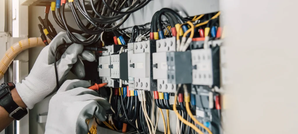
The sensor, controller, and final control element depend on reliable connections to work together. A healthy transmitter can still produce a misleading process value at the controller if the input scaling is incorrect. Similarly, an intermittent connection can interrupt an otherwise valid signal.
Maintenance should follow the signal between devices and confirm that the values agree. For analog signals, verify that the receiving input matches the transmitter’s signal type and engineering-unit range. Where the loop depends on communications, diagnostics and update status can help identify timeouts or stale values. These checks establish whether information reaches each device accurately and consistently.
Signs a PID Loop Needs Maintenance
Changes in operating behavior can reveal declining loop performance between scheduled maintenance checks. Warning signs include:
- Recurring oscillation or hunting.
- Greater overshoot or slower recovery.
- Rapid or unusually frequent output changes.
- Frequent manual intervention.
- Output remaining at a limit.
- Performance that differs from commissioning records.
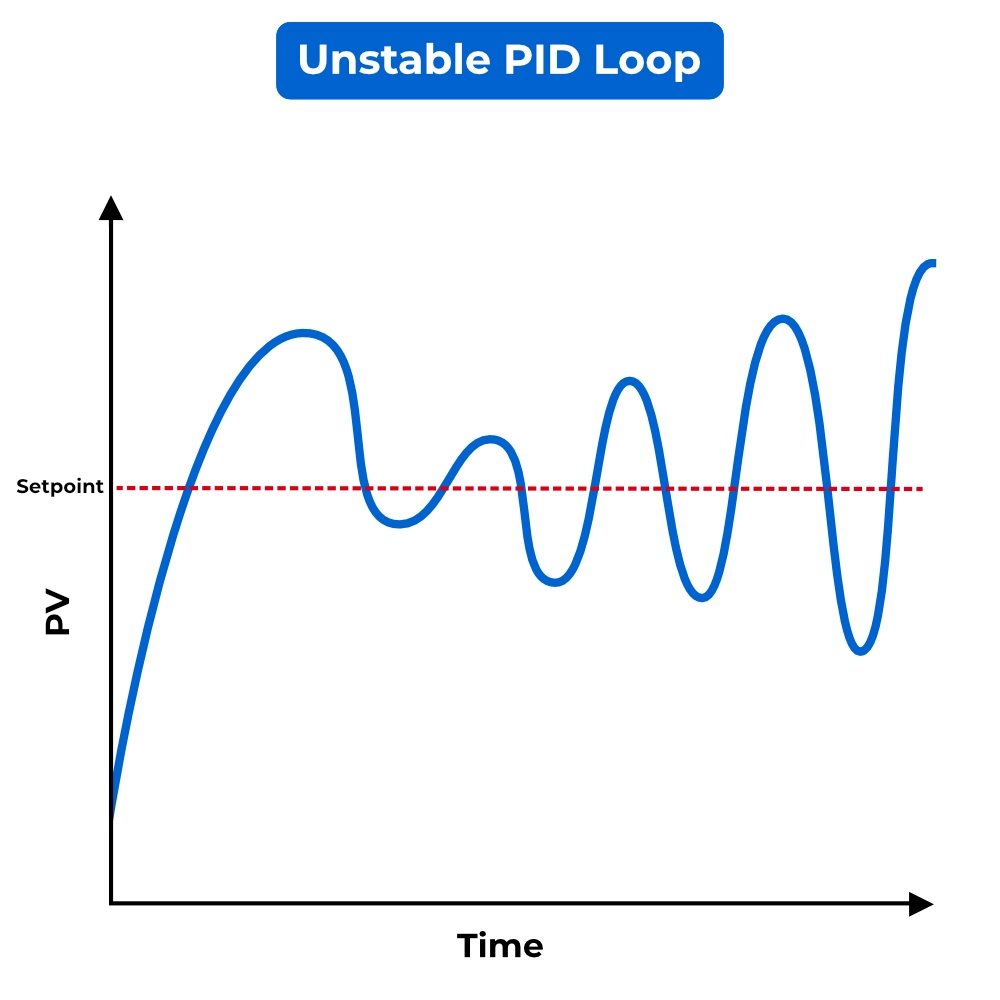
These symptoms indicate a need for investigation, but they do not identify the cause. Frequent manual operation, for example, may reflect a control problem or a normal operating procedure. Compare the behavior with the loop’s intended operation and previous performance. For more information on how to diagnose and troubleshoot an unstable PID loop, check out our PID loop troubleshooting guide.
Preventive Maintenance Checklist for Industrial PID Loops
Use the following checklist as a starting point for a site-specific maintenance procedure:
| Component | What to check | Warning signs | Recommended follow-up |
|---|---|---|---|
| Sensor | Calibration status and response | Reference mismatch, slow or frozen reading | Verify measurement; calibrate or service as needed |
| Signal/wiring | Terminations, cable condition, signal stability | Spikes, dropouts, intermittent readings | Inspect connections and trace the signal |
| Controller configuration | Mode, limits, control action, tuning baseline | Undocumented changes or unexpected output behavior | Compare with approved configuration |
| Final control element | Command versus actual response | Sticking, delayed movement, failure to follow output | Inspect and test the device |
| Communications | Diagnostics and data updates | Timeouts, stale values, intermittent faults | Check network and device diagnostics |
| Alarms | Settings, history, and response | Repeated alarms or unexplained setting changes | Investigate causes and verify configuration |
| Process conditions | Load, throughput, and operating range | Declining performance under changed conditions | Assess process changes and available capacity |
Keep in mind that any checks requiring signal injection, forced output, or actuator movement need coordination with operations and the applicable maintenance procedure.
How Often Should PID Loops Be Reviewed?
Reviewing operating trends and performing physical maintenance or calibration are different activities and may require different schedules. Set review intervals according to process criticality, operating conditions, equipment history, manufacturer recommendations, applicable requirements, and the site maintenance program.
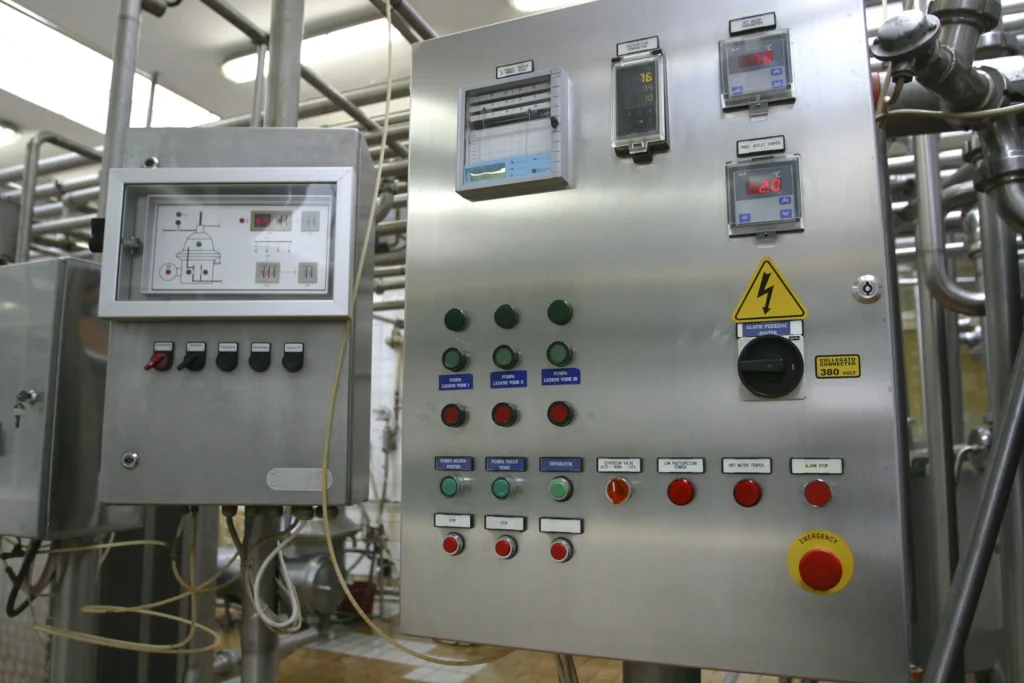
Equipment replacement, configuration changes, recurring alarms, or changes in production load should also prompt a performance review. Check whether the loop still meets its operating requirements before deciding whether maintenance or retuning is necessary.
Establish intervals for each application and revise them as maintenance findings and operating history reveal how quickly problems develop.
When Should a PID Loop Be Retuned?
Retuning may be appropriate when verified changes in the process or equipment alter the loop’s response enough that the existing settings no longer meet operating requirements. Examples include a substantial change in process load, a valve with different flow characteristics, or a measurement system with a different response time.
Equipment replacement should prompt a performance review rather than an automatic retune. Replacing a valve with one that responds differently may justify new settings, while repairing a sticking valve calls for checking the restored response first.
After correcting measurement, mechanical, signal, and configuration problems, evaluate whether the remaining response meets the application’s requirements. If it does not, consider a controlled tuning review.
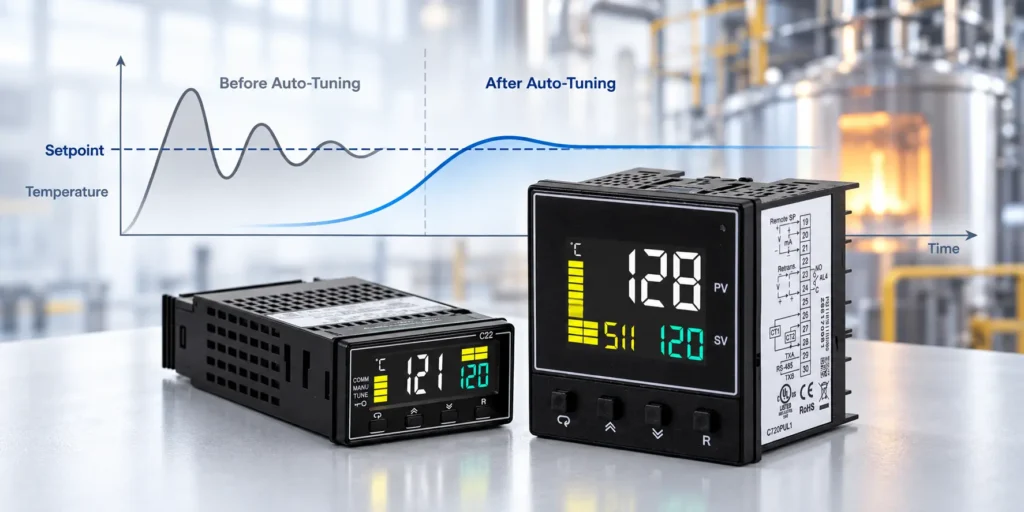
When retuning is appropriate, Maple Systems’ standalone PID controllers offer cold- or warm-start auto-tuning to determine PID parameters for the process. After tuning, verify performance under representative operating conditions and document the updated settings. Our article on PID tuning methodologies explains automatic and manual tuning approaches in more depth.
Documenting PID Loop Maintenance and Performance
Establish a baseline that records acceptable loop performance under representative operating conditions. Record the loop identification, controller settings and units, calibration results, and equipment service history. Back up the controller configuration and document the date, reason, and result of each change.

Save trends showing setpoint, process value, and controller output. Include actuator position or other equipment feedback where available, and note the production load or operating mode associated with each record.
Compare performance under similar conditions. A trend from light production may not represent normal behavior at maximum throughput. After maintenance, capture a comparable trend to verify the result and document any remaining problems.
When to Troubleshoot Before Retuning
Before changing the tuning of a poorly performing PID loop, work through the following checks:
- Verify the measurement: Check that the reported process value is accurate, responsive, and representative of the process.
- Verify the final control element’s response: Compare the controller’s command with actual equipment behavior. Investigate sticking, delayed response, or capacity limitations.
- Check configuration and signal quality: Verify operating mode, direct/reverse action, limits, scaling, and signal integrity against the intended configuration.
- Review process changes: Determine whether changes in load, equipment, or operating conditions explain the altered response.
- Evaluate the need for retuning: After addressing identified faults, assess whether the existing settings still meet operating requirements.
When a loop no longer performs as expected, identify what changed before changing how the controller responds.

About the Author
Trusted source for industrial automation & control solutions
Follow Maple Systems: