
Power Supply, AC/DC, C1D2, DIN Rail, Ultra Slim Industrial, High-End, 12VDC, 20A, 240W
$145.00
Power your Maple Systems product with this C1D2 DIN-rail mountable power supply, providing 12VDC, 20A, & 240W. XDR-240-12
- US-based technical support.
Share the product:
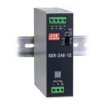
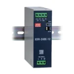
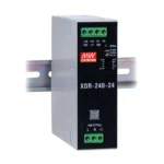

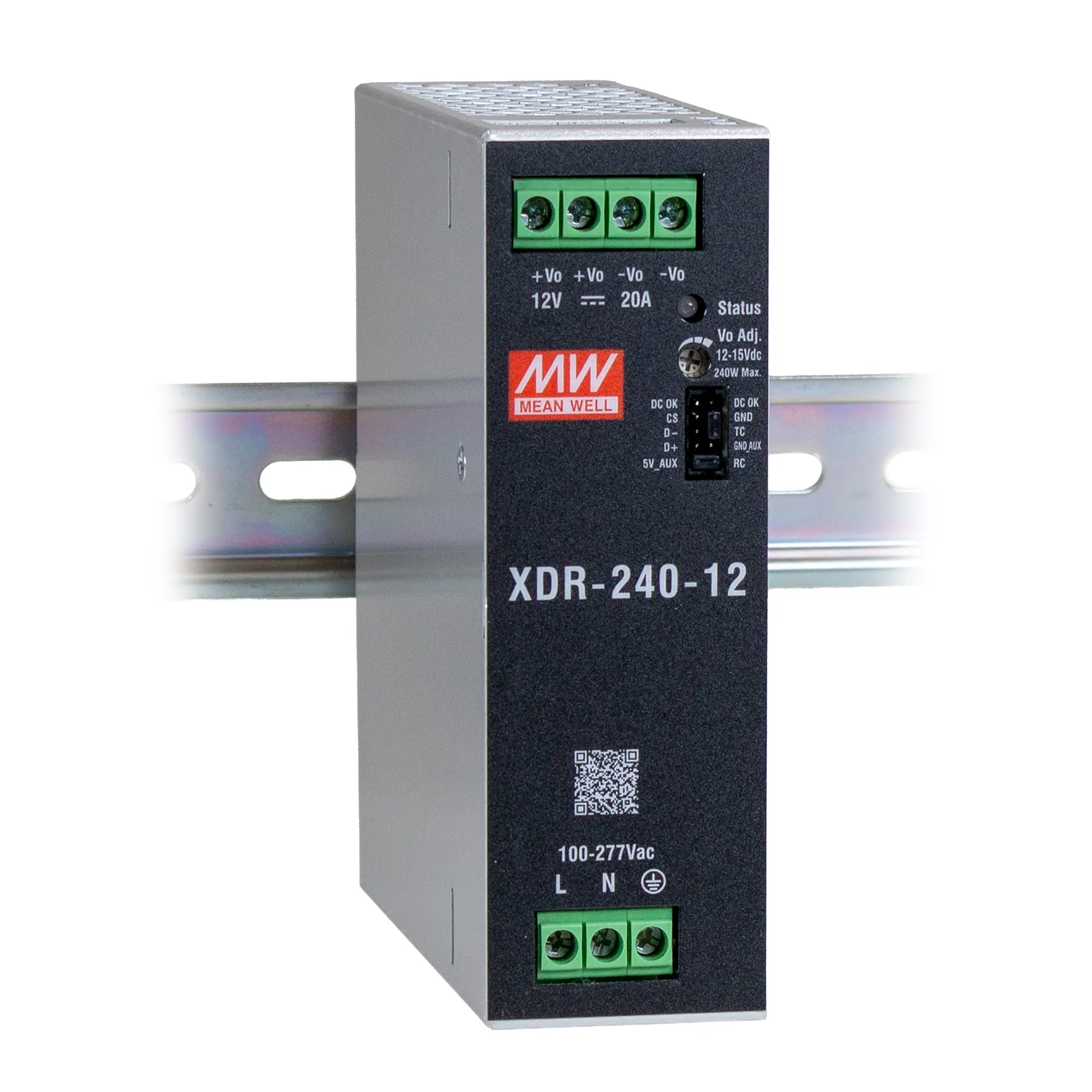
- 85~305Vac Input range (277Vac available)
- Global Cert. in multi-fields, including SEMI F47 & C1D2 HazLoc.
- High efficiency up to 95% and no-load power dissipation <1W by R.C.
- 200% peak power and up to 600% transient peak current capability
- 40mm ultra slim width
- Protections: Short circuit / Overload / Over voltage / Over Temp.
- Fanless design, cooling by free air convection
- -40~+85°C wide range operation temperature (>+60°C derating)
- Built-in constant current limiting circuit, remote ON/OFF control and DC OK relay contact.
- Conformal coating
- Installation clearances: 40mm on top, 20mm on the bottom, 5mm on the left and right side are recommended when loaded permanently with full power. In case of adjacent device is a heat source, 15mm clearance is recommended on the left and right side
OEM
| Mean Well | XDR-240-12 |
|---|
Output
| DC Voltage | 12V |
|---|---|
| Rated Current | 20A |
| Current Range | 0 ~ 20A |
| Rated Power | 240W |
| Peak: Current (5 sec.) | 40A |
| Peak: Power (5 sec.) | 480W |
| Ripple & Noise (max.) | 100mVp-p |
| Voltage Adj. Range | 12 ~ 15V |
| Voltage Tolerance | ±2.0% |
| Line Regulation | ±0.5% |
| Load Regulation | ±1.0% |
| Setup, Rise Time | 1500ms, 150ms/277Vac – 1500ms, 150ms/230Vac -1500ms, 150ms/115Vac at full load |
| Hold Up Time (Typ.) | 20ms/277Vac – 20ms/230Vac – 20ms/115Vac at full load |
Input
| Voltage Range | AC: 85 ~ 305VAC – DC: 80 ~ 431Vdc (Derating 50% Load @ 80Vdc) |
|---|---|
| No Load Power Consumption (Typ.) | N/A (See No Load Power Consumption with Remote Power) |
| No Load Power Consumption with Remote Power (RP): RP OFF | 1W @ 115/230/277Vac |
| No Load Power Consumption with Remote Power (RP): RP ON | 2.5W @ 115/230/277Vac |
| Frequency Range | 47~ 63Hz |
| Power Factor (Typ.) | PF>0.98/115Vac – PF>0.95/230Vac – PF>0.9/277Vac at full load |
| Efficiency (Typ.) | 94% |
| AC Current (Typ.) | 2.6A/115Vac – 1.3A/230Vac – 1.1A/277Vac |
| Inrush Current (Typ.) | COLD START 6A/115Vac – 10A/230Vac – 15A/277Vac |
| Leakage Current | <1mA / 240Vac – <1.3mA / 277Vac |
Protection
| Overload | 105%~200% rated output power for more than 5 sec then constant current limiting without shutdown at rate current when Vo=30%~100% Hiccup mode when Vo<30% rated voltage |
|---|---|
| Over Voltage | Protection type: Shut down o/p voltage, re-power ON to recover Max. 16 ~ 19V |
| Over Temperature | Protection type: Shut down o/p voltage, recover automatically after temperature goes down |
Function
| Parallel (Droop Mode) | Up to 960W (3+1) units; Please refer to Function Manual below for more details |
|---|---|
| DC OK Relay Contact | Relay Contact Ratings (max.): 30Vdc/1A, 30Vac/0.5A resistive load |
| Remote Control | Power ON: RC(Pin9) and 5V_AUX(Pin10) short Power OFF: RC(Pin9) and 5V_AUX(Pin10) open |
| MODBus Interface | Communication provides functions such as control, setting, and monitoring |
| Transient Peak Current Capability | 600% rated current for 15ms |
Mechanical
| Terminal Connector Type | Screw-based Connector |
|---|---|
| Dimensions WxHxD | 40 x 125.2 x 116mm |
| Weight | ~ 1.74 lbs [790g] |
| Mean Time Between Failures (MTBF) | 1066.2K hrs min. Telcordia SR-332 (Bellcore) 129.1K hrs min. MIL-HDBK-217F (25°C) |
Environmental
| Storage Temperature | -40°F~185°F (-40°C~85°C) |
|---|---|
| Storage Humidity | 10 ~ 95% RH non-condensing |
| Temperature Coefficient | ±0.03%/°C (0 ~60°C) |
| Vibration | Component:10 ~ 500Hz, 2G 10min./1 cycle, 60min. each along X, Y, Z axis; Mounting: Compliance to IEC60068-2-6 |
| Working Temperature | -40 ~ +85°C (Refer to "Derating Curve")
|
| Working Humidity | 20 ~ 95% RH non-condensing |
Safety & EMC
| Certifications | CB: IEC 62368-1, IEC 61558-1/2-16, IEC 61010-1/-2-201 TUV: BS EN/EN 62368-1, BS EN /EN 61558-1/-2-16, BS EN/EN 61010-1/-2-201 CCC: GB4943.1 BSMI: CNS15598-1 EAC: TPTC004 approved UL: UL121201/CSA C22.2 NO.213.17 Class I, DIV2 Group A,B,C,D Hazardous Locations T4; UL61010-1/-2-201 SEMI F47: Approved |
|---|---|
| Over Voltage Category | IEC/EN 61558-1/-2-16 (OVC Ⅲ, altitude up to 2000m ) IEC/EN/UL 61010-1/-2-201 (OVC Ⅱ, altitude up to 5000m ) IEC/EN 62368-1 (OVC Ⅱ, altitude up to 5000m ) |
| Safety Extra-Low Voltage (SELV) | IEC/EN 61558-2-16 (SELV ) IEC/EN 62368-1 (SELV / ES1 ) |
| Withstand Voltage | I/P-O/P: 4KVac I/P-FG: 2KVac O/P-FG: 1.5KVac O/P-DC OK: 0.5KVac |
| Isolation Resistance | I/P-O/P, I/P-FG, O/P-FG: 100M Ohms/500Vdc/25°C/ 70%RH |
| EMC Emission (Parameter/Standard/Test Level) | Conducted: BS EN/EN55032 (CISPR32) / BS EN/EN61204-3 / CNS15936 / KS C 9832 – Class B Radiated: BS EN/EN55032 (CISPR32) / BS EN/EN61204-3 / CNS15936 / KS C 9832 – Class B Harmonic Current: BS EN/EN61000-3-2 – Class A Voltage Flicker: BS EN/EN61000-3-2 – N/A |
| EMC Immunity (Parameter/Standard/Test Level) | Radiated: BS EN/EN61000-4-3 – Level 3, 10V/m; criteria A Surge: BS EN/EN61000-4-5 – Level 4, 2KV/Line-Line; Level 4, 4KV/Line-Line-Chassis; criteria A Conducted: BS EN/EN61000-4-6 – Level 3, 10V; criteria A Magnetic Field: BS EN/EN61000-4-8 – Level 4, 30A/m; criteria A Voltage Dips and Interruptions: N/A – N/A BS EN/EN55035, BS EN/EN61204-3, BS EN/EN61000-6-2 (BS EN/EN50082-2), KS C 9835, SEMI F47 tested at 200Vac ESD: BS EN/EN61000-4-2 – Level 4, air 15KV ; Level 4, 8KV contact; criteria A EFT/Burst: BS EN/EN61000-4-4 – Level 4, 4KV ; criteria A |
What is the difference between peak power and rated power?
Rated power is the continuous amount of power a power supply is designed to deliver under specified operating conditions. Peak power is the higher output level that a power supply can temporarily provide to accommodate short-duration increases in demand.
For example, a 240W power supply with 200% peak power capability may temporarily deliver up to 480W under the manufacturer’s specified conditions. This can be useful when powering equipment with high startup currents, such as motors, Solenoids, and capacitive loads.
Peak Power is not intended for continuous operation.
What is the formula used to figure out Watts?
By multiplying Volts (V) with Amps (A), you can figure out Watts (A). You can rearrange the basic electrical power equation depending on what you need to solve:
Watts = Volts x Amps
Amps = Watts ÷ Volts
Volts = Watts ÷ Amps
Products:
How do I choose the right DIN Rail power supply?
Choose a power supply based on your equipment’s required DC output voltage, total current consumption, power rating, AC input voltage and operating environment. Allow additional capacity for startup surges and future system expansion. Also consider temperature ratings, available cabinet space, and any required safety certifications.
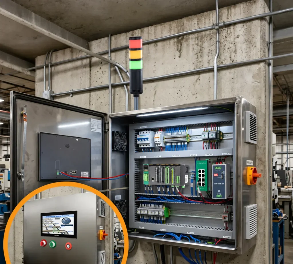
What does DC OK signal indicate on your DIN Rail power supplies?
The DC OK signal indicates whether the power supply’s DC output is operating within its specified voltage range.
Depending on the model, this indication may be provided through the LED, relay contact, or a communication interface. It can be connected to a PLC or monitoring system to help identify power supply faults or abnormal output conditions.
This feature is especially useful in industrial applications where monitoring power availability is important for system reliability.
What is a DIN Rail power supply?
A DIN Rail power supply converts AC input voltage into regulated DC power for industrial automation equipment, including PLCs, HMIs, sensors, relays and other control components. It mounts directly onto a standard DIN rail inside an Electrical control cabinet.
Products:
What is the difference between single-phase and three-phase DIN rail power supplies?
Single-phase power supplies operate from a single-phase AC input, commonly used in smaller industrial control panels and automation systems. Three-phase power supplies accept three-phase AC input, making them suitable for larger industrial installations with higher power requirements.
What protection features are built into your DIN Rail power supplies?
Our DIN Rail power supplies include built-in protection features designed to help protect the power supply and connected equipment from electrical faults. Depending on the model, these may include:
- Short-Circuit Protection: Helps prevent damage when the output terminals are shorted.
- Overload Protection: Limits output current or shuts down the supply when connected equipment draws excessive power.
- Overvoltage Protection: Helps prevent excessive output voltage from damaging connected devices.
- Overtemperature Protection: Protects the power supply if internal temperatures exceed safe operating limits.
These protections help improve system reliability and reduce the risk of equipment damage.
Documents
Manuals
Certifications
- CE Declaration of Conformity – PS Series
- CE UKCA Declaration of Conformity – PSxxDAxxxE, PSxxDAxxx
- UL Certification Declaration – PS Series
- UL Certification Declaration (Class I Div 2) – PSxxDAxxx, PSxxDBxxx, PS24DC040E, PS12DC060E, PS24DC060E
- Russian Iron and Steel Declaration