
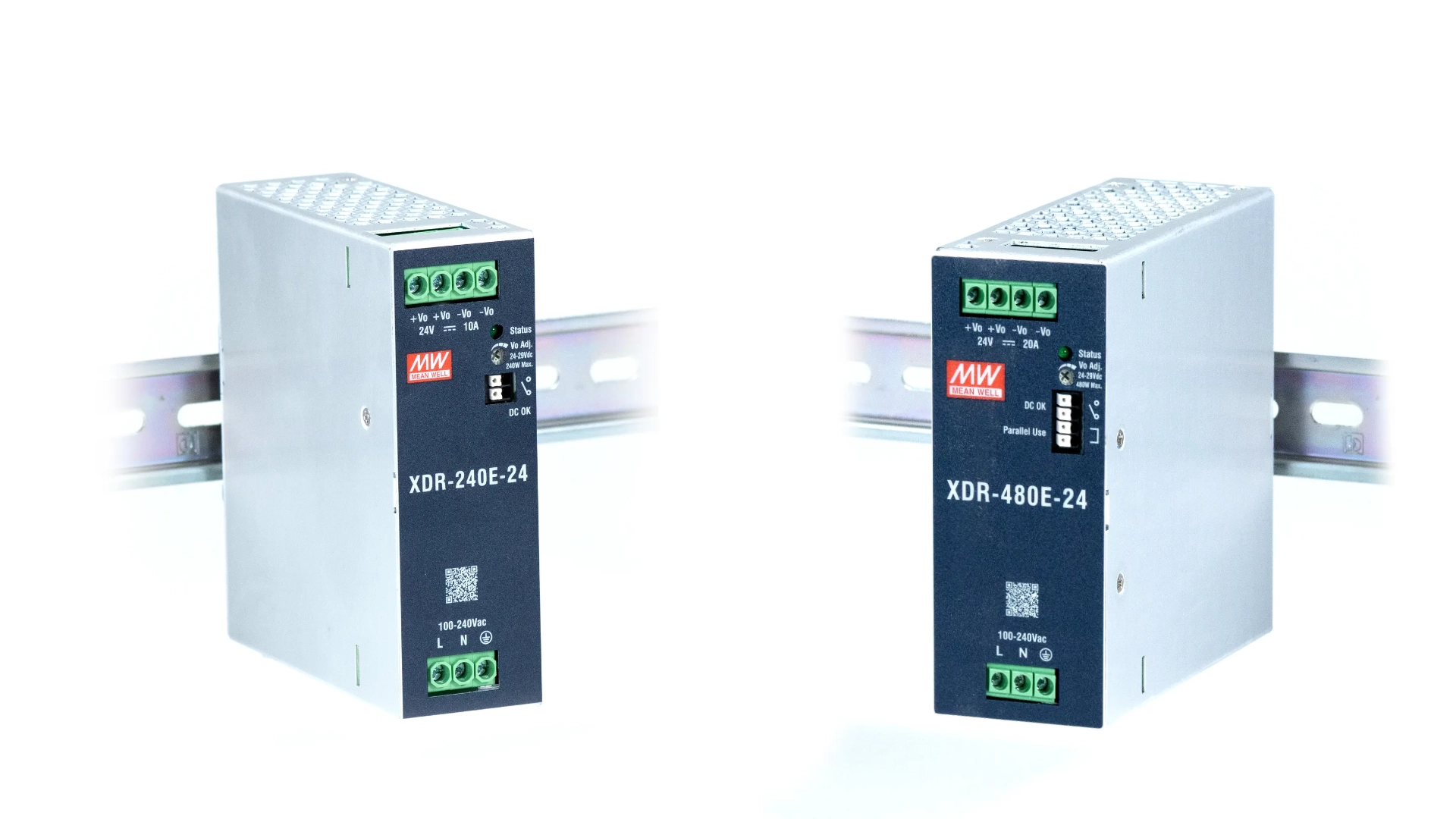
Imagine a control cabinet in which a single power supply runs a PLC, HMI, and industrial PC without difficulty during normal operation. During testing, however, the output voltage begins to drop when the IPC processes multiple images from a machine vision system. Although the connected equipment appeared to fit within the supply’s rated capacity, the calculation failed to account for how the load changes during operation. Effective DIN-rail power supply selection must consider both the electrical demand and the conditions inside the completed enclosure.
Selection begins with matching the output voltage to the connected equipment and calculating the highest credible continuous and peak loads. Designers must then account for input power, environmental derating, protection and diagnostic features, regulatory requirements, and the space available inside the panel.
What a DIN-Rail Power Supply Does in a Control Panel
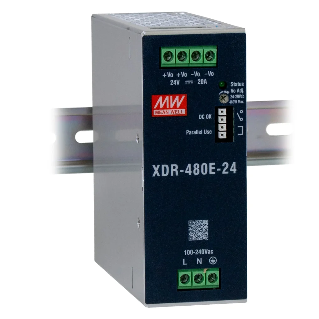
A DIN-rail power supply converts a facility’s AC or DC power into regulated low-voltage DC power. This DC power is used for PLCs, HMIs, sensors, relays, communication equipment, and other control-panel devices. Its rail-mounted design allows it to install alongside these components within the enclosure. Because the input and output ranges vary by product, designers must match both sides of the supply to the electrical system.
Determine the Required DC Output
After identifying the equipment the power supply will serve, designers must determine both the voltage it requires and the amount of current it may draw. The output voltage must match the connected devices, while the supply’s current and power ratings must support the largest credible combination of continuous and peak loads. These requirements should be evaluated together: selecting the correct voltage does little good if the supply cannot deliver enough current when the system reaches its highest demand.
Match the Supply to the Load Voltage
The DIN-rail power supply’s nominal output voltage needs to match the input requirements of the equipment it will power. Although 24VDC is common in industrial control panels, some devices require 12VDC or 48VDC. Review the specified input range for every PLC, HMI, sensor, relay, communication device, and other load connected to the supply. A device’s current rating only applies at its specified operating voltage, so voltage selection must come before calculating the panel’s total current and wattage.
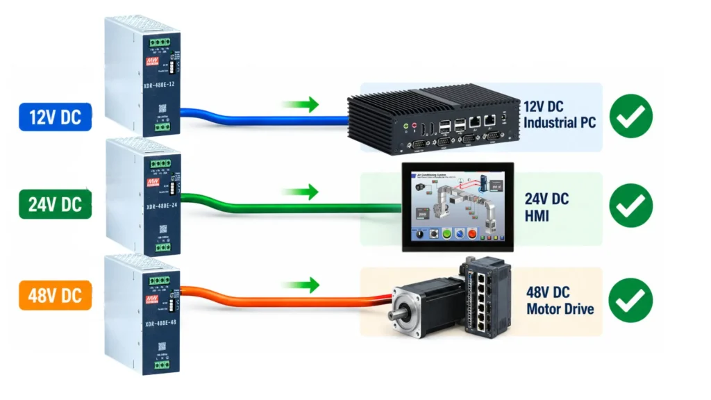
Equipment with different voltage requirements should not share the same power circuit unless every device accepts the voltage. A panel containing both 24VDC and 12VDC loads may instead require separate power supplies or a properly sized DC-to-DC converter.
Designers should also verify the required voltage at the load rather than only at the supply terminals. Long conductors, small wire sizes, and high current can create voltage drop between the power supply and connected equipment. The supply must keep each device within its permitted input range under the panel’s full range of operating conditions.
Calculate Continuous Current and Power
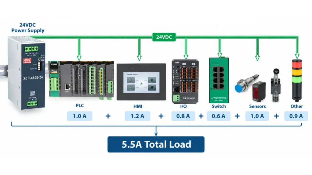
After establishing the output voltage, build a load schedule that records the maximum current drawn by every connected device. Add the loads that can operate simultaneously to calculate the required continuous output current. Multiplying that current by the nominal output voltage provides the corresponding power requirement:
Power (W) = Voltage (V) × Current (A)
For example, a group of 24VDC loads drawing 5.5A requires 132W under that operating condition. Both current and power must remain within the selected supply’s ratings.
Account for Peak Loads and Future Expansion
Some loads draw more current during startup or activation than their normal operating demand suggests. Motors, solenoids, contactor coils, capacitive electronic loads, and industrial computers can create short-duration peaks capable of pulling down the output voltage or activating overload protection. The selected supply must accommodate peak loads, environmental derating, and reasonably anticipated panel additions. There is no universal headroom percentage: the appropriate margin depends on load behavior, the manufacturer’s derating curves, and future expansion plans.
Check the Output Adjustment Range
Some power supplies allow limited adjustment around their nominal output voltage. For example, Maple Systems’ 24VDC models reviewed here provide an adjustment range of 24V to 29V. This adjustment may help account for expected voltage drop while maintaining the required voltage at the load.
However, the adjusted output must remain within the permitted input range of every connected device. Voltage adjustment cannot correct undersized conductors, excessive cable length, poor connections, or an improperly designed distribution circuit.
Check Input Power, Inrush Current, and Hold-Up Time

After determining the required DC output, designers must confirm that the power supply is compatible with the panel’s incoming power and upstream protective devices. Input-voltage range, normal input current, startup inrush, and hold-up time can all affect how the supply performs as part of the complete electrical system.
Confirm the Available Input Range
Start by comparing the power supply’s input-voltage and frequency ratings with the power available at the installation. Maple Systems offers several DIN-rail power-supply input ranges. The E-series single-phase models accept 85-264VAC or 120-370VDC, while the wider-input single-phase models accept 85-305VAC or 80-431VDC, with output derating specified at the lowest DC input. Three-phase models accept 320-600VAC or 450-800VDC and can also support dual-phase operation under specified derating conditions. These high-voltage DC input ranges should not be confused with the low-voltage DC supplied to connected equipment.
Input current changes with both the source voltage and the power delivered to the load. Designers should therefore use the datasheet values for their selected model and input voltage when sizing conductors, disconnects, fuses, breakers, and other upstream components.
Understand Hold-Up Time
Hold-up time describes how long a power supply can maintain its regulated output after the input voltage disappears. Hold-up time varies across Maple Systems power-supply families based on the model, input voltage, load, and phase configuration. For example, the single-phase 240W families specify 20ms, while the single-phase 480W families specify 15ms under their stated test conditions. Other models differ, so designers should consult the selected supply’s datasheet rather than estimating hold-up time from wattage alone.
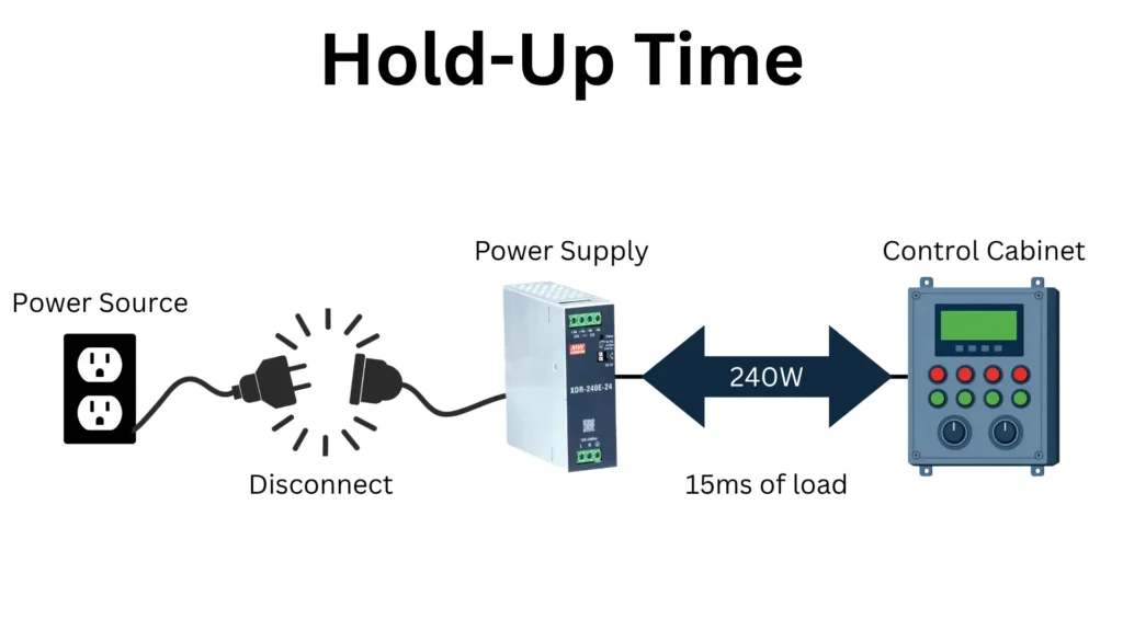
This stored energy may carry control equipment through a very brief input interruption, reducing the chance of an immediate PLC reset or communication dropout. However, actual performance depends on the operating load and input conditions. Hold-up time should not be treated as backup power or used in place of a UPS when the system must continue operating through longer outages.
Account for Temperature, Derating, and Panel Layout
A power supply’s rated wattage does not necessarily represent the power it can deliver under every operating condition. Ambient temperature, installation altitude, nearby heat sources, and component spacing all affect the supply’s ability to release heat. Designers must evaluate these factors together to determine how much output capacity will actually remain available inside the completed control panel.
Temperature and Derating
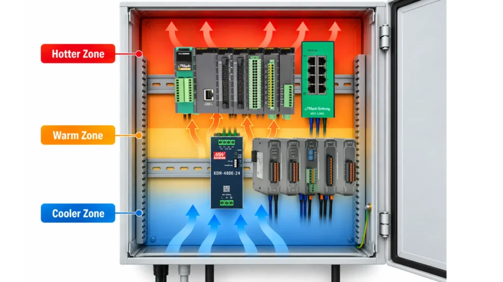
Enclosed control panels can become substantially warmer than the surrounding room as power supplies, drives, controllers, and other components release heat. Designers should therefore base their calculations on the expected temperature around the power supply rather than the room’s ambient temperature. Derating reduces the amount of current or power that a supply can safely deliver as operating conditions become more demanding. A supply that meets the load requirement at room temperature may become undersized at the enclosure’s actual operating temperature.
Consider Other Environmental Factors
Altitude also limits cooling because thinner air transfers heat less effectively. For installations above 2,000 meters, Maple Systems’ datasheets specify reducing the maximum permitted ambient temperature by 3.5°C for every additional 1,000 meters with fanless models. Designers may need to reduce the load, improve enclosure cooling, or select a higher-capacity supply.
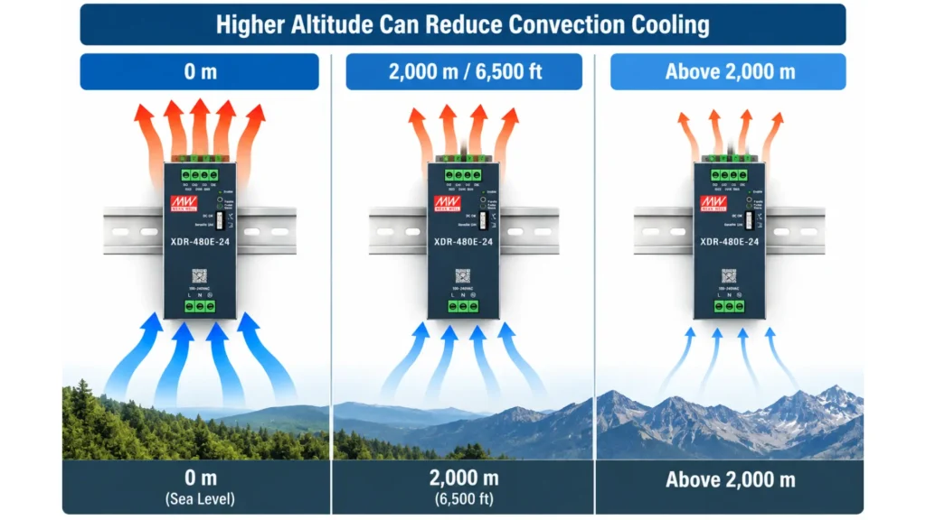
Humidity, condensation, and vibration may not directly reduce the rated output, but they still determine whether a supply is suitable for the installation. Designers should compare these conditions with the manufacturer’s operating and storage specifications.
Plan the Layout and Thermal Solution
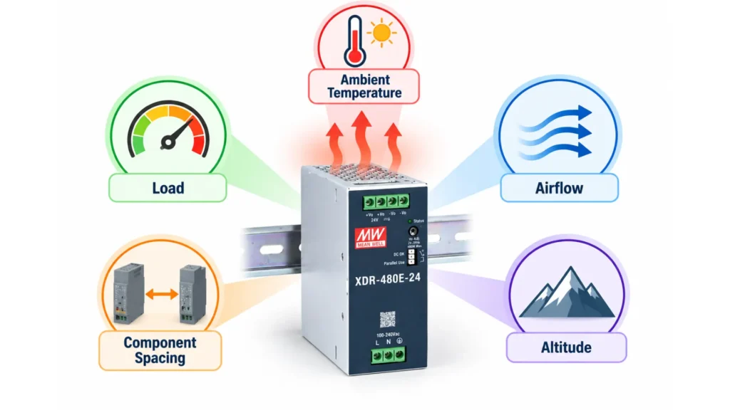
Power supply manufacturers specify installation clearances that allow heat to escape through natural airflow. Panel layouts must preserve these clearances and avoid crowding the supply with wiring ducts or other heat-producing components. If passive airflow cannot maintain acceptable operating conditions, the enclosure may require ventilation, active cooling, or a higher-capacity supply operated below its maximum rating. For a closer look at these considerations, read our article on DIN-rail power supply derating and thermal management.
Compare Protection, Monitoring, and Redundancy Features
Two power supplies with the same voltage and wattage may respond very differently to an overload, high temperature, or internal fault. Designers should therefore look beyond rated output and compare how each supply protects the connected equipment, communicates its operating status, and supports applications that require additional capacity or availability.
Understand How the Supply Responds to Faults
Overload protection limits the current or power delivered when the connected load demands more than the supply can safely provide. Overload behavior varies by Maple Systems power supply family. Depending on the model, overload protection may use constant-current limiting, hiccup-mode recovery, output shutdown, or a combination of these responses. Some models enter hiccup mode when the output voltage falls below a specified percentage of its rated value, while others continue limiting current or require input power to be cycled after certain faults. Designers should consult the selected model’s datasheet to determine its overload threshold, peak-power capability, and recovery behavior.
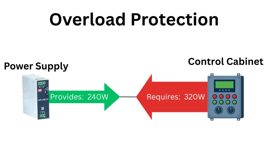
Maple Systems’ units also provide overvoltage protection and overtemperature protection. Overvoltage protection enters hiccup mode and recovers after the fault condition is removed. Overtemperature protection shuts down the output and restores it after the supply cools. Designers should confirm that these recovery behaviors are appropriate for the machine, since automatically restoring power may require additional consideration in safety-related applications.
Use the DC OK Contact for Power Monitoring

Protection circuitry helps the supply respond to a fault, but operators and controllers also need a way to detect that the power system has changed. Maple Systems power supplies include a normally closed DC OK relay contact that can connect to a PLC input, alarm circuit, or other monitoring device. The contact opens when the supply no longer reports its defined DC OK condition.
By monitoring this contact, the control system can generate an alarm, record a power event, or initiate an orderly response when the supply no longer reports normal output. The contact does not identify the underlying cause by itself, so troubleshooting may still require checking the input source, connected load, wiring, temperature, and power supply. If you would like to learn more, we have an article about the DC OK contact on Maple Systems power supplies.
Evaluate Parallel Operation and Redundancy
Some systems need more current than one supply can deliver or must continue operating if a single supply fails. Select Maple Systems power supply families support droop-mode parallel operation, with as many as four units in a 3+1 arrangement. The 240W non-E family supports up to 960W, the 480W families support up to 1,920W, and the 960W families support up to 3,840W. The 240E and three-phase 240W families don’t support parallel operation, so designers must verify this feature at the family level rather than relying on wattage alone.
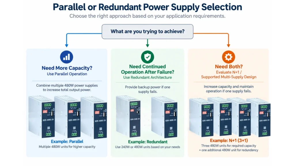
However, parallel operation does not automatically create a redundant system. A capacity-focused arrangement may require every connected unit to meet the load, leaving no reserve after a failure. A redundant configuration instead provides enough remaining capacity to support the load when one supply becomes unavailable. Designers must follow the manufacturer’s approved function manual and consider load sharing, output isolation, fault detection, and upstream circuit protection when designing either arrangement. If you would like to learn more, you can read our article on Parallel vs. Redundant Power Supply systems.
Verify Safety and EMC Requirements
A DIN-rail power supply must meet the standards and approvals required for the machine, installation environment, and destination market. Depending on the model, Maple Systems power supplies are evaluated to applicable standards that include IEC, EN, and UL 61010-1 and 61010-2-201, along with relevant EMC emission and immunity standards. Designers should verify the exact approvals and certifications listed for the selected model and destination market.
However, a component-level certification does not automatically certify the completed control panel or machine. The final equipment must still be evaluated for applicable electrical safety and electromagnetic compatibility requirements. Designers should verify the exact approvals for the selected model and confirm that its overvoltage category, insulation ratings, operating altitude, and EMC performance align with the completed system.
Select the Power Supply as Part of the Complete Panel
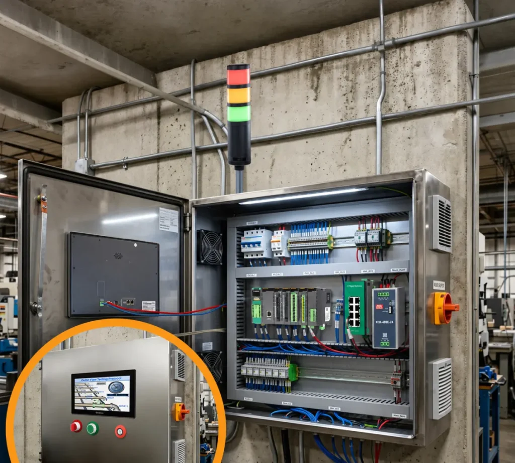
DIN-rail power supply selection requires more than matching voltage and nameplate wattage. The selected supply must support the highest credible continuous and peak demand after accounting for input conditions, environmental derating, panel layout, fault response, monitoring, expansion, and regulatory requirements
Evaluating these factors as part of the complete control panel helps prevent nuisance shutdowns, unexpected voltage drops, and premature component failure. It also ensures that the supply has enough usable capacity under real operating conditions, not only the nameplate rating.
Maple Systems offers compact DIN-rail power supplies spanning approximately 75W to 960W, with 12VDC, 24VDC, and 48VDC output options. The lineup includes single-phase and three-phase input families, wide AC and DC input ranges, DC OK relay monitoring, and built-in overload, overvoltage, and overtemperature protection. Select models also support droop-mode parallel operation, extended operating-temperature ranges, and higher-power 3+1 configurations. Compare the available output capacities and operating specifications to find a power supply suited to your next industrial control panel.

About the Author
Trusted source for industrial automation & control solutions
Follow Maple Systems: