


Imagine you’ve just deployed a full control panel. It’s a prototype for a new machine your company will be manufacturing. You plug in the power supply, and the cabinet jumps to life. Indicator lights flash as the PLC runs through your test program, while the HMI on the front operates perfectly. When you return an hour later, however, the cabinet is dark, despite still being plugged in. Inside, the power supply still appears energized, but the connected equipment no longer appears to be receiving proper DC power. A DC OK relay contact can make this type of problem visible to an external PLC or monitoring system.
This article explains what a DC OK relay contact reports, how it connects to a control system, and how engineers can use its signal for alarms, troubleshooting, and redundant power monitoring.
What a DC OK Relay Contact Does
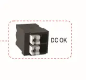
A DC OK relay contact is a status output that changes state according to the condition of the power supply’s DC output. The power supply monitors its own output voltage, and an internal relay changes state when that DC output enters or leaves the manufacturer’s defined acceptable range. An externally powered monitoring circuit will detect this state, which can then be interpreted by a PLC, HMI, or other monitoring system.
A DC OK relay contact differs from an active DC OK output. A relay contact acts as an isolated switch within an externally powered monitoring circuit. An active output uses an electronic switching device, such as a transistor, and must be connected according to its specified voltage, polarity, and reference requirements. Maple Systems’ new DIN-rail power supplies use relay contacts. This allows the monitoring circuit to supply a voltage compatible with the connected PLC input, provided it remains within the contact’s published ratings.
What the DC OK Signal Reveals About the Power Supply
A power supply’s DC OK contact indicates whether the DC output meets the manufacturer’s defined conditions. But it does not identify why the output became abnormal. A status change could result from:
- A loss of AC input
- Excessive connected load
- A downstream short circuit
- Overtemperature shutdown
- Another protective response
- A wiring fault that pulls the supply output outside its acceptable range
- An internal power-supply failure
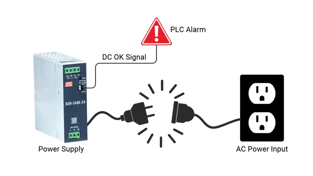
To summarize, DC OK provides an early indication and a starting point for troubleshooting, not a complete diagnosis.
What DC OK Monitoring Does Not Measure
First, DC OK is not the same as AC-input monitoring. The output may remain available briefly after incoming power disappears (based on the power supply’s hold-up time). The input may also remain present while an overload or thermal condition disrupts the output of the power supply.
Second, DC OK does not provide a continuous voltage measurement. Instead, it provides a discrete normal-or-abnormal status. An application that needs exact voltage, output-current data, adjustable limits, or historical trends will require additional monitoring.
Overload, overvoltage, and overtemperature protection can each affect the power supply’s output differently. Our guide to industrial power supply protection modes explains how these responses work.
Connecting a DC OK Relay to a PLC or Monitoring System
In a typical control panel, the DC OK relay forms part of a low-current circuit connected to a PLC digital input. When the relay changes state, the PLC detects the input transition and applies the programmed alarm or response. Because the relay contact does not generate a PLC input signal, the monitoring circuit must provide a compatible sensing voltage. This voltage may come from the monitored supply, although independently powered monitoring is necessary if the system must record or communicate a complete loss of that supply.
For example, a 24 V PLC input circuit could route its monitoring voltage through the DC OK contact and then into a digital input. While the power supply reports that its output is operating normally, the contact holds the input in one state. If the output leaves the power supply’s acceptable range, the relay changes state and the PLC detects the transition. Contact behavior varies between power supplies, so designers must verify it in the model-specific documentation. The DC OK contacts on Maple Systems’ power supplies remain closed while the output is normal and open when the supply reports a DC failure.
The monitoring circuit must also remain powered when the monitored supply loses its output. If the same power supply operates both the PLC and its input circuit, a complete loss of DC output may shut down the PLC before it can record or communicate the alarm. Critical applications may therefore use an independently powered controller, a redundant supply, or another monitoring device that remains operational when the monitored supply becomes unavailable.
| Observed state | DC OK contact | PLC input | Interpretation |
|---|---|---|---|
| Normal DC output | Closed | On | Supply reports DC OK |
| Abnormal DC output | Open | Off | Supply reports DC failure |
| Broken monitoring wire | Circuit open | Off | Monitoring fault or DC failure |
| Monitoring circuit unpowered | State may be unknown | N/A | Monitoring power must be checked |
Electrical Compatibility Checks
Before making the connection, designers must compare the relay’s contact rating with the voltage and current used by the monitoring circuit. Maple Systems’ power supplies rate their DC OK relay contacts for up to 30 VDC at 1 A or 30 VAC at 0.5 A with a resistive load. The PLC input voltage, input current, common connection, and sinking or sourcing configuration must also be compatible with the monitoring circuit. These ratings describe what the contact can safely switch. They do not mean that the DC OK terminals provide that voltage or current. Designers should also confirm the relay’s switching threshold, delay, and behavior during startup, shutdown, and protective operation in the model-specific documentation.
Healthy-State and Fault-State Logic in Alarm Programming

Once connected, the PLC program can convert the input state into a useful alarm. Depending on the contact arrangement, the system may keep the input active while the power supply is healthy and allow it to turn off during a fault. This approach can also help reveal a broken monitoring wire, since both a lost DC OK condition and an open wire may cause the input to drop out. However, this arrangement should not be described as fail-safe or safety-rated unless the entire monitoring system has been designed and certified for that purpose.
The PLC or HMI should describe only the condition confirmed by the signal. An alarm such as “24 V Power Supply Output Not OK” is more accurate than “Power Supply Failed.” Because the relay cannot identify the cause of the problem. Loss of input power, an overload, a short circuit, excessive temperature, wiring problems, or an internal power supply fault could all result in an abnormal output condition. The control system can record the event, display an alarm, notify a remote operator, and direct maintenance personnel toward additional electrical checks.
Industrial Applications for DC OK Monitoring
Once a DC OK relay contact connects to a PLC or other monitoring device, its status can support more than a single power-supply alarm. The same signal can help technicians isolate shared control-panel faults, monitor equipment in unattended locations, and detect when a parallel or redundant power system has lost one of its supplies.
Control-Panel Fault Detection
Using a DC OK relay contact, a PLC can monitor the supply powering sensors, I/O modules, relays, HMIs, and other control equipment. If multiple devices stop responding simultaneously, DC OK status helps technicians determine whether to inspect each device individually or to check the shared power supply first.

Remote and Unattended Equipment
DC OK monitoring can also provide information that would otherwise remain limited to a local indicator light. Added visibility is especially useful in environments like:

- Remote pumping systems
- Water and wastewater equipment
- Building-automation panels
- Unattended production cells
- Distributed equipment cabinets
The contact itself doesn’t send a notification. The connected PLC, HMI, gateway, or supervisory platform must communicate the DC OK state change. Retaining event history, a feature available in EBPro for Maple Systems’ HMIs, can also help technicians investigate intermittent resets, voltage interruptions, thermal shutdowns, and overloads that clear before anyone reaches the cabinet.
Parallel and Redundant Power Systems
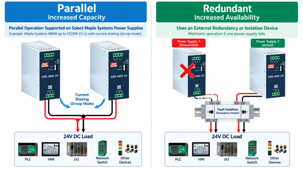
In a parallel or redundant power system, individually monitoring each power supply can reveal the loss of one unit while the remaining supplies continue carrying the load. This visibility is especially useful because everything may continue to operate normally, even after redundancy has been lost. Without individual status monitoring, the degraded condition might remain hidden until a full fault occurs.
Parallel operation alone does not create redundancy. Designers must also account for capacity after one unit is lost, current sharing, fault isolation, and the manufacturer’s connection requirements. For more information, read our article on parallel vs redundant power supplies.
Conclusion
A power supply problem can affect multiple components at once. But without a status signal, the control system may only see the resulting device faults and communication losses. A DC OK relay contact brings the condition of the power supply itself into that monitoring environment. Instead of relying entirely on someone opening the cabinet and checking an indicator light, the PLC can record the status change, present a more useful alarm, and direct technicians toward the shared power source.
A DC OK relay contact cannot diagnose every electrical problem. It can tell the control system when the supply’s output no longer meets its defined operating condition. With appropriate PLC logic, alarm history, and supporting electrical measurements, that signal can improve fault visibility, shorten troubleshooting, and reveal the loss of redundancy before it leads to a shutdown.
When selecting a DIN-rail power supply, designers should therefore consider not only how much power it can deliver, but also how the system will detect and respond when that output becomes unavailable. Maple Systems’ DIN-rail power supplies include DC OK relay contacts. These contacts remain closed while the DC output is normal and open when the supply reports a DC failure.
FAQ
What does DC OK mean on a power supply?
The DC OK signal indicates whether the power supply’s output meets the manufacturer’s defined operating conditions, with exact thresholds and timing determined by the product documentation.
Is a DC OK relay contact a dry contact?
Many DC OK relay outputs are potential-free or dry contacts, but users must confirm this in the specific product’s documentation rather than relying only on the terminal label.
Can a DC OK contact connect to a PLC input?
It can often form part of a PLC input circuit, provided the contact rating, PLC input voltage, sinking or sourcing arrangement, and wiring reference are compatible.
Does DC OK detect an AC power failure?
DC OK contacts monitor the DC output condition. Loss of AC input may eventually cause the status to change, but the signal does not necessarily distinguish AC loss from an overload, shutdown, or other output problem.
Does a DC OK alarm mean the power supply has failed?
It indicates an unacceptable output condition, not necessarily an internal power-supply failure. The connected load, wiring, input power, temperature, and protective states may also be responsible.

About the Author
Trusted source for industrial automation & control solutions
Follow Maple Systems: