Introduction
All Maple Systems HMIs programmed with EBPro (EasyBuilder Pro), including every cMT X Series and cMT Series model, are compatible with Yaskawa Electric MP Series — Memobus. Configure your Controller and HMI/cMT with the following parameters to establish reliable communication.
Supported Series: YASKAWA MP2200, MP2300, MP2300S, MP9xx communication mudule
HMI Settings
| Parameters | Recommended | Options | Notes |
|---|---|---|---|
| PLC type | YASKAWA MP Series – Memobus | ||
| PLC I/F | RS485/Ethernet | RS232/RS485 2w/4w, Ethernet | |
| Baud rate | 19200 | 9600~57600 | |
| Data bits | 8 | ||
| Parity | Even | ||
| Stop bits | 1 | ||
| Port no. | 502 | default | Ethernet Module Only |
| PLC sta. no. | 1 | 1-31 |
PLC Settings
| Setting | Value |
|---|---|
| Communication mode | MEMOBUS, Slave, RTU |
PLC Ethernet Setup
Open Module Configuration
Use MPE720 program software, open Module Configuration, then double-click 218IFA.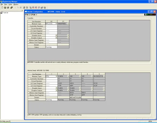
Enter Transmission Parameters
In Transmission Parameters, enter the MP2300S IP address, Subnet Mask, and Gateway IP. In Connection Parameter, set CNO-1 as follows: Local Port =502, Node IP Address =000.000.000.000, Node Port =00000, Connect Type =TCP, Protocol Type =MEMOBUS, Code =RTU.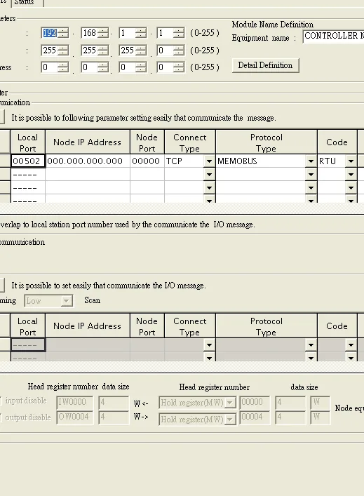
Configure MECHATROLINK as Master
Click MECHATROLINK to set up the MP2300S PLC as Master.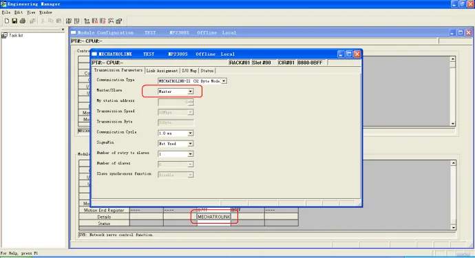
Save Configuration
Close all dialogs and save the configuration to the MP2300S.
NOTE: Only CNO 01 can auto-communicate with one HMI. Other CNO connections require a ladder program created for communication.
NOTE: DIP SW2-2 of MP2300S must be set to the OFF position during normal communication. If set to ON, the IP address will be erased after a power reset and communication with the HMI will fail.
Device Address
| Bit/Word | Device Type | Format | Range | Memo |
|---|---|---|---|---|
| B | MB_1 | DDDDh | 0 ~ 9999f | MB 0 ~ 9999 |
| B | MB_2 | DDDDDh | 100000 ~ 65534f | MB 10000 ~ 65535 |
| B | IB | HHHHH | 0 ~ a7ff0 | Read only |
| B | IW_Bit | HHHHdd | 0 ~ a7ff15 | |
| W | IW | HHHH | 0 ~ a7ff | Read only |
| DW | IL | HHHH | 0 ~ a7ff | Read only |
| DW (F) | IF | HHHH | 0 ~ a7ff | Read only |
| W | MW | DDDDD | 0 ~ 65534 | Holding register |
| DW | ML | DDDDD | 0 ~ 65533 | Double word |
| DW (F) | MF | DDDDD | 0 ~ 65533 | Floating point |
NOTE: When connecting via Ethernet interface, the maximum range of IW, IL, and IF is restricted.
Wiring Diagrams
NOTE: The serial port pin assignments may vary between HMI models.
Diagram 1: RS-232
| HMI | Direction | PLC |
|---|---|---|
| Pin assignments | RS232 9P D-Sub Male | |
| Rx | ↔ (bidirectional) | 2 TX |
| Tx | ↔ (bidirectional) | 3 RX |
| GND | ↔ (bidirectional) | 7 GND |
Diagram 2: RS-485 2W
| HMI | Direction | PLC |
|---|---|---|
| Pin assignments | 217IF-01 RS485 14P Connector | |
| Data- | ↔ (bidirectional) | 2, 4 D- |
| Data+ | ↔ (bidirectional) | 1, 3 D+ |
| GND | ↔ (bidirectional) | 14 GND |
Diagram 3: RS-485 4W
| HMI | Direction | PLC |
|---|---|---|
| Pin assignments | 217IF-01 RS422 14P Connector | |
| Rx- | ↔ (bidirectional) | 2 TXD- |
| RX+ | ↔ (bidirectional) | 1 TXD+ |
| Tx- | ↔ (bidirectional) | 4 RXD- |
| Tx+ | ↔ (bidirectional) | 3 RXD+ |
| GND | ↔ (bidirectional) | 14 GND |
Diagram 4: Ethernet
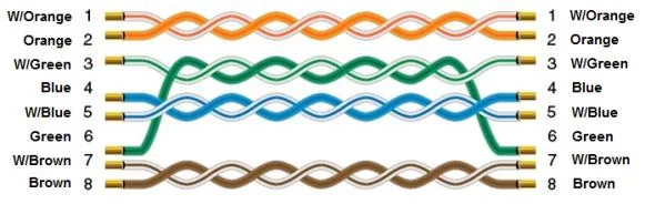
Use a standard straight-through (patch) Ethernet cable.