Introduction
All Maple Systems HMIs programmed with EBPro (EasyBuilder Pro), including every cMT X Series and cMT Series model, are compatible with a Yaskawa Electric DX100/DX200/FS100/YRC1000 Robot Controller (Ethernet). Configure your Controller and HMI/cMT with the following parameters to establish reliable communication.
Supported Series: YASKAWA controller type DX100, FS100, DX200, YRC1000, YRC100micro
Website: www.yaskawa.com
HMI Settings
| Parameters | Recommended | Options | Notes |
|---|---|---|---|
| PLC type | YASKAWA DX100/DX200/FS100/YRC1000 Robot Controller (Ethernet) | ||
| PLC I/F | Ethernet (UDP) | ||
| Port no. | 10040 | ||
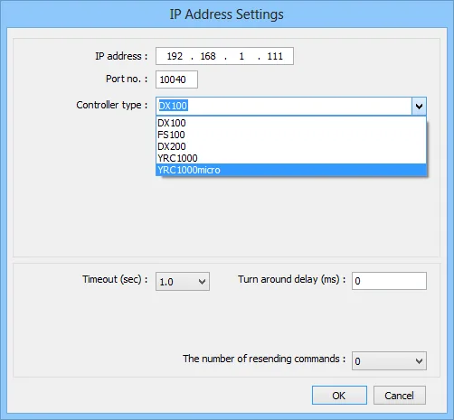
| Controller type | DX100 | DX100, FS100, DX200, YRC1000, YRC1000micro |
The address settings may vary according to the controller type selected. Taking DX200 as an example, after selecting it as the controller, the settings window below opens. In this window, users may select the Command first, then select the appropriate Instance and Attribute to complete the address setting. Command stands for address type, Instance stands for the content of the Command, and Attribute stands for the attribute of the Instance. Instance and Attribute may have further settings to complete.
Address Setting Examples
Example 1
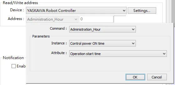
As shown in the settings below, the Command is Administration_Hour, which is used to “Control power ON time”, and its attribute is “Operation start time”.
Example 2
As shown in the settings below, the Command is Axis_Composition, which uses R1 of “Robot (Cartesian coordinate)”, and its attribute is “Axis name of the first axis”.
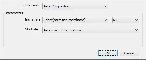
After setting, the following result is shown. The number shown near the Address drop-down list is automatically generated and cannot be changed by users.

Address Parameters
1. Command: Administration_Hour
Function: Management Time Acquiring Command (0x88)
Instances (DX100/FS100/DX200/YRC1000):
| Instance | Sub Instance | Details |
|---|---|---|
| Control power ON time | ||
| Servo power ON time | (TOTAL) | |
| (R1 to R8) | ||
| (S1 to S24) | ||
| Play back time | (TOTAL) | |
| (R1 to R8) | ||
| (S1 to S24) | ||
| Motion time | (TOTAL) | |
| (R1 to R8) | ||
| (S1 to S24) | ||
| Operation time | (application 1 to 8) |
Instances (YRC1000micro):
| Instance | Sub Instance | Details |
|---|---|---|
| Control power ON time | ||
| Servo power ON time | (TOTAL) | |
| (R1 to R2) | ||
| (S1 to S3) | ||
| Play back time | (TOTAL) | |
| (R1 to R2) | ||
| (S1 to S3) | ||
| Motion time | (TOTAL) | |
| (R1 to R2) | ||
| (S1 to S3) | ||
| Operation time | (application 1 to 2) |
Attributes:
| Attribute | Sub Attribute | Details |
|---|---|---|
| Operation start time | 8 Words — Ex. 2019/02/22 15:11 | |
| Elapse time | 6 Words — Ex. 000000:00’00 |
2. Command: Alarm
Function: Alarm Data Reading Command (0x70)
Instances:
| Instance | Details |
|---|---|
| The latest alarm | Up to four alarms are displayed on the P.P display at the same time |
| The second alarm from the latest | |
| The third alarm from the latest | |
| The fourth alarm from the latest |
Attributes:
| Attribute | Details |
|---|---|
| Alarm code | Range is from 0x0001 to 0x270F (decimal value: 1~9999) |
| Alarm data | Setting values vary in accordance with the contents of the alarm type. Also, some alarms are not displayed with the sub code. In this case, the value is zero (0x0). |
| By alarm type |
0 : No alarm 1 : Decimal UNSIGNED SHORT type (display example: [1]) 2 : UNSIGNED CHAR bit pattern (display example: [0000_0001]) 3 : User axis type (display example: [SLURBT]) 4 : Spacial coordinate type (display example: [XYZ]) 5 : Robot coordinate type (display example: [XYZRxRyRz]) 6 : Conveyor characteristic file (display example: [123]) 8 : Control group type (display example: [R1R2S1S2]) — robot & station 9 : Decimal SHORT type (display example: [-1]) 10 : UNSIGNED SHORT bit pattern (display example: [0000_0000_0000_0001]) 11 : Control group type (display example: [R1]) — for robot only 12 : Control group type (display example: [R1S1B1]) — for robot, station and base 20 : Control group LOW/HIGH logical axis (display example: [R1:LOW SLURBT, HIGH SLURBT]) 21 : Control group MIN/MAX logical axis (display example: [R1: MIN SLURBT, MAX SLURBT]) 22 : Control group MIN/MAX spacial coordinate (display example: [R1: MIN XYZ, MAX XYZ]) 23 : Logical axis of both control group 1 and control group 2 (display example: [R1: SLURBT, R2: SLURBT]) 24 : Logical axis 1 and 2 of the control group (display example: [R1: SLURBT, SLURBT]) 25 : Logical axis of the control group and UNSIGNED CHAR type (display example: [R1: SLURBT, 1]) 27 : Control group and UNSIGNED CHAR type (display example: [R1: 1]) |
| Alarm occurring time | 8 Words |
| Alarm character string name | 16 Words |
3. Command: Alarm_Detailed
Function: Alarm Data Reading Command (0x30A)
Instances:
| Instance | Details |
|---|---|
| The latest alarm | Up to four alarms are displayed on the P.P display at the same time. Specify one out of them. |
| The second alarm from the latest | Up to four alarms are displayed on the P.P display at the same time. Specify one out of them. |
| The third alarm from the latest | Up to four alarms are displayed on the P.P display at the same time. Specify one out of them. |
| The fourth alarm from the latest | Up to four alarms are displayed on the P.P display at the same time. Specify one out of them. |
Attributes:
| Attribute | Details |
|---|---|
| Alarm code | Range is from 0x0001 to 0x270F (decimal value: 0~9999) |
| Alarm data | Setting values vary in accordance with the contents of the alarm type. Also, some alarms are not displayed with the sub code. In this case, the value is zero (0x0). |
| By alarm type |
0 : No alarm 1 : Decimal UNSIGNED SHORT type (display example: [1]) 2 : UNSIGNED CHAR bit pattern (display example: [0000_0001]) 3 : User axis type (display example: [SLURBT]) 4 : Spacial coordinate type (display example: [XYZ]) 5 : Robot coordinate type (display example: [XYZRxRyRz]) 6 : Conveyor characteristic file (display example: [123]) 8 : Control group type (display example: [R1R2S1S2]) — robot & station 9 : Decimal SHORT type (display example: [-1]) 10 : UNSIGNED SHORT bit pattern (display example: [0000_0000_0000_0001]) 11 : Control group type (display example: [R1]) — for robot only 12 : Control group type (display example: [R1S1B1]) — for robot, station and base 20 : Control group LOW/HIGH logical axis (display example: [R1:LOW SLURBT, HIGH SLURBT]) 21 : Control group MIN/MAX logical axis (display example: [R1: MIN SLURBT, MAX SLURBT]) 22 : Control group MIN/MAX spacial coordinate (display example: [R1: MIN XYZ, MAX XYZ]) 23 : Logical axis of both control group 1 and control group 2 (display example: [R1: SLURBT, R2: SLURBT]) 24 : Logical axis 1 and 2 of the control group (display example: [R1: SLURBT, SLURBT]) 25 : Logical axis of the control group and UNSIGNED CHAR type (display example: [R1: SLURBT, 1]) 27 : Control group and UNSIGNED CHAR type (display example: [R1: 1]) |
| Alarm occurring time | 8 Words |
| Alarm character string name | 16 Words |
| Sub code data additional information character strings | 8 Words |
| Sub code data character strings | 48 Words |
| Sub code data character strings reverse display information | 48 Words |
4. Command: Alarm_History
Function: Alarm History Reading Command (0x71)
Instances:
| Instance | Sub Instance | Details |
|---|---|---|
| Major failure | ||
| Monitor alarm | ||
| User alarm | system | |
| user | ||
| OFF line alarm |
Attributes:
| Attribute | Details |
|---|---|
| Alarm code | Range is from 0x0001 to 0x270F (decimal value: 9999) |
| Alarm data | Setting values vary in accordance with the contents of the alarm type. Also, some alarms are not displayed with the sub code. In this case, the value is zero (0x0). |
| Alarm type |
0 : No alarm 1 : Decimal UNSIGNED SHORT type (display example: [1]) 2 : UNSIGNED CHAR bit pattern (display example: [0000_0001]) 3 : User axis type (display example: [SLURBT]) 4 : Spacial coordinate type (display example: [XYZ]) 5 : Robot coordinate type (display example: [XYZRxRyRz]) 6 : Conveyor characteristic file (display example: [123]) 8 : Control group type (display example: [R1R2S1S2]) — robot & station 9 : Decimal SHORT type (display example: [-1]) 10 : UNSIGNED SHORT bit pattern (display example: [0000_0000_0000_0001]) 11 : Control group type (display example: [R1]) — for robot only 12 : Control group type (display example: [R1S1B1]) — for robot, station and base 20 : Control group LOW/HIGH logical axis (display example: [R1: LOW SLURBT, HIGH SLURBT]) 21 : Control group MIN/MAX logical axis (display example: [R1: MIN SLURBT, MAX SLURBT]) 22 : Control group MIN/MAX spacial coordinate (display example: [R1: MIN XYZ, MAX XYZ]) 23 : Logical axis of both control group 1 and control group 2 (display example: [R1: SLURBT, R2: SLURBT]) 24 : Logical axis 1 and 2 of the control group (display example: [R1: SLURBT, SLURBT]) 25 : Logical axis of the control group and UNSIGNED CHAR type (display example: [R1: SLURBT, 1]) 27 : Control group and UNSIGNED CHAR type (display example: [R: 1]) |
| Alarm occurring time | 8 Words |
| Alarm character strings name | 16 Words |
5. Command: Alarm_History_Detailed
Function: Alarm History Reading Command (0x30B)
Instances:
| Instance | Sub Instance | Details |
|---|---|---|
| Major failure | ||
| Monitor alarm | ||
| User alarm | System | |
| User | ||
| OFF line alarm |
Attributes:
| Attribute | Details |
|---|---|
| Alarm code | Range is from 0x0001 to 0x270F (decimal value: 9999) |
| Alarm data | Setting values vary in accordance with the contents of the alarm type. Also, some alarms are not displayed with the sub code. In this case, the value is zero (0x0). |
| Alarm type |
0 : No alarm 1 : Decimal UNSIGNED SHORT type (display example: [1]) 2 : UNSIGNED CHAR bit pattern (display example: [0000_0001]) 3 : User axis type (display example: [SLURBT]) 4 : Spacial coordinate type (display example: [XYZ]) 5 : Robot coordinate type (display example: [XYZRxRyRz]) 6 : Conveyor characteristic file (display example: [123]) 8 : Control group type (display example: [R1R2S1S2]) — robot & station 9 : Decimal SHORT type (display example: [-1]) 10 : UNSIGNED SHORT bit pattern (display example: [0000_0000_0000_0001]) 11 : Control group type (display example: [R1]) — for robot only 12 : Control group type (display example: [R1S1B1]) — for robot, station and base 20 : Control group LOW/HIGH logical axis (display example: [R1:LOW SLURBT, HIGH SLURBT]) 21 : Control group MIN/MAX logical axis (display example: [R1: MIN SLURBT, MAX SLURBT]) 22 : Control group MIN/MAX spacial coordinate (display example: [R1: MIN XYZ, MAX XYZ]) 23 : Logical axis of both control group 1 and control group 2 (display example: [R1: SLURBT, R2: SLURBT]) 24 : Logical axis 1 and 2 of the control group (display example: [R1: SLURBT, SLURBT]) 25 : Logical axis of the control group and UNSIGNED CHAR type (display example: [R1: SLURBT, 1]) 27 : Control group and UNSIGNED CHAR type (display example: [R1: 1]) |
| Alarm occurring time | 8 Words |
| Alarm character strings name | 16 Words |
| Sub code data additional information character strings | 8 Words |
| Sub code data character strings | 48 Words |
| Sub code data character strings reverse display information | 48 Words |
6. Command: Axis_Composition
Function: Axis Configuration Information Reading Command (0x74)
Instances (DX100/FS100/DX200/YRC1000):
| Instance | Sub Instance | Details |
|---|---|---|
| Robot (pulse value) | R1~R8 | |
| Base (pulse value) | B1~B8 | |
| Station (pulse value) | S1~S24 | |
| Robot (cartesian coordinate) | R1~R8 | |
| Base (cartesian coordinate) | B1~B8 |
Instances (YRC1000micro):
| Instance | Sub Instance | Details |
|---|---|---|
| Robot (pulse value) | R1~R2 | |
| Base (pulse value) | B1~B2 | |
| Station (pulse value) | S1~S3 | |
| Robot (cartesian coordinate) | R1~R2 | |
| Base (cartesian coordinate) | B1~B2 |
Attributes:
| Attribute | Details |
|---|---|
| First coordinate name | 2 Words |
| Second coordinate name | |
| Third coordinate name | |
| Fourth coordinate name | |
| Fifth coordinate name | |
| Sixth coordinate name | |
| Seventh coordinate name | |
| Eighth coordinate name |
7. Command: B
Function: Byte Variable (B) Reading / Writing Command (0x7A) — Data type: 8 bit
Instances:
| Instance | Sub Instance | Details |
|---|---|---|
| 0~99 |
Attributes: (none)
8. Command: BP
Function: Base Position Type Variable (Bp) Reading / Writing Command (0x80)
Instances:
| Instance | Sub Instance | Details |
|---|---|---|
| 0~127 |
Attributes:
| Attribute | Details |
|---|---|
| Data type | 0 : Pulse value / 16 : Base coordinated value |
| Coordinated data of the first axis | 2 Words |
| Coordinated data of the second axis | |
| Coordinated data of the third axis | |
| Coordinated data of the fourth axis | |
| Coordinated data of the fifth axis | |
| Coordinated data of the sixth axis | |
| Coordinated data of the seventh axis | |
| Coordinated data of the eighth axis |
9. Command: D
Function: Double Precision Integer Type Variable (D) Reading / Writing Command (0x7C) — Data type: 32 bit
Instances:
| Instance | Sub Instance | Details |
|---|---|---|
| 0~99 |
Attributes: (none)
10. Command: Axis_Position_Deflection
Function: Position Error Reading Command (0x76)
Instances (DX100/FS100/DX200/YRC1000):
| Instance | Sub Instance | Details |
|---|---|---|
| Robot axis | R1~R8 | |
| Base axis | B1~B8 | |
| Station axis | S1~S24 |
Instances (YRC1000micro):
| Instance | Sub Instance | Details |
|---|---|---|
| Robot axis | R1~R2 | |
| Base axis | B1~B2 | |
| Station axis | S1~S3 |
Attributes:
| Attribute | Details |
|---|---|
| First axis data | Position variable data of each axis can be read out |
| Second axis data | |
| Third axis data | |
| Fourth axis data | |
| Fifth axis data | |
| Sixth axis data | |
| Seventh axis data | |
| Eighth axis data |
11. Command: Each_Shaft_Torque
Function: Torque Data Reading Command (0x77)
Instances (DX100/FS100/DX200/YRC1000):
| Instance | Sub Instance | Details |
|---|---|---|
| Robot axis | R1~R8 | |
| Base axis | B1~B8 | |
| Station axis | S1~S24 |
Instances (YRC1000micro):
| Instance | Sub Instance | Details |
|---|---|---|
| Robot axis | R1~R2 | |
| Base axis | B1~B2 | |
| Station axis | S1~S3 |
Attributes:
| Attribute | Details |
|---|---|
| First axis data | Torque data of each axis can be read out |
| Second axis data | |
| Third axis data | |
| Fourth axis data | |
| Fifth axis data | |
| Sixth axis data | |
| Seventh axis data | |
| Eighth axis data |
12. Command: EX
Function: External Axis Type Variable (Ex) Reading / Writing Command (0x81) — Data type: 32 bit
Instances:
| Instance | Sub Instance | Details |
|---|---|---|
| 0~127 |
Attributes:
| Attribute | Details |
|---|---|
| Data type | 0 : Pulse value |
| Coordinated data of the first axis | |
| Coordinated data of the second axis | |
| Coordinated data of the third axis | |
| Coordinated data of the fourth axis | |
| Coordinated data of the fifth axis | |
| Coordinated data of the sixth axis | |
| Coordinated data of the seventh axis | |
| Coordinated data of the eighth axis |
13. Command: I
Function: Integer Type Variable (I) Reading / Writing Command (0x7B) — Data type: 16 bit
Instances:
| Instance | Details |
|---|---|
| 0~99 |
Attributes: (none)
14. Command: IO_Data
Function: I/O Data Reading / Writing Command (0x78) — Data type: 8 bit
Instances:
| Instance | Details |
|---|---|
| Robot user input signal | |
| Robot user output signal | |
| External input signal | |
| Network input signal | Only network input signal is writable |
| External output signal | |
| Network output signal | |
| Robot system input signal | |
| Robot system output signal | |
| Interface panel input signal | |
| Auxiliary relay signal | |
| Robot control status signal | |
| Pseudo input signal |
Attributes: (none)
15. Command: Job_Information
Function: Executing Job Information Reading Command (0x73)
Instances:
| Instance | Details |
|---|---|
| Master task | |
| Sub task 1~15 |
Attributes:
| Attribute | Details |
|---|---|
| Job name | 16 Words |
| Line number | 0~9999 |
| Step number | 1~9998 |
| Speed override value |
16. Command: Job_Select
Function: Job Select Command (0x87)
Instances:
| Instance | Details |
|---|---|
| Set the executing job | |
| Set the master job (task 0~15) |
Attributes:
| Attribute | Details |
|---|---|
| Job name | 16 Words |
| Line number | 2 Words (0~9999) |
NOTE: 16 words job name + 2 words line number = 18 words must be written together.
17. Command: On_Off
Write only — 1 = ON, 2 = OFF
Function: Hold / Servo On/Off Command (0x83)
Instances:
| Instance | Details |
|---|---|
| HOLD | |
| Servo ON | |
| HLOCK |
Attributes: (none)
18. Command: P
Function: Robot Position Type Variable (P) Reading / Writing Command (0x7F)
Instances:
| Instance | Sub Instance | Details |
|---|---|---|
| 0~127 |
Attributes:
| Attribute | Details |
|---|---|
| Data type | 0 : Pulse value / 16 : Base coordinated value / 17 : Robot coordinated value / 18 : User coordinated value / 19 : Tool coordinated value |
| Form | For the form, refer to “Details of data”. |
| Tool number | |
| User coordinate number | |
| Extended form | For the extended form, refer to “Details of data”. |
| Coordinated data of the first axis | |
| Coordinated data of the second axis | |
| Coordinated data of the third axis | |
| Coordinated data of the fourth axis | |
| Coordinated data of the fifth axis | |
| Coordinated data of the sixth axis | |
| Coordinated data of the seventh axis | |
| Coordinated data of the eighth axis |
Details of data: Form
| Bit | Value 0 | Value 1 |
|---|---|---|
| Bit0 | Front | Back |
| Bit1 | Upper arm | Lower arm |
| Bit2 | Flip | No flip |
| Bit3 | θR < 180 | θR ≥ 180 |
| Bit4 | θT < 180 | θT ≥ 180 |
| Bit5 | θS < 180 | θS ≥ 180 |
| Bit6 | Redundant front | Redundant back |
| Bit7 | Previous step regarded | Form regarded reverse |
Details of data: Extend Form
| Bit | Value 0 | Value 1 |
|---|---|---|
| Bit0 | θL < 180 | θL ≥ 180 |
| Bit1 | θU < 180 | θU ≥ 180 |
| Bit2 | θB < 180 | θB ≥ 180 |
| Bit3 | θE < 180 | θE ≥ 180 |
| Bit4 | θW < 180 | θW ≥ 180 |
| Bit5 | Reserve | |
| Bit6 | ||
| Bit7 |
19. Command: R
Function: Real Type Variable (R) Reading / Writing Command (0x7D) — 32 bit data
Instances:
| Instance | Sub Instance | Details |
|---|---|---|
| 0~99 |
Attributes: (none)
20. Command: Register_Data
Function: Register Data Reading / Writing Command (0x79) — 16 bit data
Instances:
| Instance | Sub Instance | Details |
|---|---|---|
| 0~999 |
Attributes: (none)
21. Command: Reset_Cancellation
Write only — write 1 to reset
Function: Alarm Reset / Error Cancel Command (0x82)
Instances:
| Instance | Details |
|---|---|
| Resetting of alarm | |
| Cancelling of error |
Attributes: (none)
22. Command: Robot_Position
Function: Robot Position Data Reading Command (0x75)
Instances (DX100/FS100/DX200/YRC1000):
| Instance | Sub Instance | Details |
|---|---|---|
| Robot (pulse value) | R1~R8 | |
| Base (pulse value) | B1~B8 | |
| Station (pulse value) | S1~S24 | |
| Robot (cartesian coordinate) | R1~R8 |
Instances (YRC1000micro):
| Instance | Sub Instance | Details |
|---|---|---|
| Robot (pulse value) | R1~R2 | |
| Base (pulse value) | B1~B2 | |
| Station (pulse value) | S1~S3 | |
| Robot (cartesian coordinate) | R1~R2 |
Attributes:
| Attribute | Details |
|---|---|
| Data type | 0 : pulse value / 16 : base coordinate value |
| Form | For the form, refer to “Details of data”. |
| Tool number | |
| User coordinate number | |
| Extended form | For the extended form, refer to “Details of data”. |
| First axis data | |
| Second axis data | |
| Third axis data | |
| Fourth axis data | |
| Fifth axis data | |
| Sixth axis data | |
| Seventh axis data | |
| Eighth axis data |
Details of data: Form
| Bit | Value 0 | Value 1 |
|---|---|---|
| Bit0 | Front | Back |
| Bit1 | Upper arm | Lower arm |
| Bit2 | Flip | No flip |
| Bit3 | θR < 180 | θR ≥ 180 |
| Bit4 | θT < 180 | θT ≥ 180 |
| Bit5 | θS < 180 | θS ≥ 180 |
| Bit6 | Redundant front | Redundant back |
| Bit7 | Previous step regarded reverse conversion specified | Form regarded reverse conversion specified |
Details of data: Extend Form
| Bit | Value 0 | Value 1 |
|---|---|---|
| Bit0 | θL < 180 | θL ≥ 180 |
| Bit1 | θU < 180 | θU ≥ 180 |
| Bit2 | θB < 180 | θB ≥ 180 |
| Bit3 | θE < 180 | θE ≥ 180 |
| Bit4 | θW < 180 | θW ≥ 180 |
| Bit5 | Reserve | |
| Bit6 | ||
| Bit7 |
23. Command: S
Function: 16 Byte Character Type Variable (S) Reading / Writing Command (0x7E) — 8 Words
Instances:
| Instance | Sub Instance | Details |
|---|---|---|
| 0~99 |
Attributes: (none)
24. Command: Start
Write only — write 1 to start
Function: Start-up (Job Start) Command (0x86)
25. Command: State_Switch
Write only — 1 : STEP / 2 : 1 CYCLE / 3 : CONTINUE
Function: Step / Cycle / Continuous Switching Command (0x84)
26. Command: Status
Function: Status Information Reading Command (0x72)
Attributes:
| Attribute | Details |
|---|---|
| Data 1 | Specify the status data number. For the details of Data 1 and Data 2, refer to “Details of data”. |
| Data 2 |
Details of data: Data 1
| Bit | Details |
|---|---|
| Bit0 | Step |
| Bit1 | 1 cycle |
| Bit2 | Automatic and continuous |
| Bit3 | Running |
| Bit4 | In-guard safe operation |
| Bit5 | Teach |
| Bit6 | Play |
| Bit7 | Command remote |
Details of data: Data 2
| Bit | Details |
|---|---|
| Bit0 | |
| Bit1 | In hold status (by programming pendant) |
| Bit2 | In hold status (externally) |
| Bit3 | In hold status (by command) |
| Bit4 | Alarming |
| Bit5 | Error occurring |
| Bit6 | Servo ON |
| Bit7 |
27. Command: String_Display_To_Pendant
Write only — 15 words
Function: Character String Display Command To The Programming Pendant (0x85)
28. Command: System_Information
Function: System Information Acquiring Command (0x89)
Instances (DX100/FS100/DX200/YRC1000):
| Instance | Sub Instance | Details |
|---|---|---|
| Type information | R1~R8 | |
| Type information | S1~S24 | |
| Application information | 1~8 |
Instances (YRC1000micro):
| Instance | Sub Instance | Details |
|---|---|---|
| Type information | R1~R2 | |
| Type information | S1~S3 | |
| Application information | 1~2 |
Attributes:
| Attribute | Details |
|---|---|
| System software version | 12 Words |
| Model name / application | 8 Words |
| Parameter version | 4 Words |
29. Command: S_32BYTE
Function: 32 Byte Character Type Variable (S) Reading / Writing Command (0x8E) — 16 words
Instances:
| Instance | Sub Instance | Details |
|---|---|---|
| 0~99 |
30. Command: Move_Instruction_Cartesian
Write only — data must be written all at once.
Function: Move Instruction Command (Type Cartesian coordinates) (0x8A)
Instances:
| Instance | Details |
|---|---|
| Link absolute position operation | |
| Straight absolute position operation | |
| Straight increment value operation |
Data:
| Data | Details |
|---|---|
| Specifying control group (Robot) | 1 to 8 (Robot No.) |
| Specifying control group (Station) | 1 to 24 (Station No.) |
| Specifying the classification in speed | Specify the classification of operations: 0 : % (Link operation) / 1 : V (Cartesian operation) / 2 : VR (Cartesian operation) |
| Specifying a speed | Specify the rate — Link operation : 0.01% / Cartesian operation V speed : 0.1 mm/s / Cartesian operation VR speed : 0.1 degree/s |
| Specifying the operation coordinate | 16 : Base coordinate / 17 : Robot coordinate / 18 : User coordinate / 19 : Tool coordinate |
| X coordinate value | |
| Y coordinate value | |
| Z coordinate value | |
| Tx coordinate value | unit: 0.0001 degree |
| Ty coordinate value | unit: 0.0001 degree |
| Tz coordinate value | unit: 0.0001 degree |
| Reservation | |
| Reservation | Only supported in YRC1000micro |
| Type | Refer to “Details of data” below |
| Expanded type | |
| Tool No. | 0 to 63 |
| User coordinate No. | 1 to 63 |
| Base 1st axis position | |
| Base 2nd axis position | |
| Base 3rd axis position | |
| Station 1st axis position | |
| Station 2nd axis position | |
| Station 3rd axis position | |
| Station 4th axis position | |
| Station 5th axis position | |
| Station 6th axis position |
Details of data: Form
| Bit | Value 0 | Value 1 |
|---|---|---|
| Bit0 | Front | Back |
| Bit1 | Upper arm | Lower arm |
| Bit2 | Flip | No flip |
| Bit3 | θR < 180 | θR ≥ 180 |
| Bit4 | θT < 180 | θT ≥ 180 |
| Bit5 | θS < 180 | θS ≥ 180 |
| Bit6 | Reserve | |
| Bit7 |
Details of data: Extend Form
| Bit | Value 0 | Value 1 |
|---|---|---|
| Bit0 | θL < 180 | θL ≥ 180 |
| Bit1 | θU < 180 | θU ≥ 180 |
| Bit2 | θB < 180 | θB ≥ 180 |
| Bit3 | θE < 180 | θE ≥ 180 |
| Bit4 | θW < 180 | θW ≥ 180 |
| Bit5 | Reserve | |
| Bit6 | ||
| Bit7 |
31. Command: Move_Instruction_Pulse
Write only — data must be written all at once.
Function: Move Instruction Command (Type Pulse) (0x8B)
Instances:
| Instance | Details |
|---|---|
| Link absolute position operation | |
| Straight absolute position operation |
Data:
| Data | Details |
|---|---|
| Specifying control group (Robot) | 1 to 8 (Robot No.) |
| Specifying control group (Station) | 1 to 24 (Station No.) |
| Specifying the classification in speed | Specify the classification of operations: 0 : % (Link operation) / 1 : V (Cartesian operation) / 2 : VR (Cartesian operation) |
| Specifying a speed | Specify the rate — Link operation : 0.01% / Cartesian operation V speed : 0.1 mm/s / Cartesian operation VR speed : 0.1 degree/s |
| Robot 1st axis pulse value | |
| Robot 2nd axis pulse value | |
| Robot 3rd axis pulse value | |
| Robot 4th axis pulse value | |
| Robot 5th axis pulse value | |
| Robot 6th axis pulse value | |
| Robot 7th axis pulse value | |
| Robot 8th axis pulse value | |
| Tool No. | 0 to 63 |
| Base 1st axis position (pulse value) | Up to three axes |
| Base 2nd axis position (pulse value) | |
| Base 3rd axis position (pulse value) | |
| Station 1st axis position (pulse value) | |
| Station 2nd axis position (pulse value) | |
| Station 3rd axis position (pulse value) | |
| Station 4th axis position (pulse value) | |
| Station 5th axis position (pulse value) | |
| Station 6th axis position (pulse value) |
Device Address
| Bit/Word | Device type (Command) | Format | Range |
|---|---|---|---|
| B | Status_Bit | DDDDDDDdd | 0 ~ 163836331 |
| B | Robot_Position_Bit | DDDDDDDdd | 0 ~ 163836331 |
| B | IO_Data_Bit | DDDDDo | 0 ~ 163837 |
| B | Register_Data_Bit | DDDDDdd | 0 ~ 1638315 |
| B | B_Bit | DDDDDo | 0 ~ 163837 |
| B | I_Bit | DDDDDdd | 0 ~ 1638315 |
| B | D_Bit | DDDDDdd | 0 ~ 1638331 |
| B | R_Bit | DDDDDdd | 0 ~ 1638331 |
| B | P_Bit | DDDDDDDdd | 0 ~ 163836331 |
| W | Administration_Hour | DDDDDDDDD | 0 ~ 163836300 |
| W | Alarm | DDDDDDDDD | 0 ~ 163836300 |
| W | Alarm_Detailed | DDDDDDDDD | 0 ~ 163836300 |
| W | Alarm_History | DDDDDDDDD | 0 ~ 163836300 |
| W | Alarm_History_Detailed | DDDDDDDDD | 0 ~ 163836300 |
| W | Axis_Composition | DDDDDDDDD | 0 ~ 163836300 |
| W | B | DDDDD | 0 ~ 16383 |
| W | BP | DDDDDDD | 0 ~ 163363 |
| W | D | DDDDD | 0 ~ 16383 |
| W | Axis_Position_Deflection | DDDDDDD | 0 ~ 1638363 |
| W | Each_Shaft_Torque | DDDDDDD | 0 ~ 1638363 |
| W | EX | DDDDDDD | 0 ~ 1638363 |
| W | I | DDDDD | 0 ~ 16383 |
| W | IO_Data | DDDDD | 0 ~ 16383 |
| W | Job_Information | DDDDDDDDD | 0 ~ 163836300 |
| W | Job_Select | DDDDDDDDD | 0 ~ 163836300 |
| W | On_Off | DDDDD | 0 ~ 16383 |
| W | P | DDDDDDD | 0 ~ 1638363 |
| W | R | DDDDD | 0 ~ 16383 |
| W | Register_Data | DDDDD | 0 ~ 16383 |
| W | Reset_Cancellation | DDDDD | 0 ~ 16383 |
| W | Robot_Position | DDDDDDD | 0 ~ 1638363 |
| W | S | DDDDDDD | 0 ~ 1638300 |
| W | Start | DDDDDDD | 0 ~ 1638363 |
| W | State_Switch | DDDDD | 0 ~ 16383 |
| W | DDDDDDD | 0 ~ 1638363 | Status |
| W | String_Display_To_Pendant | DDDDDDD | 0 ~ 1638300 |
| W | System_Information | DDDDDDDDD | 0 ~ 163836300 |
| W | S_32BYTE | DDDDDDD | 0 ~ 1638300 |
| W | Move_Instruction_Cartesian | DDDDDDD | 0 ~ 1638300 |
| W | Move_Instruction_Pulse | DDDDDDD | 0 ~ 1638300 |
Wiring Diagram
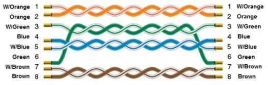
NOTE: Use a straight-through Ethernet cable (CAT5e or higher) to connect the HMI to the Yaskawa robot controller.
The diagram below shows the Ethernet cable wiring.