
Introduction
All Maple Systems HMIs programmed with EBPro (EasyBuilder Pro), including every cMT X Series and cMT Series model, are compatible with Panasonic MINAS A5. Configure your Controller and HMI/cMT with the following parameters to establish reliable communication.
Supported Series: Panasonic MINAS A5 series Servo Drive
HMI Settings
| Parameters | Recommended | Options | Notes |
|---|---|---|---|
| PLC type | Panasonic MINAS A5 | ||
| PLC I/F | RS232 | RS232/RS485 2W | |
| Baud rate | 9600 | 2400~115200 | |
| Data bits | 8 | ||
| Parity | None | ||
| Stop bits | 1 | ||
| Axis no. | 0 (master station only) | 0 ~ 127 (slave) |
NOTE: When connecting with more than two devices, it is recommended to set timeout to more than 4 seconds. Set a longer timeout when connecting with more devices to maintain good communication.
Device Address
| Bit/Word | Device type | Format | Range | Memo |
|---|---|---|---|---|
| B | Command 20 | D | 0 ~ 7 | States (Note 3) |
| B | Command 27 | DD | 0 ~ 31 | Input Signal (Note 3) |
| B | Command 28 | DD | 0 ~ 31 | Output Signal (Note 3) |
| W | Command 01 | D | 0 | CPU Version (Numeric format: 16-bit Hex) |
| W | Command 05 | DD | 0 ~ 11 | Driver Version (ASCII / 12 words) |
| W | Command 06 | DD | 0 ~ 11 | Motor Version (ASCII / 12 words) |
| W | Command 21 | D | 0 ~ 1 | command pulse counter (Numeric format: 32-bit Signed) |
| W | Command 22 | D | 0 ~ 1 | feedback pulse counter (Numeric format: 32-bit Signed) |
| W | Command 24 | D | 0 | present speed (Numeric format: 16-bit Unsigned) |
| W | Command 25 | D | 0 | present torque (Numeric format: 16-bit Unsigned) |
| W | Command 26 | D | 0 ~ 1 | present deviation counter (Numeric format: 32-bit Signed) |
| W | Command2D_S | D | 0 ~ 1 | Command 2D Single turn data (Numeric format: 32-bit Signed) |
| W | Command2D_M | D | 0 ~ 1 | Command 2D Multi-turn data (Numeric format: 32-bit Signed) |
| W | Parameter | HHH | 0 ~ 639 | Individual Parameter (range: 0x000 ~ 0x639) (Note 2) |
| W | Command 72 | D | 0 | write parameter to EEPROM (Note 1) |
| W | Command 90 | D | 0 | present Alarm Data (Numeric format: 16-bit Unsigned) |
| W | Command 92 | DD | 1 ~ 14 | Batch Alarm (Note 4) (Numeric format: 16-bit Unsigned) |
| W | Command 93 | D | 0 | clear Alarm History (include EEPROM) (Note 1) |
| W | Command 94 | D | 0 | Alarm Clear (Note 1) |
| W | Command 9B | D | 0 | Absolute Clear (Note 1) |
Command 72,Command 93,Command 94, andCommand 9Bare write only. (These commands are able to use Set Bit Object and execute the write command after triggering Set Bit Object.) Commands other than these four are read only.- Parameter read/write: Use device type to define address control from 000~639. For example: “address_000” is mapping to “Parameter_000”. (Please refer to Panasonic MINAS A5 Series User Manual.)
- Device address type can define MINAS A5 Driver’s command list.
Command 20,Command 27, andCommand 28are Bit type, use “Operating range” to map communication order status. For example: “Command 20_3” means “Read state_CCW”. (Please refer to Panasonic MINAS A5 Series User Manual.) Command 92is word type; use “Operating range” to map the record of 14 alarms.
Wiring Diagram
NOTE: The serial port pin assignments may vary between HMI models.
Diagram 1: RS-232 (MINAS A5 Driver X2 Port RS232 Signal)
The following is the view from the soldering point of a connector.
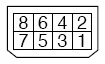
| HMI | Direction | PLC |
|---|---|---|
| Pin assignments | RS232 8P Connector |
|
| Rx | ↔ (bidirectional) | 3 TXD |
| Tx | ↔ (bidirectional) | 4 RXD |
| GND | ↔ (bidirectional) | 1 GND |
Diagram 2: RS-485 2W (MINAS A5 Driver X2 Port RS485 Signal)
The following is the view from the soldering point of a connector.
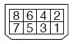
| HMI | Direction | PLC |
|---|---|---|
| Pin assignments | RS485 2W 8P Connector |
|
| Data- | ↔ (bidirectional) | 5,7 485- |
| Data+ | ↔ (bidirectional) | 6,8 485+ |
| GND | ↔ (bidirectional) | 1 GND |