Introduction
All Maple Systems HMIs programmed with EBPro (EasyBuilder Pro), including every cMT X Series and cMT Series model, are compatible with Panasonic MEWTOCOL7. Configure your Controller and HMI/cMT with the following parameters to establish reliable communication.
Supported Series: Panasonic GT series FP7
Website: pewa.panasonic.com
HMI Setting
| Parameters | Recommended | Options | Notes |
|---|---|---|---|
| PLC type | Panasonic MEWTOCOL7 | ||
| PLC I/F | RS232 / Ethernet | ||
| Baud rate | 9600 | 9600 ~ 115200 | |
| Data bits | 8 | 7, 8 | |
| Parity | Odd | Even, None, Odd | |
| Stop bits | 1 | 1, 2 | |
| PLC sta. no. | 1 | 1 ~ 256 | |
| Port no. | 60001 | 1 ~ 65535 |
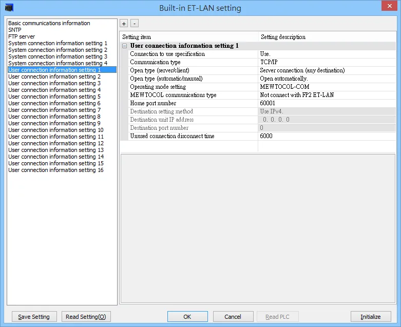
PLC Setting
| Parameter | Value |
|---|---|
| Communication type | TCP/IP |
| Open type | Server connection (any destination) |
| Operating mode setting | MEWTOCOL7-COM |
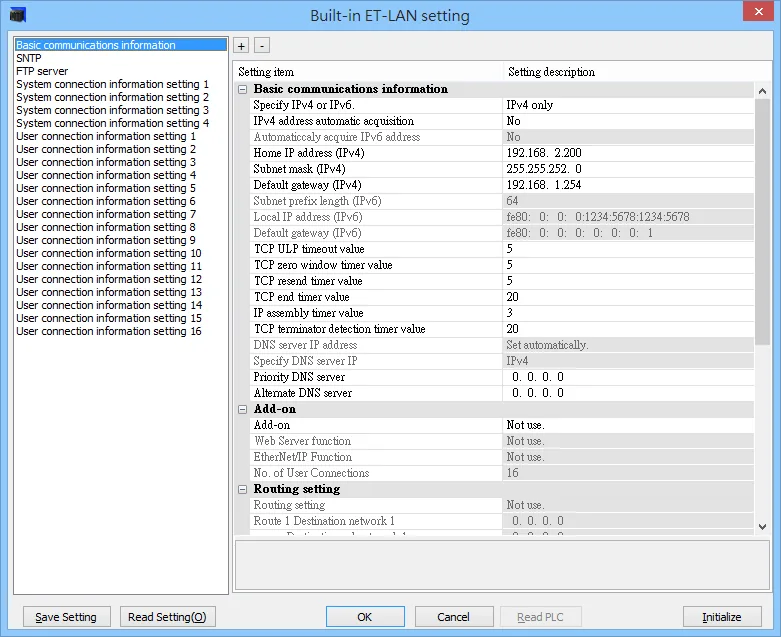
Built-in ET-LAN Setting
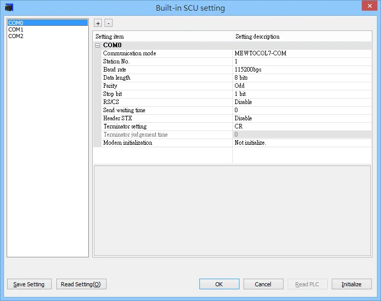
Built-in SCU Setting
Import Tag
Export CSV file from FPWIN Pro 7
In FPWIN Pro 7, go to Project → Export → Variables as CSV file → All project variables.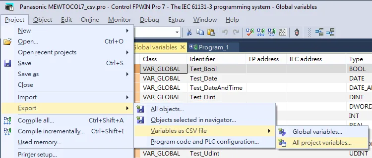
Import tags in EBPro (EasyBuilder Pro)
In EBPro (EasyBuilder Pro), go to System Parameter → Create new driver → Import Tags.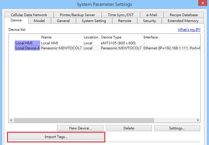
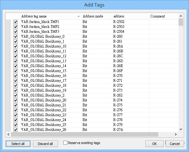
Device Address
| Bit/Word | Device type | Format | Range | Memo |
|---|---|---|---|---|
| B | X | DDDh | 0 ~ 511f | External input |
| B | Y | DDDh | 0 ~ 511f | External output |
| B | R | DDDDh | 0 ~ 2047f | Internal relay |
| B | L | DDDDh | 0 ~ 1023f | Link relay |
| B | T | DDDD | 0 ~ 4095 | Timer |
| B | C | DDDD | 0 ~ 1023 | Counter |
| B | P | DDDh | 0 ~ 255f | Pulse relay |
| B | E | DDDD | 0 ~ 4095 | Error notification relay |
| B | SR | DDDh | 0 ~ 223f | System relay |
| B | IN | SSDDh | 1000 ~ 9962f | Direct input *note1 |
| B | OT | SSDDh | 1000 ~ 9962f | Direct output *note1 |
| B | LD_Bit | DDDDD.h | 0 ~ 16383.f | LD bit specification |
| B | DT_Bit | DDDDDD.h | 0 ~ 999423.f | DT bit specification |
| B | UM_Bit | SSHHHHH.h | 0 ~ 997FFFF.f | UM bit specification *note1 |
| B | _X | LLLDDDh | 10000 ~ 999511f | External input *note2 |
| B | _Y | LLLDDDh | 10000 ~ 999511f | External output *note2 |
| B | _R | LLLDDDDh | 100000 ~ 9992047f | Internal relay *note2 |
| B | _L | LLLDDDDh | 100000 ~ 9991023f | Link relay *note2 |
| B | _T | LLLDDDD | 10000 ~ 9994095 | Timer *note2 |
| B | _C | LLLDDDD | 10000 ~ 9991023 | Counter *note2 |
| B | _P | LLLDDDh | 10000 ~ 999255f | Pulse relay *note2 |
| B | _LD_Bit | LLLDDDDD.h | 100000.0 ~ 9991633.f | LD bit specification *note2 |
| B | _DT_Bit | LLLDDDDDD.h | 1000000.0 ~ 999999423.f | DT bit specification *note2 |
| W | WX | DDD | 0 ~ 511 | External input word |
| W | WY | DDD | 0 ~ 511 | External output word |
| W | WR | DDDD | 0 ~ 2047 | Internal relay word |
| W | WL | DDDD | 0 ~ 1023 | Link relay word |
| W | WS | DDD | 0 ~ 223 | System relay word |
| W | LD | DDDDD | 0 ~ 16383 | Link register |
| W | DT | DDDDDD | 0 ~ 999423 | Data register |
| W | SD | DDD | 0 ~ 255 | System register |
| W | WI | SSDD | 100 ~ 9962 | Input register *note1 |
| W | WO | SSDD | 100 ~ 9962 | Output register *note1 |
| W | UM | SSHHHHH | 100000 ~ 997FFFF | Unit memory *note1 |
| DW | TS | DDDD | 0 ~ 4095 | Timer setting value |
| DW | TE | DDDD | 0 ~ 4095 | Timer elapsed value |
| DW | CS | DDDD | 0 ~ 1023 | Counter setting value |
| DW | CE | DDDD | 0 ~ 1023 | Counter elapsed value |
| DW | I | H | 0 ~ E | Index register |
| W | _WX | LLLDDD | 1000 ~ 999511 | External input word *note2 |
| W | _WY | LLLDDD | 1000 ~ 999511 | External output word *note2 |
| W | _WR | LLLDDDD | 10000 ~ 9992047 | Internal relay word *note2 |
| W | _WL | LLLDDDD | 10000 ~ 9991023 | Link relay word *note2 |
| W | _LD | LLLDDDDD | 100000 ~ 99916383 | Link register *note2 |
| W | _DT | LLLDDDDDD | 1000000 ~ 999999423 | Data register *note2 |
| DW | _TS | LLLDDDD | 10000 ~ 9994095 | Timer setting value *note2 |
| DW | _TE | LLLDDDD | 10000 ~ 9994095 | Timer elapsed value *note2 |
| DW | _CS | LLLDDDD | 10000 ~ 9991023 | Counter setting value *note2 |
| DW | _CE | LLLDDDD | 10000 ~ 9991023 | Counter elapsed value *note2 |
*note1 SS = Slot address (1~99)
*note2 LLL = Local address (Program block)
Wiring Diagram
NOTE: The serial port pin assignments may vary between HMI models.
Diagram 1: RS-232
| HMI | Direction | PLC |
|---|---|---|
| Pin assignments | RS232 Terminal | |
| Rx | ↔ (bidirectional) | SD |
| Tx | ↔ (bidirectional) | RD |
| GND | ↔ (bidirectional) | SG |
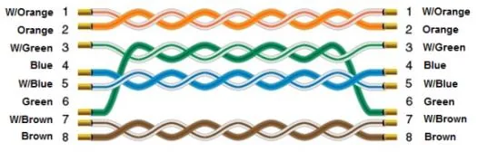
Diagram 2: Ethernet