
Introduction
All Maple Systems HMIs programmed with EBPro (EasyBuilder Pro), including every cMT X Series and cMT Series model, are compatible with VIPA 200/300 MPI. Configure your Controller and HMI/cMT with the following parameters to establish reliable communication.
HMI Settings
Communication Parameters
| Parameters | Recommended | Options | Notes |
|---|---|---|---|
| PLC type | VIPA 200/300 MPI | ||
| PLC I/F | RS-485 2W | ||
| Baud rate | 187.5K | Only HMI with a sticker “MPI 187.5K” on the rear cover supports MPI communication. | |
| Data bits | 8 | ||
| Parity | Even | ||
| Stop bits | 1 | ||
| PLC sta. no. | 2 | 2 ~ 31 | |
| Online simulator | NO | ||
| Extend address mode | Yes | ||
| Broadcast command | NO |
Device Address
| Bit/Word | Device Type | Format | Range | Memo |
|---|---|---|---|---|
| B | I | DDDDo | 0 ~ 40957 | Input (I) |
| B | Q | DDDDo | 0 ~ 40957 | Output (O) |
| B | M | DDDDo | 0 ~ 40957 | Bit Memory |
| B | DBnBit | FFFFDDDDo | 0 ~ 409699997 | Data Register Bit |
| B | DB0Bit ~ DB99Bit | DDDDDo | 0 ~ 655327 | Data Register Bit |
| W | IW | DDDD | 0 ~ 4095 | Input (I) |
| W | QW | DDDD | 0 ~ 4095 | Output (O) |
| W | MW | DDDD | 0 ~ 4095 | Bit Memory |
| DW | MD | DDDD | 0 ~ 4094 | |
| Byte | MB | DDDD | 0 ~ 4095 | Bit Memory Byte |
| Byte | DBBn | FFFFDDDD | 0 ~ 40969999 | Data Register |
| W | DBn | FFFFDDDD | 0 ~ 40969999 | Data Register (must be even) |
| DW | DBDn | FFFFDDDD | 0 ~ 40969999 | Data Register Double Word |
| W | DBn_String | FFFFDDDD | 0 ~ 40969999 | |
| DW | DBDn_String | FFFFDDDD | 0 ~ 40969999 | |
| W | DB0 ~ DB99 | DDDDD | 0 ~ 65532 | Data Register (must be even) |
* Double word and floating point value must use DBDn device type.
Multi-HMIs-Multi-PLCs Communication Setting
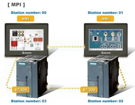
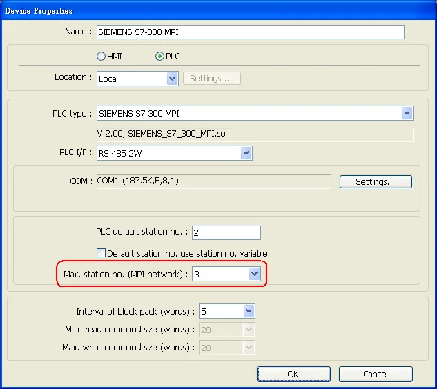
For the SIEMENS S7-300 MPI driver in Multi-HMIs-Multi-PLCs communication, the Max. station no. (MPI network) parameter must be correctly set. This setting is relevant to the station number of the devices. As shown below, two HMIs (station no. 0, 1) and two PLCs (station no. 2, 3) are in the MPI network, so Max. Station No. should be set to 3.
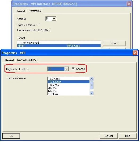
For effective communication, set the PLC device in STEP 7 as shown below. In Properties MPI / Network Settings, set the Highest MPI address to the number closest to the actual device station number.
NOTE:
- HMI sta. no. cannot be the same as PLC sta. no.
- It is highly recommended that device station numbers start from 0 sequentially and that Max. station no. (MPI network) is correctly set.
- Available for EBPro (EasyBuilder) V4.50 and later.
How to Import Tag
SIEMENS STEP 7 allows building files of user-defined tags (*.dif file and *.AWL file), which can then be imported in EBPro (EasyBuilder8000/EasyBuilderPro) via System Parameter Settings. The following describes how to build and import these two types of files.
Building a *.dif File
Open Symbols in SIMATIC Manager
In the SIMATIC Manager, navigate to your project and open Symbols to create user-defined tags.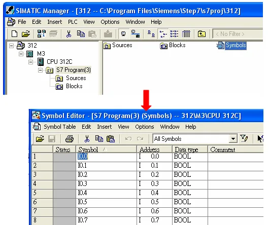
Export the Symbols as a .dif File
In the Symbol Table, click Symbol Table u0026gt; Export to open the Export dialog. Enter a filename (e.g.PLC_Tag.dif), set Save as type to *Data Interchange Format (.DIF), then click Save**.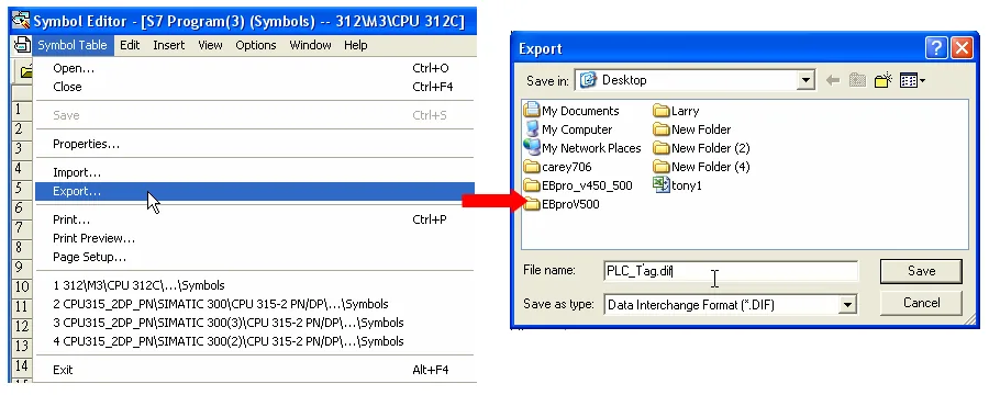
Building a *.AWL File
Open Blocks in SIMATIC Manager
In the SIMATIC Manager, navigate to Blocks and verify the Data Blocks (DB) you want to export are present in the list.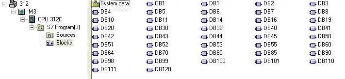
Open LAD/STL/FBD and Generate Source
Open LAD, STL, FBD – Programming S7 Blocks, then click File u0026gt; Generate Source.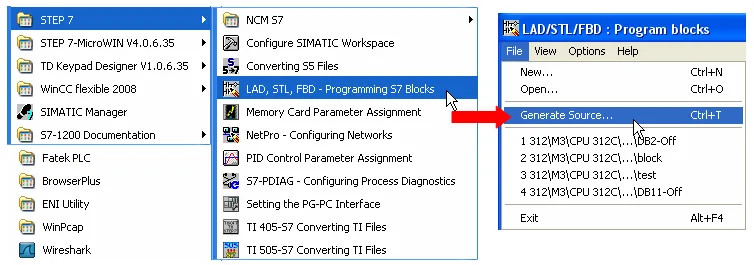
Select Sources as Storage Path and Specify Filename
In the New dialog, select Sources as the storage path, enter an object name (e.g.Object_Tag), then click OK.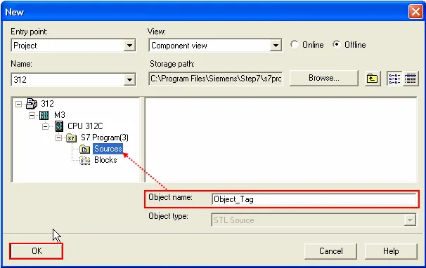
Select the Blocks to Export
In the Generate Source dialog, select the Data Blocks to include in the export (move them to the Blocks Selected list), then click OK.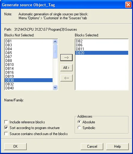
Export Source to Build the *.AWL File
Under Sources in SIMATIC Manager, right-click the saved source file and select Export Source. In the Export source dialog, confirm the filename and click Save.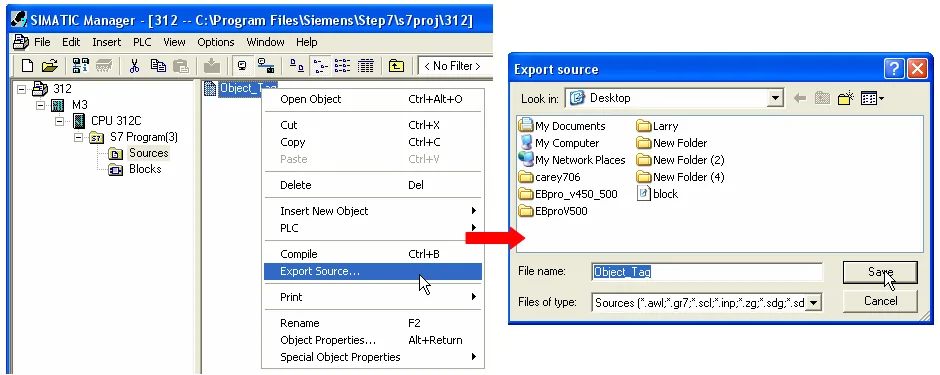
Importing Tags in EasyBuilder
The generated *.dif and *.AWL files can be imported in EasyBuilder8000/EasyBuilderPro via System Parameter Settings by clicking Import Tag.
After selecting both files and clicking OK, tag information is imported successfully.
Wiring Diagram
NOTE: The serial port pin assignments may vary between HMI models.
RS-485 2W
| HMI | Direction | PLC |
|---|---|---|
| Pin assignments | RS485 2W 9P D-Sub Male | |
| Data− | ↔ (bidirectional) | 8 Data− |
| Data+ | ↔ (bidirectional) | 3 Data+ |
| GND | ↔ (bidirectional) | 5 GND |