
Introduction
All Maple Systems HMIs programmed with EBPro (EasyBuilder Pro), including every cMT X Series and cMT Series model, are compatible with SAIA PCD S-BUS Mode. Configure your Controller and HMI/cMT with the following parameters to establish reliable communication.
Supported Series: SAIA PCD series S-Bus mode
HMI Setting
| Parameters | Recommended | Options | Notes |
|---|---|---|---|
| PLC type | SAIA PCD S-BUS Mode | PDS driver | |
| PLC I/F | RS232 | RS232, RS485 | |
| Baud rate | 9600 | 9600, 19200, 38400 | |
| Data bits | 8 | 7, 8 | |
| Parity | None | Even, Odd, None | |
| Stop bits | 1 | 1 | |
| PLC sta. | 0 | 0-255 |
PLC Setting
| Communication mode | 9600,N,8,1 (default) |
|---|---|
| RS232 | Port 0-Type: RS232 |
| RS485 2W | S-BUS Mode: Data(S2), Port 1-Type: RS485 |
PLC Configuration Steps
Open Saia Project Manager
Open Saia Project Manager SP2.0.150 and create a new project.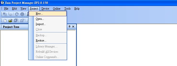
Enter Project Name
Give a project name in the New Project dialog.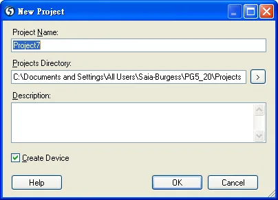
Create New Project
The new project is created and appears in the Project Tree.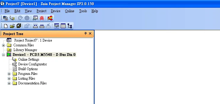
Open Online Settings
Right-click Online Settings in the Project Tree and select Open.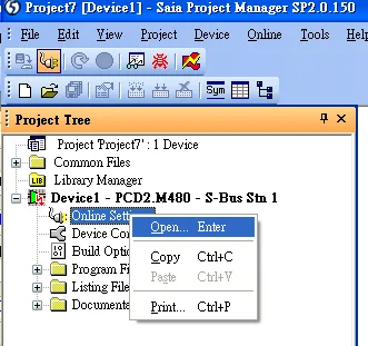
Select PGU Channel
In the Online Settings dialog, select PGU from the channel list.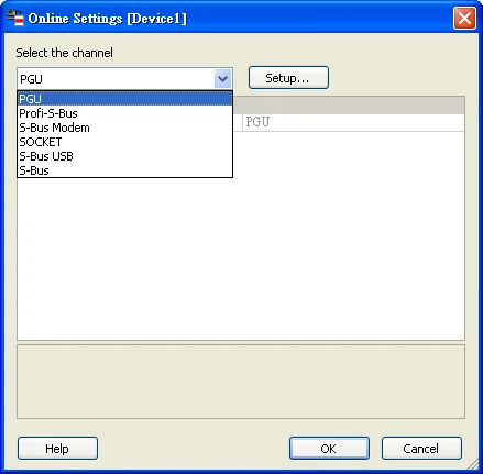
Open Device Configurator
Right-click Device Configurator in the Project Tree and select Open.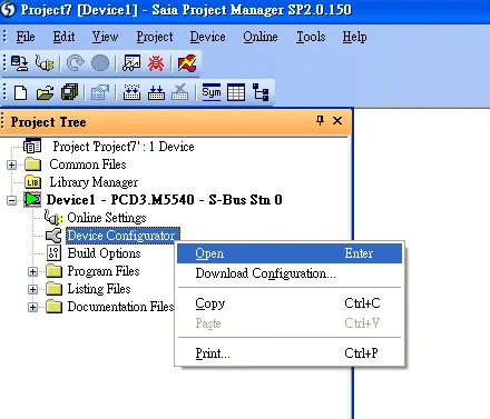
Change Device Type
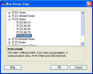
In the Saia Device Configurator, click Change Device Type to select your PLC model.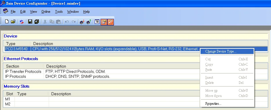
Open Onboard Communications Properties
Select RS232 (PGU) in Type, then right-click Onboard Communications and select Properties.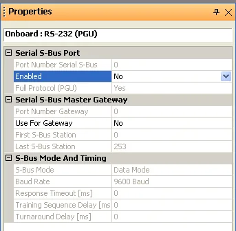
Enable Series S-Bus Port
Select Yes in Series S-Bus Port: Enabled.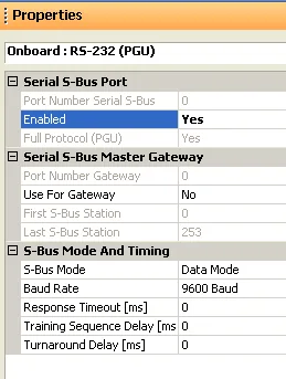
Set Parameters and Upload
Set parameters in S-Bus Mode and Timing, then click the Upload Configuration button to upload to the PLC.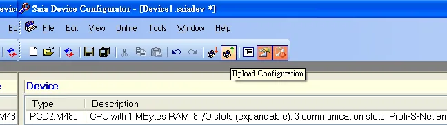
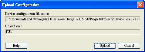
Select S-Bus in Online Settings
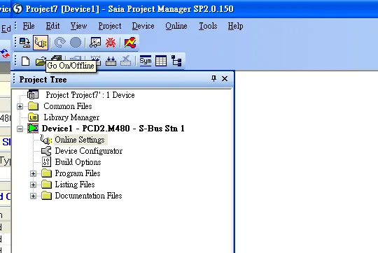
Go to Online Settings u0026gt; Open and select S-Bus to finish the PLC settings.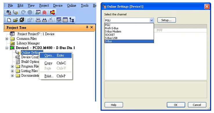
Device Address
| Bit/Word | Device type | Format | Range | Memo |
|---|---|---|---|---|
| B | Flag | DDDDD | 0 ~ 14335 | |
| B | Output | DDDD | 0 ~ 8091 | |
| B | Input | DDDD | 0 ~ 8091 | |
| B | Reg_Bit | DDDDdd | 0 ~ 16383 | dd: Bit no. (00~31) |
| B | DBn_Bit | DDDDDDDDDdd | 0 ~ 536016383 | |
| DW | Register | DDDDD | 0 ~ 16383 | |
| DW | Counter | DDDD | 0 ~ 1599 | |
| DW | Timer | DDDD | 0 ~ 1599 | |
| DW | Reg_Float | DDDDD | 0 ~ 16383 | Support single float point |
| DW | DBn | DDDDDDDDD | 0 ~ 536016383 | |
| DW | DB_String | DDDDDDDDD | 0 ~ 536016383 | |
| DW | R_String | DDDDD | 0 ~ 16383 | |
| DW | DB_Float | DDDDDDDDD | 0 ~ 536016383 | |
| DW | Text | DDDDDDD | 0 ~ 1638300 |
Wiring Diagrams
NOTE: The serial port pin assignments may vary between HMI models.
Diagram 1: RS-232 (SAIA PCD PGU Port RS232 9P D-Sub)
| HMI | Direction | PLC |
|---|---|---|
| Pin assignments | RS232 9P D-Sub Male | |
| Rx | ↔ (bidirectional) | 3 |
| Tx | ↔ (bidirectional) | 2 |
| GND | ↔ (bidirectional) | 5 |
| ↕︎ (tie) | 7 8 |
Diagram 2: RS-485 2W (SAIA PCD1 Port #1 (Port #0) Terminal)
| HMI | Direction | PLC |
|---|---|---|
| Pin assignments | SAIA PCD1 Port #1 (Port #0) Terminal | |
| Data- | ↔ (bidirectional) | 11(29) |
| Data+ | ↔ (bidirectional) | 12(28) |
| GND | ↔ (bidirectional) | GND |