
Introduction
All Maple Systems HMIs programmed with EBPro (EasyBuilder Pro), including every cMT X Series and cMT Series model, are compatible with a Koyo (Automation Direct) K-Sequence PL:C. Configure your Controller and HMI/cMT with the following parameters to establish reliable communication.
Supported Series: KOYO DirectLogic series PLC DL05, DL06, DL105, DL205, DL305, and DL405 series
HMI Settings
| Parameters | Recommended | Options | Notes |
|---|---|---|---|
| PLC type | KOYO DIRECT (K-Sequence) | ||
| PLC I/F | RS232 | RS232, RS485 | |
| Baud rate | 9600 | 9600, 19200, 38400 | |
| Data bits | 8 | 7, 8 | |
| Parity | Odd | Even, Odd, None | |
| Stop bits | 1 | 1 | |
| PLC sta. no. | 1 | 1–90 |
NOTE: Supports communications between HMI and PLC in pass-through mode.
NOTE: Set LW-9903 to 2 to enhance the speed of download/upload PLC program in pass-through mode.
NOTE: When using pass-through, the driver will stop communication between HMI and PLC.
PLC Settings
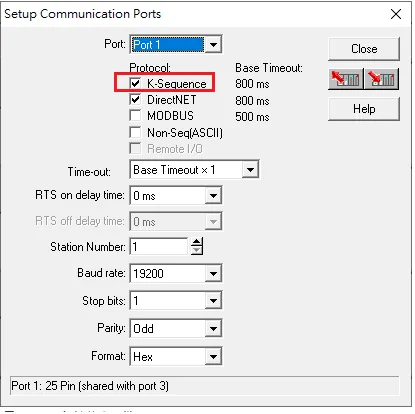
- The PLC must not have a password.
- PLC must be set for Full Duplex operation.
- PLC must be set for No Hardware Handshaking.
- The PLC must be set to use the
KSequence Protocol. - Set the mode switch to the TERM mode.
- When using the D4-440 CPU, the station number must be set to 1.
Device Address
| Bit/Word | Device Type | Format | Range | Memo |
|---|---|---|---|---|
| B | X | OOOO | 0 ~ 4000 | Input Bits |
| B | Y | OOOO | 0 ~ 4000 | Output Bits |
| B | C | OOOOO | 0 ~ 10000 | Control Relays |
| B | T | OOOO | 0 ~ 1000 | Timer Status Bits |
| B | CT | OOOO | 0 ~ 1000 | Counter Status Bits |
| B | S | OOOO | 0 ~ 2000 | |
| B | SP | OOOO | 0 ~ 2000 | |
| B | GX | OOOOO | 0 ~ 10000 | |
| B | GY | OOOOO | 0 ~ 10000 | |
| W | V | OOOOO | 0 ~ 77777 | V Memory |
| W | Timer | OOOO | 0 ~ 1000 | |
| W | Counter | OOOO | 0 ~ 1000 |
Wiring Diagrams
NOTE: The serial port pin assignments may vary between HMI models.
Diagram 1: RS-232 (DL05/DL06/DL105/DL230/DL240/DL250/DL350/DL450 RS232 Port)
| HMI | Direction | PLC |
|---|---|---|
| Pin assignments | RS232 6P RJ12 Male | |
| Rx | ↔ (bidirectional) | 4 |
| Tx | ↔ (bidirectional) | 3 |
| GND | ↔ (bidirectional) | 1 |
Diagram 2: RS-232 (DL06/DL250 CPU Port 2 RS232)
| HMI | Direction | PLC |
|---|---|---|
| Pin assignments | RS232 Port2 15P D-Sub Male | |
| Rx | ↔ (bidirectional) | 2 |
| Tx | ↔ (bidirectional) | 3 |
| GND | ↔ (bidirectional) | 7 |
| ↕︎ (tie) | 4 5 |
Diagram 3: RS-485 4W (DL06/DL250 CPU Port 2 RS422)
NOTE: DL06/DL250 CPU Port 2 includes RS232 and RS422.
| HMI | Direction | PLC |
|---|---|---|
| Pin assignments | RS422 Port2 15P D-Sub Male | |
| Rx- | ↔ (bidirectional) | 10 |
| RX+ | ↔ (bidirectional) | 9 |
| Tx- | ↔ (bidirectional) | 6 |
| Tx+ | ↔ (bidirectional) | 13 |
| GND | ↔ (bidirectional) | 7 |
| ↕︎ (tie) | 11 14 | |
| ↕︎ (tie) | 12 15 |
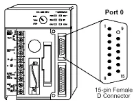
Diagram 4: RS-232 (DL430/DL440/DL450 CPU Unit Port 0 RS232)
The following is the view from the soldering point of a connector.
| HMI | Direction | PLC |
|---|---|---|
| Pin assignments | RS232 Port0 15P D-Sub Male | |
| Rx | ↔ (bidirectional) | 2 |
| Tx | ↔ (bidirectional) | 3 |
| GND | ↔ (bidirectional) | 13 |
| ↕︎ (tie) | 1 7 2 | |
| ↕︎ (tie) | 4 14 |
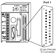
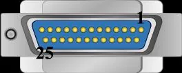
Diagram 5: RS-232 (DL430/DL440/DL450 CPU Unit Port 1 & DL350 CPU Unit Port 2 RS232)
The following is the view from the soldering point of a connector.
| HMI | Direction | PLC |
|---|---|---|
| Pin assignments | RS232 Port1 25P D-Sub Male | |
| Rx | ↔ (bidirectional) | 2 |
| Tx | ↔ (bidirectional) | 3 |
| GND | ↔ (bidirectional) | 7 |
| ↕︎ (tie) | 4 5 |
Diagram 6: RS-485 4W (DL430/DL440/DL450 CPU Unit Port 1 & DL350 CPU Unit Port 2 RS422)
| HMI | Direction | PLC |
|---|---|---|
| Pin assignments | RS422 Port 25P D-Sub Male | |
| Rx- | ↔ (bidirectional) | 16 |
| RX+ | ↔ (bidirectional) | 14 |
| Tx- | ↔ (bidirectional) | 10 |
| Tx+ | ↔ (bidirectional) | 9 |
| GND | ↔ (bidirectional) | 7 |
| ↕︎ (tie) | 19 11 | |
| ↕︎ (tie) | 18 23 |
Diagram 7: RS-485 4W (DL450 CPU Unit Port 3 RS422)
| HMI | Direction | PLC |
|---|---|---|
| Pin assignments | RS422 Port3 25P D-Sub Male | |
| Rx- | ↔ (bidirectional) | 13 |
| RX+ | ↔ (bidirectional) | 15 |
| Tx- | ↔ (bidirectional) | 25 |
| Tx+ | ↔ (bidirectional) | 24 |
| GND | ↔ (bidirectional) | 7 |
Diagram 8: RS-232 (DL205 Series D2-DCM and DL405 Series D4-DCM RS232)
| HMI | Direction | PLC |
|---|---|---|
| Pin assignments | RS232 Port 25P D-Sub Male | |
| Rx | ↔ (bidirectional) | 2 |
| Tx | ↔ (bidirectional) | 3 |
| GND | ↔ (bidirectional) | 7 |
| ↕︎ (tie) | 4 5 |