Introduction
All Maple Systems HMIs programmed with EBPro (EasyBuilder Pro), including every cMT X Series and cMT Series model, are compatible with CANbus CANopen Slave. Configure your Controller and HMI/cMT with the following parameters to establish reliable communication.
Supported series: CAN Bus 2.0a / CAN Bus 2.0B device
HMI Setting
| Parameters | Recommended | Options | Notes |
|---|---|---|---|
| PLC type | CAN Bus CANopen Slave | ||
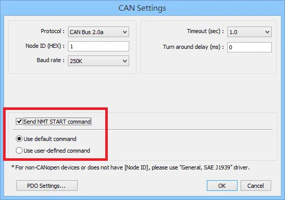
| Node ID (Hex) | 1 | 1 ~ 7F | |
| Baud rate | 250K | 20K~1M | |
| RPDO command with 8 byte | |||
| Send NMT START Command | Use default command / Use user-defined command | ||
| Online simulator | NO | ||
| Extend address mode | NO |
EDS File Import
Follow the steps to import an EDS file.
Open Object Dictionary Settings
Object Dictionary Settings → Setting
Import EDS file.
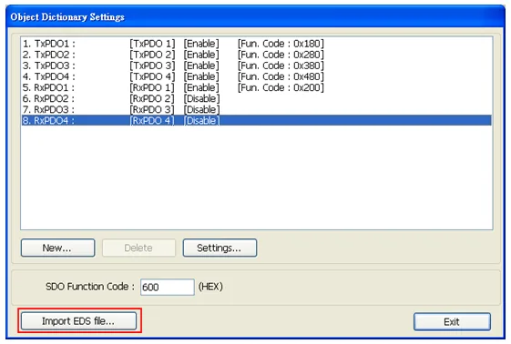
Select EDS File to Import
Select the EDS file to be imported.Confirm Successful EDS Import
Successfully import EDS file.
Device Address
| Bit/Word | Device Type | Format | Range | Memo |
|---|---|---|---|---|
| B | TxPDOn_BIT | Dd | 0 ~ 77 | D: address (unit: byte), d: bit no. |
| B | RxPDOn_BIT | Dd | 0 ~ 77 | D: address (unit: byte), d: bit no. |
| B | SDO_8bit_Bit | HHHHHHo | 0 ~ FFFFFF7 | HHHH(Index)+HH(Sub-index)+o(Bit no) |
| B | SDO_16bit_Bit | HHHHHHdd | 0 ~ HHHHHH15 | HHHH(Index)+HH(Sub-index)+dd(Bit no) |
| B | NMT START Command | Dd | 0 | *Note |
| W | TxPDOn | D | 0 ~ 7 | |
| W | TxPDOn_Byte | D | 0 ~ 7 | |
| W | RxPDOn | D | 0 ~ 7 | |
| W | RxPDOn_Byte | D | 0 ~ 7 | |
| W | SDO_8bit | HHHHHH | 0~FFFFFF | HHHH(Index)+HH(Sub-index) |
| W | SDO_16bit | HHHHHH | 0~FFFFFF | |
| W | SDO_32bit | HHHHHH | 0~FFFFFF |
CAN Settings
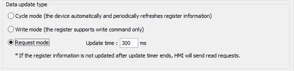
NOTE: NMT START COMMAND will be sent when this BIT is set to ON, and will return to OFF after sending. The [Send NMT START command] in CAN Settings must be checked, otherwise it is invalid. When using NMT START command and Request mode, the [Update time] must be set to 300ms or more.
Wiring Diagram
NOTE: The serial port pin assignments may vary between HMI models.
CANBus
| HMI | Direction | PLC |
|---|---|---|
| Pin assignments | CAN Bus Device | |
| CAN- | ↔ (bidirectional) | CAN- |
| CAN+ | ↔ (bidirectional) | CAN+ |
| GND | ↔ (bidirectional) | GND |
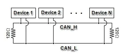
To minimize signal reflection on the CAN bus network, termination resistors should be installed at both ends of the network, as shown in the following figure.