Introduction
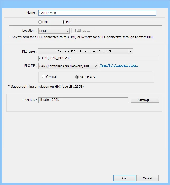
All Maple Systems HMIs programmed with EBPro (EasyBuilder Pro), including every cMT X Series and cMT Series model, are compatible with CANbus 2.0A/2.0B General and SAE J1939. Configure your Controller and HMI/cMT with the following parameters to establish reliable communication.
Supported series: CAN Bus 2.0A / CAN Bus 2.0B / SAE J1939
HMI Settings
| Parameters | Recommended | Options | Notes |
|---|---|---|---|
| PLC type | CAN Bus 2.0A/2.0B General and SAE J1939 | General / SAE J1939 | |
| Baud rate | 250K | 20K~1M | |
| Reset RDO when communication fails | |||
| Online simulator | NO | ||
| Extend address mode | NO |
How to Import SAE J1939 Address Tags
Add CANBus driver
In EBPro (EasyBuilder Pro) add the CAN Bus 2.0A/2.0B General and SAE J1939 driver.Open Address Tag Library
Open Address Tag Library, select User-defined tags and then click New.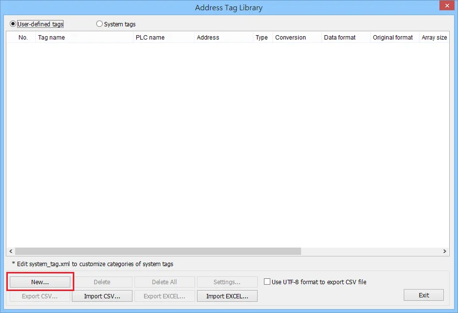
Configure tag name and PLC
Set the following fields:nn- Name: Enter the tag name.n- PLC: Select the SAE J1939 device.n- Address type: Select Bit or Word.nnFor Transmission rate: if Use the default is selected, the HMI will wait for the reply from the CAN device. If Request mode is selected, the HMI will send a polling packet.nnAfter entering the above information, click Settings.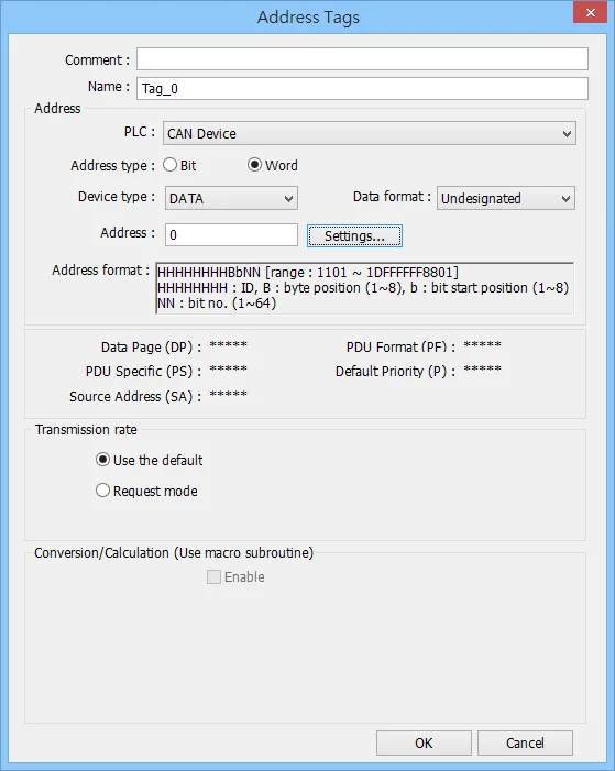
Set CAN device parameters
Set the following parameters according to the specification of the CAN device used.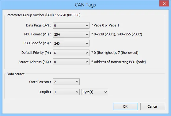
Exit and review tags
After building the tags, click Exit.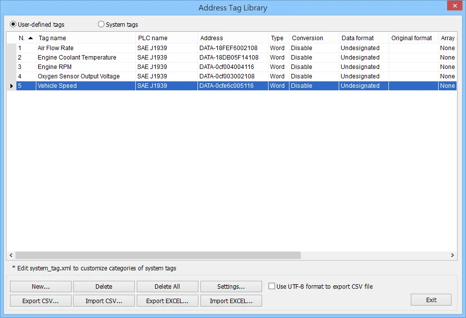
Device Address
| Bit/Word | Device type | Format | Memo |
|---|---|---|---|
| B | DATA_Bit | HHHHHHHHBb | H: ID B: Byte position (1~8) b: Bit start position (1~8) |
| W | DATA | HHHHHHHHBbNN | H: ID B: Byte position (1~8) b: Bit start position (1~8) NN: Bit no. (1~64) |
Wiring Diagram
NOTE: The serial port pin assignments may vary between HMI models.
| HMI | Direction | PLC |
|---|---|---|
| Pin assignments | CAN Bus Device | |
| CAN- | ↔ (bidirectional) | CAN- |
| CAN+ | ↔ (bidirectional) | CAN+ |
| GND | ↔ (bidirectional) | GND |
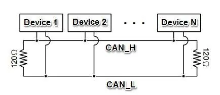
To minimize signal reflection on the CAN bus network, termination resistors should be installed at both ends of the network, as shown in the following figure.