Introduction
All Maple Systems HMIs programmed with EBPro (EasyBuilder Pro) — including every cMT X Series and cMT Series model — are compatible with ABB AC500. Configure your Controller and HMI/CMT with the following parameters to establish reliable communication.
Supported Series: ABB AC500
HMI Settings
| Parameters | Recommended | Options | Notes |
|---|---|---|---|
| PLC type | ABB AC500 | ||
| PLC I/F | RS485 2W | RS232/RS485 2W / Ethernet | |
| Baud rate | 19200 | ||
| Data bits | 8 | ||
| Parity | Even | ||
| Stop bits | 1 | ||
| PLC sta. no. | 0 | ||
| Port no. | 502 | Ethernet | |
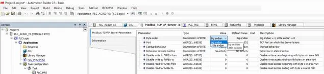
| Byte order | Big endian (V2) | Big endian (V2) Little endian (V2) Big endian (V3) Little endian (V3) | *Note |
NOTE: See AC500 V2 Settings and AC500 V3 Settings below for Automation Builder configuration.
AC500 V2 Settings

AC500 V3 Settings
PLC Settings
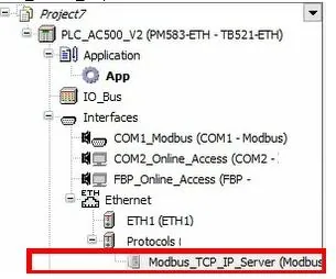
In the PLC IDE, add a Modbus TCP server to your device tree within your Automation Builder software.
Example: PLC_AC500_V2
Device Address
| Bit/Word | Device type | Format | Range | Addressing in Automation Builder |
|---|---|---|---|---|
| B | MX0 | DDDDo | 0 ~ 81917 | %MX0.0.0 ~ 0.8191.7 |
| B | MW_BIT | DDDDDdd | 0 ~ 3276715 | *Note |
| W | MW0 | DDDDD | 0 ~ 32767 | %MW0.0 ~ 0.32767 |
| W | MW1 | DDDDD | 0 ~ 32767 | %MW1.0 ~ 1.32767 |
| DW | MD0 | DDDDD | 0 ~ 16383 | %MD0.0 ~ 0.16383 |
| DW | MD1 | DDDDD | 0 ~ 16383 | %MD1.0 ~ 1.16383 |
NOTE: MW_BIT is used for Bit access in any MW0.
Wiring Diagram
NOTE: The serial port pin assignments may vary between HMI models.
Diagram 1: RS-232
| HMI | Direction | PLC |
|---|---|---|
| Pin assignments | RS232 9P D-Sub Female | |
| Rx | ↔ (bidirectional) | 2 TXD |
| Tx | ↔ (bidirectional) | 3 RXD |
| GND | ↔ (bidirectional) | 5 GND |
Diagram 2: RS-485 2W
| HMI | Direction | PLC |
|---|---|---|
| Pin assignments | RS485 2W 9P D-Sub Female | |
| Data− | ↔ (bidirectional) | 8 Data− |
| Data+ | ↔ (bidirectional) | 3 Data+ |
| GND | ↔ (bidirectional) | 5 GND |
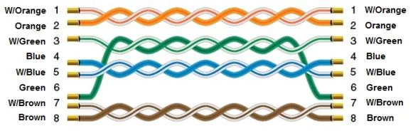
Diagram 3: Ethernet Cable