
Introduction
All Maple Systems HMIs programmed with EBPro (EasyBuilder Pro), including every cMT X Series and cMT Series model, are compatible with Siemens S7-300 MPI. Configure your Controller and HMI/cMT with the following parameters to establish reliable communication.
Supported Series: Siemens S7-300 series PLC
Website: http://www.siemens.com/entry/cc/en/
HMI Settings
| Parameters | Recommended | Options | Notes |
|---|---|---|---|
| PLC type | SIEMENS S7-300 MPI | ||
| PLC I/F | RS-485 2W | ||
| Baud rate | 187.5K | 19200, 187.5K | *Note |
| Data bits | 8 | ||
| Parity | Even | ||
| Stop bits | 1 | ||
| PLC sta. no. | 2 | 2 ~ 31 | |
| Online simulator | NO | ||
| Extend address mode | Yes | ||
| Broadcast command | NO |
NOTE: MPI 19200bps does not support the following models: MT8071iP2, MT8102iP, MT6102iQ, TK6071iP, TK6071iQ, TK8071iP, TK8072iP
Device Address
| Bit/Word | Device Type | Format | Range | Memo |
|---|---|---|---|---|
| B | I | DDDDo | 0 ~ 40957 | Input (I) |
| B | Q | DDDDo | 0 ~ 40957 | Output (O) |
| B | M | DDDDo | 0 ~ 40957 | Bit Memory |
| B | DBnBit | FFFFFDDDDo | 0 ~ 6553599997 | Data Register Bit |
| B | DBxBit | FFFFFDDDDDo | 0 ~ 10700655327 | |
| B | DB1Bit ~ DB99Bit | DDDDDo | 0 ~ 655357 | Data Register Bit |
| W | IW | DDDD | 0 ~ 4095 | Input (I) |
| W | QW | DDDD | 0 ~ 4095 | Output (O) |
| Byte | MB | DDDD | 0 ~ 4095 | Bit Memory Byte |
| W | MW | DDDD | 0 ~ 4095 | Bit Memory |
| DW | MD | DDDD | 0 ~ 4094 | |
| Byte | DBBn | FFFFFDDDD | 0 ~ 655359999 | Data Register |
| Byte | DBBx | FFFFFDDDDD | 0 ~ 1070065535 | |
| W | DBn | FFFFFDDDD | 0 ~ 655359999 | Data Register (must be even) |
| W | DBx | FFFFFDDDDD | 0 ~ 1070065535 | |
| DW | DBDn | FFFFFDDDD | 0 ~ 655359999 | Data Register Double Word (must be even) |
| DW | DBDx | FFFFFDDDDD | 0 ~ 1070065535 | |
| W | DBn_String | FFFFFDDDD | 0 ~ 655359999 | |
| W | DBx_String | FFFFFDDDDD | 0 ~ 1070065535 | |
| W | DBn_String1 | FFFFFDDDD | 0 ~ 655359999 | |
| W | DBx_String1 | FFFFFDDDDD | 0 ~ 1070065535 | |
| DW | DBDn_String | FFFFFDDDD | 0 ~ 655359999 | |
| DW | DBDx_String | FFFFFDDDDD | 0 ~ 1070065535 | |
| W | DB1 ~ DB99 | DDDDD | 0 ~ 65535 | Data Register (must be even) |
| W | T | DDDDD | 0 ~ 65535 | |
| W | C | DDDDD | 0 ~ 65535 |
Double word and floating point value must use DBDn device type.
Multi-HMIs-Multi-PLCs Communication Setting
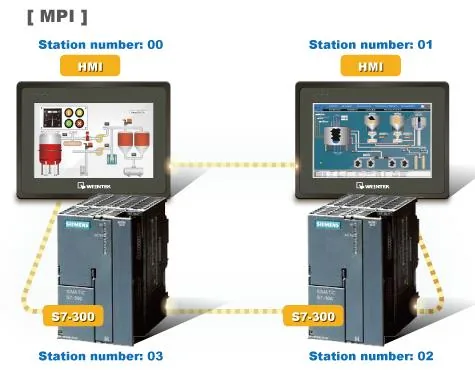
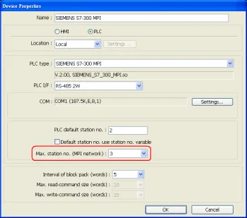
For SIEMENS S7-300 MPI driver in Multi-HMIs-Multi-PLCs communication, the Max. station no. (MPI network) parameter must be correctly set. This setting is relevant to the station number of the devices. As shown below, two HMIs (station no. 0, 1) and two PLCs (station no. 2, 3) are in an MPI network — Max. Station No. should be set to 3.
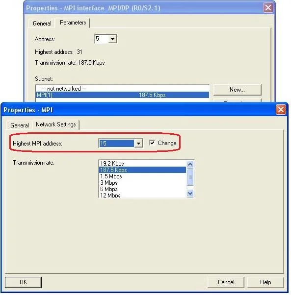
For the effectiveness of communication, users may set the PLC device in STEP 7 as shown below. In Properties MPI / Network Settings, set Highest MPI address to the number closest to the actual device station number.
- HMI sta. no. cannot be the same as PLC sta. no.
- It is highly recommended that the device station numbers start from 0 sequentially and that Max. station no. (MPI network) is correctly set.
How to Import Tag
SIEMENS STEP 7 allows building files of user-defined tags (*.dif file and *.AWL file), and importing these files in EasyBuilder8000/EasyBuilderPro → System Parameter Settings. The following describes how to build and import these two types of files.
Building a *.dif File
Open Symbols in SIMATIC Manager
In Symbols, create user-defined tags.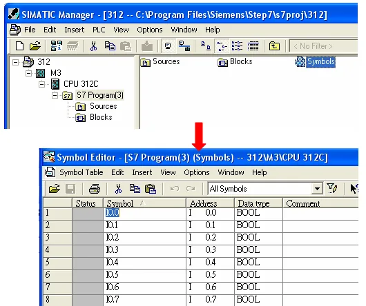
Export the Symbols File
Click Export to export the edited file and click Save. Save the file as type *Data Interchange Format (.DIF)**.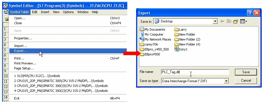
Building a *.AWL File
Create Blocks in SIMATIC Manager
In Blocks, create items as shown below.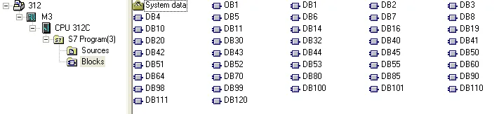
Open LAD/STL/FBD and Generate Source
Open LAD/STL, FBD – Programming S7 Blocks, then click File → Generate Source.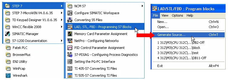
Specify the Source Storage Path
Select Sources as the storage path, specify the file name, then click OK.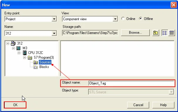
Select Blocks to Export
Select the objects to be exported, then click OK.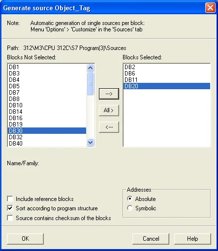
Export the Source as an AWL File
Under Sources, select the saved file, then right-click and choose Export Source to build the*.AWLfile.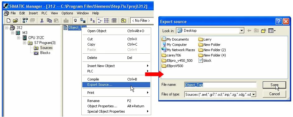
Importing Tags into EBPro (EasyBuilder)
Open Import Address Tag Dialog
In System Parameter Settings → Device, select the SIEMENS S7-300 MPI device and click Import Tag. Browse to select the.diffile and the.AWLfile, then click OK.Confirm Successful Import
Tag information will be confirmed as successfully imported.
Pass-Through Settings
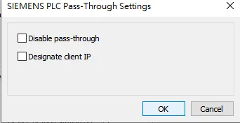
[Designate client IP]: In Pass-through mode, designate the client IP address to connect to the HMI. The “client” usually refers to the Siemens Step 7 application.
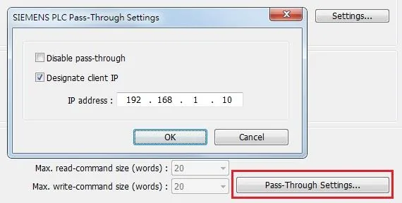
[Utility Manager Settings]: Utility Manager → Serial Pass-through
- Mode: MPI ISOTCP
NOTE: Only supports single-step monitoring address; continuous monitoring address function cannot be used in pass-through.
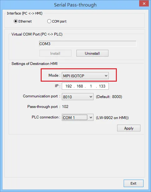
The following lists the system registers relevant to Siemens S7-200 PPI and Siemens S7-300 MPI Pass-through feature.
LW-10850: disable/enable (0: disable, 1: normal, 2: IP limited) — Siemens pass-throughLW-10851: destination COM port (Siemens pass-through) — generally refers to the COM port connected with the PLCLW-10852: destination PLC station no. (Siemens pass-through)LW-10853: communication protocol (0: invalid, 1: PPI, 2: MPI) — Siemens pass-throughLW-10854toLW-10857: IP of connecting client (Siemens pass-through) — displays current client IP address connected with HMILW-10858toLW-10861: IP of designated client (Siemens pass-through) — if LW-10850 is set to 1, these registers can be used to designate the client IP connected with HMILW-10862: connection status (0: ready, 1: client connecting) — Siemens pass-throughLW-10863: execution status (0: normal, 1: error) — Siemens pass-throughLW-10864: the last error (Siemens pass-through)
The following table lists the error codes, the description of each code, and the possible reason.
| Error Code | Description | Possible Reason |
|---|---|---|
| 0 | Successfully executed | |
| 1 | Prohibit client from connecting HMI | HMI is already running pass-through and won’t accept any request from other client. |
| 2 | Prohibit client from connecting HMI | When LW-10850 is set to 1, the client IP for connecting HMI is different from the IP specified in LW-10858 ~ LW-10861. |
| 3 | Invalid communication protocol | Invalid setting in LW-10853. |
| 4 | Invalid PLC station number | The PLC station number specified in LW-10852 does not exist. |
| 5 | Delayed communication | PLC connection failure. |
| 6 | Busy communication | PLC does not accept pass-through request, please confirm PLC settings. |
| 7 | Invalid pass-through request | Environment setup failure. |
EasyAccess 2.0 Network Pass-Through
Obtain SubnetID Using S7-300 MPI SubnetID Tool
Create S7-300 MPI Project and Download to HMI
Create an S7-300 MPI project. In Pass-Through Settings, leave all options unchecked. Download the project to the HMI and verify it communicates with the PLC.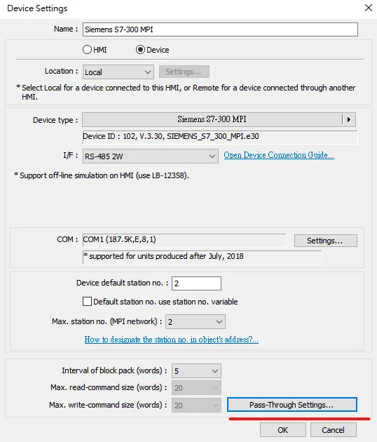
Connect to HMI via EasyAccess 2.0 and Obtain HMI IP
Open EasyAccess 2.0, connect to the target HMI, and obtain the HMI IP address.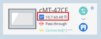
Open the S7-300 MPI SubnetID Tool in Utility Manager
Navigate to Utility Manager → S7-300 MPI SubnetID tool.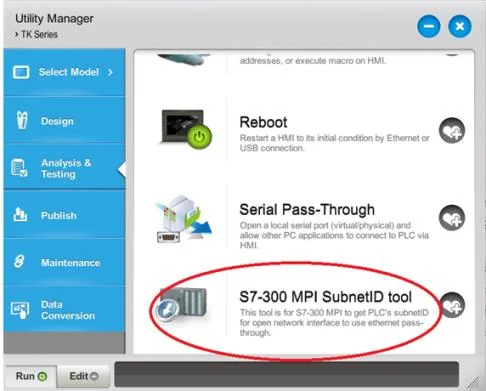
Set HMI IP and Get SubnetID
Set the HMI IP address and Port number, then click the Get SubnetID button.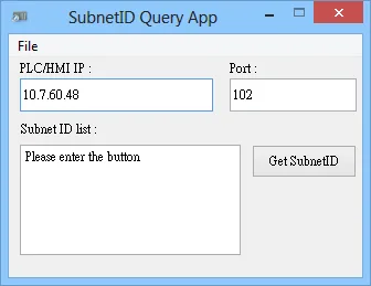
Siemens Step 7 Software Operation
Enable Set PG/PC Interface
In SIMATIC Manager, open Options → Set PG/PC Interface.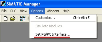
Select Network Interface and Set TCP/IP Properties
In Interface, select the network card used (e.g. TCP/IP → Intel(R) PRO/1000). Click Properties to open the interface properties, and make sure to check Do not assign IP addresses automatically.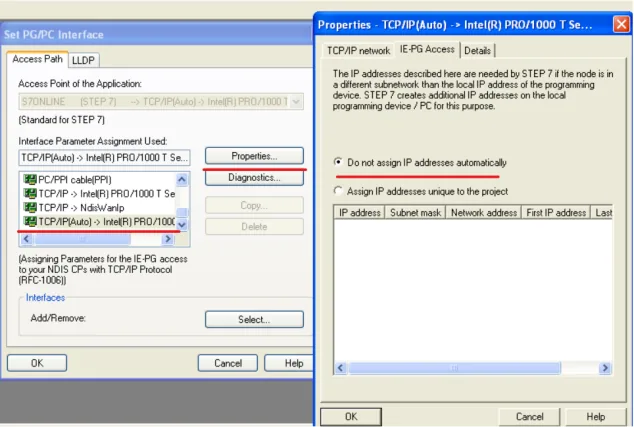
Upload Station to PG
Open the project and click PLC → Upload Station to PG…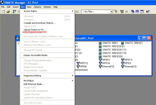
Select Gateway and Fill in Connection Fields
Select Can be reached by means of gateway. Fill in the fields in sequence: MPI, PLC station number, S7 subnet ID, IP address. Then click OK directly to start uploading the PLC project.nnNOTE: If you click View, the PLC will not be found.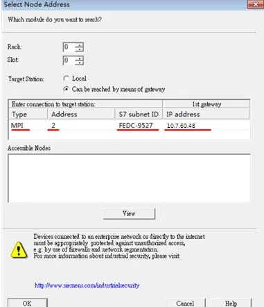
Wiring Diagram
NOTE: The serial port pin assignments may vary between HMI models.
RS-485 2W
| HMI | Direction | PLC |
|---|---|---|
| Pin assignments | RS485 2W 9 D-Sub Male | |
| Data- | ↔ (bidirectional) | 8 Data- |
| Data+ | ↔ (bidirectional) | 3 Data+ |
| GND | ↔ (bidirectional) | 5 GND |