
Introduction
All Maple Systems HMIs programmed with EBPro (EasyBuilder Pro), including every cMT X Series and cMT Series model, are compatible with Mitsubishi Q00/Q00UJ/Q01/QJ71. Configure your Controller and HMI/cMT with the following parameters to establish reliable communication.
Supported Series: Mitsubishi Q series PLC with QJ71C24 communication module, Q00, Q00J, Q00UJ, Q01, Q02H, Q06H, Q12H, Q25H, Q12PH, Q25PH CPU port.
Website: http://www.mitsubishi-automation.com
HMI Settings
| Parameters | Recommended | Options | Notes |
|---|---|---|---|
| PLC type | Mitsubishi Q00/Q00UJ/Q01/QJ71 | ||
| PLC I/F | RS232 | RS485 2W/4W, RS232 | |
| Baud rate | 9600 | 9600~115200 | |
| Data bits | 8 | ||
| Parity | Odd | ||
| Stop bits | 1 | ||
| PLC sta. no. | 0 | ||
| Online simulator | Yes | ||
| Extend address mode | NO |
PLC Settings
Q00, Q01 CPU Port Setting
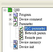
- In GX Developer “PLC data list” click [PLC parameter].
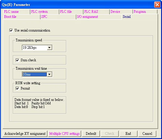
- In “PLC parameter” go to [Serial] page.
- Select [Use serial communication].
- Set [Transmission speed] to 9600~115200.
- Select [Sum check].
- Set [Transmission wait time] to 10ms.
- Permit [RUN write setting].
- Click [End] to close the dialog.
- Write the PLC Parameter to PLC.
- Reset PLC, the parameter will be actived.
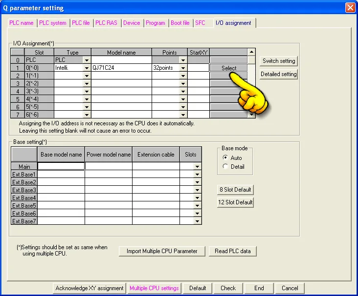
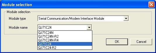
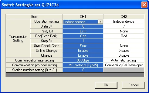
QJ71 Setting
Device Address
| Bit/Word | Device Type | Format | Range | Memo |
|---|---|---|---|---|
| B | X | HHHH | 0 ~ 1fff | Input Relay |
| B | Y | HHHH | 0 ~ 1fff | Output Relay |
| B | M | DDDDD | 0 ~ 61439 | Internal Relay |
| B | L | DDDDD | 0 ~ 32767 | Latch Relay |
| B | F | DDDDD | 0 ~ 32767 | Annunciator |
| B | V | DDDDD | 0 ~ 32767 | Edge Relay |
| B | B | HHHH | 0 ~ efff | Link Relay |
| B | TC | DDDD | 0 ~ 2047 | Timer Coil |
| B | SS | DDDDD | 0 ~ 25471 | Retentive Timer Contact |
| B | SC | DDDDD | 0 ~ 25471 | Retentive Timer Coil |
| B | CS | DDDDD | 0 ~ 25471 | Counter Contact |
| B | CC | DDDDD | 0 ~ 25471 | Counter Coil |
| B | SB | HHH | 0 ~ 7ff | Special Link Relay |
| B | S | DDDD | 0 ~ 8191 | Step Relay |
| B | DX | HHHH | 0 ~ 1fff | Direct Input |
| B | DY | HHHH | 0 ~ 1fff | Direct Output |
| B | TS | DDDD | 0 ~ 2047 | Timer Contact |
| B | SM | DDDD | 0 ~ 2047 | |
| B | D_Bit | DDDDDDDh | 0 ~ 4212735f | |
| B | W_Bit | HHHHh | 0 ~ 2ffff | |
| B | ZR_Bit | HHHHHh | 0 ~ fe7fff | |
| B | ZR_Dec_Bit | DDDDDDDh | 0 ~ 1042431f | |
| W | W | HHHH | 0 ~ 2fff | Link Register |
| W | TN | DDDD | 0 ~ 2047 | Timer Current Value |
| W | SN | DDDD | 0 ~ 2047 | Retentive Timer Current Value |
| W | CN | DDDD | 0 ~ 1023 | Counter Current Value |
| W | R | FFDDDDD | 0 ~ 3132767 | File Register (FF: File No. 0~31) (DDDDD: 0~32767) |
| W | SW | HHH | 0 ~ 7ff | Special Link Register |
| W | Z | DD | 0 ~ 19 | Index Register |
| W | ZR | HHHHH | 0 ~ fe7a5 | File Register |
| W | ZR_decimal_addr | DDDDDDD | 0 ~ 1042341 | |
| W | D | DDDDDDD | 0 ~ 4212735 | Data Register |
| W | SD | DDDD | 0 ~ 2047 | |
| W | Serial_No | D | 0 ~ 7 | |
| W | Product_No | D | 0 ~ 7 |
Wiring Diagrams
NOTE: The serial port pin assignments may vary between HMI models.
Diagram 1: RS-485 4W: QJ71C24 CH.2 RS422 Terminal
| HMI | Direction | PLC |
|---|---|---|
| Pin assignments | QJ71C24 CH.2 RS422 Terminal | |
| Rx- | ↔ (bidirectional) | SDB |
| RX+ | ↔ (bidirectional) | SDA |
| Tx- | ↔ (bidirectional) | RDB |
| Tx+ | ↔ (bidirectional) | RDA |
| GND | ↔ (bidirectional) | GND |
Diagram 2: RS-232: QJ71C24 CH.2 RS232
| HMI | Direction | PLC |
|---|---|---|
| Pin assignments | RS232 9P D-Sub Male | |
| Rx | ↔ (bidirectional) | TXD-3 |
| Tx | ↔ (bidirectional) | RXD-2 |
| GND | ↔ (bidirectional) | GND-5 |
| ↕︎ (tie) | DCD-1 DTR-4 DSR-6 | |
| ↕︎ (tie) | RTS-7 CTS-8 |
Diagram 3: RS-232: 6P Mini-DIN: Q00, Q01 CPU Port
The following is the view from the soldering point of a connector.

| HMI | Direction | PLC |
|---|---|---|
| Pin assignments | RS232 6P Mini-Din Male | |
| Rx | ↔ (bidirectional) | 1 |
| Tx | ↔ (bidirectional) | 2 |
| GND | ↔ (bidirectional) | 4 |
Diagram 4: RS-232: 6P Mini-DIN: Q00UJ CPU Port
The following is the view from the soldering point of a connector.
| HMI | Direction | PLC |
|---|---|---|
| Pin assignments | RS232 6P Mini-DIN Male | |
| Rx | ↔ (bidirectional) | 1 |
| Tx | ↔ (bidirectional) | 2 |
| GND | ↔ (bidirectional) | 4 |
| ↕︎ (tie) | 5 6 |