
Introduction
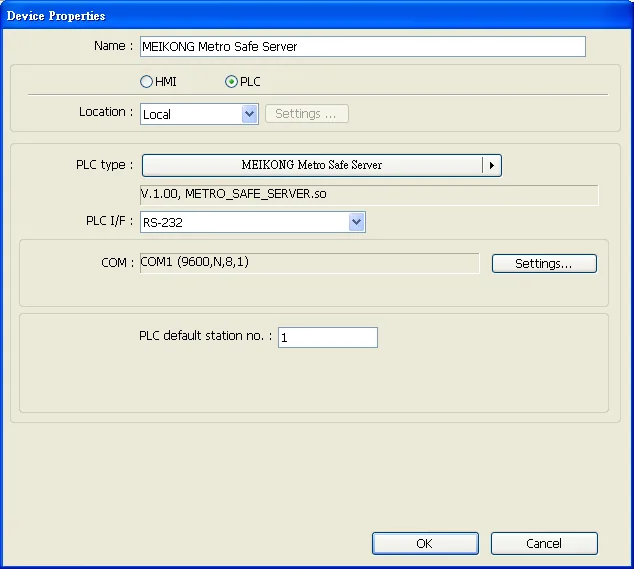
All Maple Systems HMIs programmed with EBPro (EasyBuilder Pro), including every cMT X Series and cMT Series model, are compatible with MEIKONG Metro Safe Server. Configure your Controller and HMI/cMT with the following parameters to establish reliable communication.
Supported Series: MEIKONG Metro Safe Server
HMI Settings
| Parameters | Recommended | Options | Notes |
|---|---|---|---|
| PLC type | MEIKONG Metro Safe Server | ||
| PLC I/F | RS-485 2W | RS232/RS485 | |
| Baud rate | 9600 | 9600~115200 | |
| Data bits | 8 | 7,8 | |
| Parity | None | Even,Odd,None | |
| Stop bits | 1 | 1,2 | |
| PLC sta. no. | 1 | 0~252 |
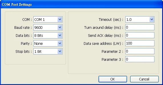
In COM Port Settings, the data read will be stored in 25 consecutive addresses starting from [Data save address (LW)] as shown below. Data will be stored in LW-100 to LW-124.
Protocol
| Byte | Description |
|---|---|
| 0 | AA |
| 1 | E0 |
| 2 | C5 (The first 3 bytes are fixed, which represents the start of the message.) |
| 3 | Address (range 0–252) |
| 4 | Date — Year tens digit |
| 5 | Date — Year unit digit |
| 6 | Date — Month tens digit |
| 7 | Date — Month unit digit |
| 8 | Date — Day tens digit |
| 9 | Date — Day unit digit |
| 10 | Time — Hour tens digit |
| 11 | Time — Hour unit digit |
| 12 | Time — Minute tens digit |
| 13 | Time — Minute unit digit |
| 14 | Time — Second tens digit |
| 15 | Time — Second unit digit |
| 16 | 1-Manual; 2-Automatic |
| 17 | The number of slaves. |
| 18 | The sequence number of slave. |
| 19 | Slave status: 1-Normal; 2-Warning; 3-Emergency; 4-Disconnected |
| 20 | Backup power: 1-Normal; 2-Abnormal voltage; 3-Disconnect; 4-Short |
| 21 | 00 |
| 22 | 00 |
| 23 | EE |
| 24 | BB (The last 4 bytes are fixed, which represents the end of the message.) |
Wiring Diagrams
NOTE: The serial port pin assignments may vary between HMI models.
Diagram 1: RS-232
| HMI | Direction | PLC |
|---|---|---|
| Pin assignments | RS232 9P D-Sub Female | |
| Rx | ↔ (bidirectional) | TXD |
| Tx | ↔ (bidirectional) | RXD |
| GND | ↔ (bidirectional) | GND |
| ↕︎ (tie) | RTS CTS |
Diagram 2: RS-485 4W
| HMI | Direction | PLC |
|---|---|---|
| Pin assignments | RS485 4W 9P D-Sub Male | |
| Rx- | ↔ (bidirectional) | Tx- |
| RX+ | ↔ (bidirectional) | Tx+ |
| Tx- | ↔ (bidirectional) | Rx- |
| Tx+ | ↔ (bidirectional) | Rx+ |
| GND | ↔ (bidirectional) | GND |
Diagram 3: RS-485 2W
| HMI | Direction | PLC |
|---|---|---|
| Pin assignments | RS485 2W 9D-Sub Male | |
| Data- | ↔ (bidirectional) | D- |
| Data+ | ↔ (bidirectional) | D+ |
| GND | ↔ (bidirectional) | GND |