
Introduction
All Maple Systems HMIs programmed with EBPro (EasyBuilder Pro), including every cMT X Series and cMT Series model, are compatible with a Rockwell/Allen-Bradley DH485. Configure your Controller and HMI/cMT with the following parameters to establish reliable communication.
Supported Series: Rockwell/Allen-Bradley MicroLogix 1000, 1100, 1200, 1400, 1500, SLC 5/01, 5/02, 5/03, 5/04, 5/05.
Website: https://www.rockwellautomation.com/
HMI Setting
| Parameters | Recommended | Options | Notes |
|---|---|---|---|
| PLC type | Rockwell DH485 | ||
| PLC I/F | RS485 2W | RS232 | |
| Baud rate | 19200 | 9600, 19200 | |
| Data bits | 8 | ||
| Parity | Even | ||
| Stop bits | 1 | ||
| HMI sta. no. | 0 | 2 | |
| PLC sta. no. | 1 | 1-31 | |
| Online simulation | YES | ||
| Extend address mode | NO |
PLC Setting
| Communication mode | Notes |
|---|---|
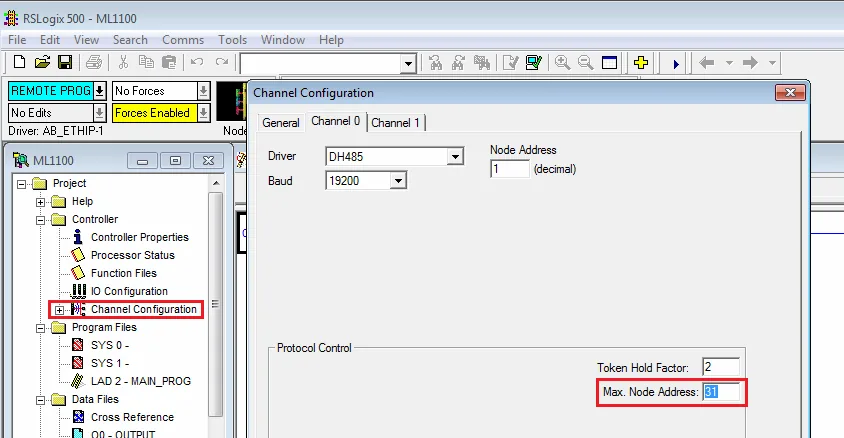
| DH485 protocol 19200 (default) | Set the Max. Node Address to the number of PLCs in use. |
Device Address
| Bit/Word | Device | Format | Range | Memo |
|---|---|---|---|---|
| B | I1 | DDDdd | 0 ~ 25515 | Input (I) |
| B | O0 | DDDdd | 0 ~ 25515 | Output (O) |
| B | I1n_Bit | SSEEdd | 0 ~ 303115 | SS: slot, EE: sub element, dd: bit |
| B | O0n_Bit | SSEEdd | 0 ~ 303115 | SS: slot, EE: sub element, dd: bit |
| B | B3 | DDDdd | 0 ~ 25515 | Bit data file (B3) |
| B | B10 ~ 13 | DDDdd | 0 ~ 25515 | Bit data file (B10 ~ 13) |
| B | Bfn | FFFDDDdd | 0 ~ 25525515 | Bit data file (B3, 10 ~ 254) |
| B | NfnBit | FFFDDDdd | 0 ~ 25525515 | Integer data file bit level (N7, 10 ~ 254) |
| B | S_Bit | DDDdd | 0 ~ 25515 | Status file |
| W | I1n | SSEE | 0 ~ 3031 | SS: slot, EE: sub element |
| W | O0n | SSEE | 0 ~ 3031 | SS: slot, EE: sub element |
| W | T4SV | DDD | 0 ~ 255 | Timer Preset Value (T4) |
| W | T4PV | DDD | 0 ~ 255 | Timer Accumulator Value (T4) |
| W | C5SV | DDD | 0 ~ 255 | Counter Preset Value (C5) |
| W | C5PV | DDD | 0 ~ 255 | Counter Accumulator Value (C5) |
| W | TfnSV | FFFDDD | 0 ~ 255255 | Timer Preset Value |
| W | TfnPV | FFFDDD | 0 ~ 255255 | Timer Accumulator Value |
| W | CfnSV | FFFDDD | 0 ~ 255255 | Counter Preset Value |
| W | CfnPV | FFFDDD | 0 ~ 255255 | Counter Accumulator Value |
| W | F8 | DDD | 0 ~ 255 | Floating point data file (F8) |
| W | N7 | DDD | 0 ~ 255 | Integer data file (N7) |
| W | N10 ~ 15 | DDD | 0 ~ 255 | Integer data file (N10 ~ 15) |
| W | Nfn | FFFDDD | 0 ~ 255255 | Integer data file (N7, 10 ~ 254) |
| W | S | DDD | 0 ~ 255 | Status file |
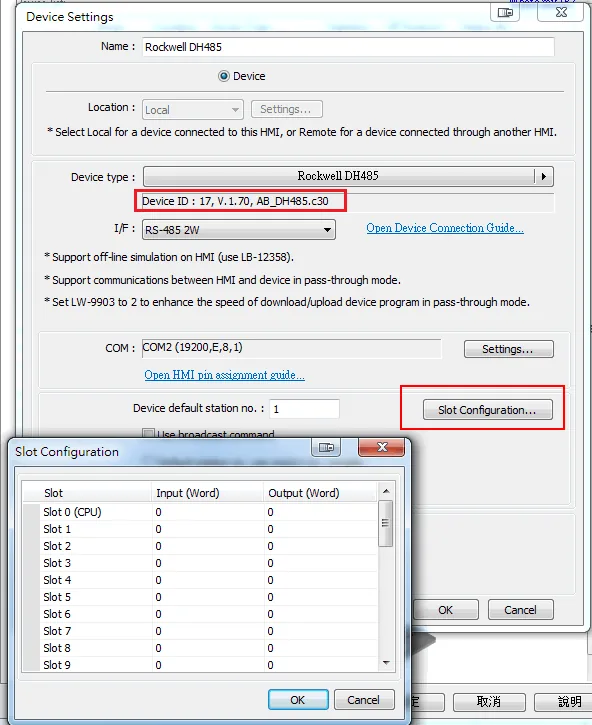
Slot Configuration
NOTE: EBpro V6.07.02 or driver version V1.70 and later do not need to set Slot Configuration. Only older versions need to set this item.
Import Tags
-
Export Tag Database
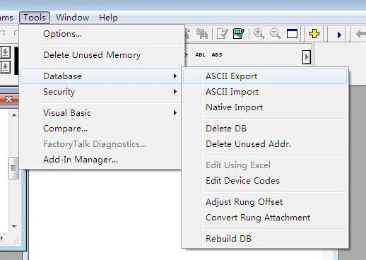
In RSLogix 500, navigate to Tools → Database → ASCII Export.
Configure Export Settings
Select the CSV tab, check Addr/Symbol Desc., and enter the destination file names.Select Export Destination
Browse to the desired destination directory and confirm the selection.Confirm Export Result
The Export Results dialog confirms the address/symbol description database has been exported to CSV format.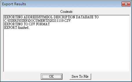
Import Tags in EBPro (EasyBuilderPro)
In EBPro (EasyBuilderPro), go to System Parameter → Device. Create a Rockwell DH485 driver, click Import Tags, and select the CSV file to import.
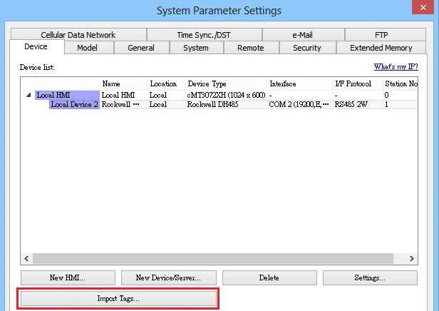
-
Select Tags to Import
Select the tags to import from the list and click OK.
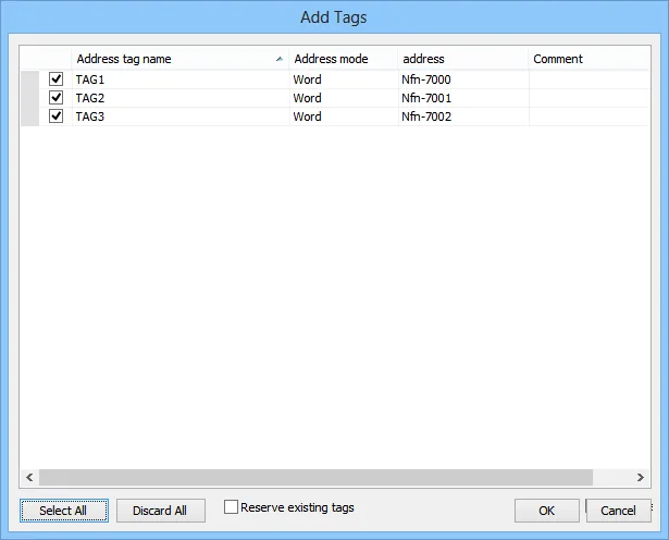
-
Verify Import Success
A confirmation dialog appears: “Imported tag information successfully.”
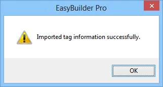
Wiring Diagram
NOTE: The serial port pin assignments may vary between HMI models.
Diagram 1: RS-232 (9P D-Sub to 8P Mini-DIN)
MicroLogix 1000, 1100, 1200, and 1500 must set DH485 protocol. The following is the view from the soldering point of a connector.
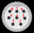
| HMI | Direction | PLC |
|---|---|---|
| Pin assignments | MicroLogix RS232 8P Mini-DIN Male | |
| Rx | ↔ (bidirectional) | 7 TXD |
| Tx | ↔ (bidirectional) | 4 RXD |
| GND | ↔ (bidirectional) | 2 GND |
Diagram 2: RS-232 (9P D-Sub to 9P D-Sub)
SLC5/03, 5/04, 5/05 CH0 must set DH485 protocol.
| HMI | Direction | PLC |
|---|---|---|
| Pin assignments | AB CPU CH0 RS232 9P D-Sub Female | |
| Rx | ↔ (bidirectional) | 3 TD |
| Tx | ↔ (bidirectional) | 2 RD |
| GND | ↔ (bidirectional) | 5 GND |
Diagram 3: RS-485 2W
SLC500 Fixed type, SLC5/01, 5/02, 5/03 CH1. HMI cannot connect to 1747-AIC peripheral port.
| HMI | Direction | PLC |
|---|---|---|
| Pin assignments | AB SLC500 DH485 RJ45 Male | |
| Data- | ↔ (bidirectional) | 2 SDB |
| Data+ | ↔ (bidirectional) | 1 SDA |
| GND | ↔ (bidirectional) | 7 GND |