Introduction
All Maple Systems HMIs programmed with EBPro (EasyBuilder Pro), including every cMT X Series and cMT Series model, are compatible with a Rockwell/Allen-Bradley EtherNet/IP DF1 PLC. Configure your Controller and HMI/cMT with the following parameters to establish reliable communication.
Supported Series: Rockwell MicroLogix 1100, 1400, SLC5/05 Ethernet port. MicroLogix1000, 1200, 1500, SLC 5/03, 5/04 with 1761-NET-ENI.
Website: rockwellautomation.com
HMI Settings
| Parameters | Recommended | Options | Notes |
|---|---|---|---|
| PLC type | Rockwell EtherNet/IP (DF1) | ||
| PLC I/F | Ethernet | ||
| Port no. | 44818 | ||
| HMI sta. no. | 0 | ||
| PLC sta. no. | 1 |
PLC Settings
Communication mode: Port Setting: 10/100 Mbps Full Duplex/Half Duplex
Device Address
| Bit/Word | Device | Format | Range | Memo |
|---|---|---|---|---|
| B | I1 | DDDdd | 0 ~ 255·15 | Input (I) |
| B | O0 | DDDdd | 0 ~ 255·15 | Output (O) |
| B | I1n_Bit | SSEEdd | 0 ~ 30·31·15 | SS: slot, EE: sub element, dd: bit |
| B | O0n_Bit | SSEEdd | 0 ~ 30·31·15 | SS: slot, EE: sub element, dd: bit |
| B | B3 | DDDdd | 0 ~ 255·15 | Bit data file (B3) |
| B | S_Bit | DDDDDDdd | 0 ~ 255·255·15 | Status file |
| B | Lfn_Bit | FFFDDDdd | 0 ~ 255·255·31 | Long (Bit) |
| B | Bfn | FFFDDDdd | 0 ~ 255·255·15 | Bit data file (B3, 10 ~ 254) |
| B | NfnBit | FFFDDDdd | 0 ~ 255·255·15 | Integer data file bit level (N7, 10 ~ 254) |
| W | I1n | SSEE | 0 ~ 30·31 | SS: slot, EE: sub element |
| W | O0n | SSEE | 0 ~ 30·31 | SS: slot, EE: sub element |
| W | T4SV | DDD | 0 ~ 255 | Timer Preset Value (T4) |
| W | T4PV | DDD | 0 ~ 255 | Timer Accumulator Value (T4) |
| W | C5SV | DDD | 0 ~ 255 | Counter Preset Value (C5) |
| W | C5PV | DDD | 0 ~ 255 | Counter Accumulator Value (C5) |
| W | TfnSV | FFFDDD | 0 ~ 255·255 | Timer Preset Value |
| W | TfnPV | FFFDDD | 0 ~ 255·255 | Timer Accumulator Value |
| W | CfnSV | FFFDDD | 0 ~ 255·255 | Counter Preset Value |
| W | CfnPV | FFFDDD | 0 ~ 255·255 | Counter Accumulator Value |
| W | S | DDD | 0 ~ 255 | Status (S) |
| W | N7 | DDD | 0 ~ 255 | Integer data file (N7) |
| W | Nfn | FFFDDD | 0 ~ 255·255 | Integer data file (N7, 10 ~ 254) |
| DW (F) | F8 | DDD | 0 ~ 255 | Floating point data file (F8) |
| DW (F) | Ffn | FFFDDD | 0 ~ 255·255 | Floating point data file (F8, 10 ~ 254) |
| DW | Lfn | FFFDDD | 0 ~ 255·255 | Driver version 2.00 or later supported |
| W | Bfn_Word | FFFDDD | 0 ~ 255·255 | Bit data file (Word) |
| W | STfn | DDD.DDD.DD | 0 ~ 255.255.40 | File no. · Element no. · Data no. |
Wiring Diagram
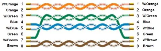
NOTE: Connect the HMI directly to the SLC 500 or SLC5/05 Ethernet port using a crossover cable.
The diagram below shows the Ethernet cable wiring.
Use the following pin-to-pin wiring for an Ethernet crossover cable connecting the HMI directly to a PLC Ethernet port.