Introduction
All Maple Systems HMIs programmed with EBPro (EasyBuilder Pro), including every cMT X Series and cMT Series model, are compatible with a Mitsubishi M70 (Ethernet). Configure your Controller and HMI/cMT with the following parameters to establish reliable communication.
Supported Series: Mitsubishi M70 (QJ71E71+Q04A CPU)
Website: http://www.mitsubishi-automation.com
HMI Setting
| Parameters | Recommended | Options | Notes |
|---|---|---|---|
| PLC type | Mitsubishi M70 (Ethernet) | ||
| PLC I/F | Ethernet | ||
| Port no. | 5002 | ||
| Online simulator | YES | ||
| EasyAccess 2.0 | YES |
NOTE: Only support 1 HMI to 1 PLC for communication.
PLC Setting
Open Read from PLC
In GX Developer, go to Online u0026gt; Read from PLC.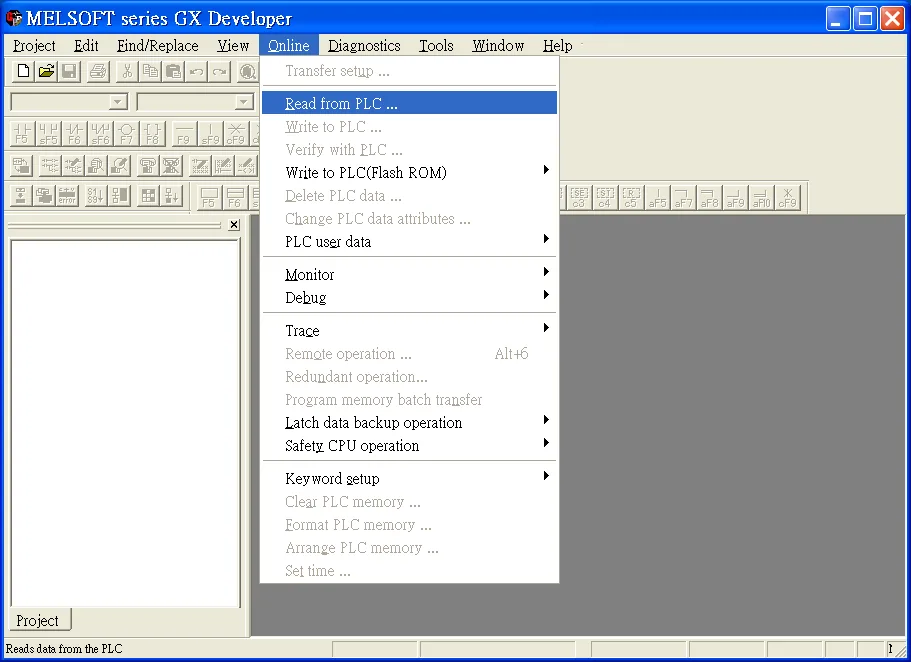
Select PLC Series
In the Select PLC series dialog, chooseQnACPUand click OK.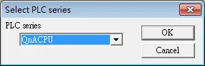
Configure Ethernet Board PC Side
Navigate to Ethernet board u0026gt; PC side I/F Ethernet board setting. Set the Network No. and Station No. as required, then click OK.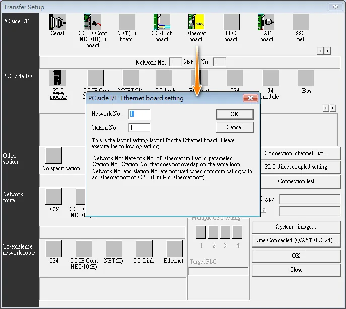
Configure Ethernet Module PLC Side
Navigate to Ethernet module u0026gt; PC side I/F detailed setting of Ethernet module. Set PLC toQJ71E71, Network No., Station No., and IP address (e.g.192.168.200.1), then click OK.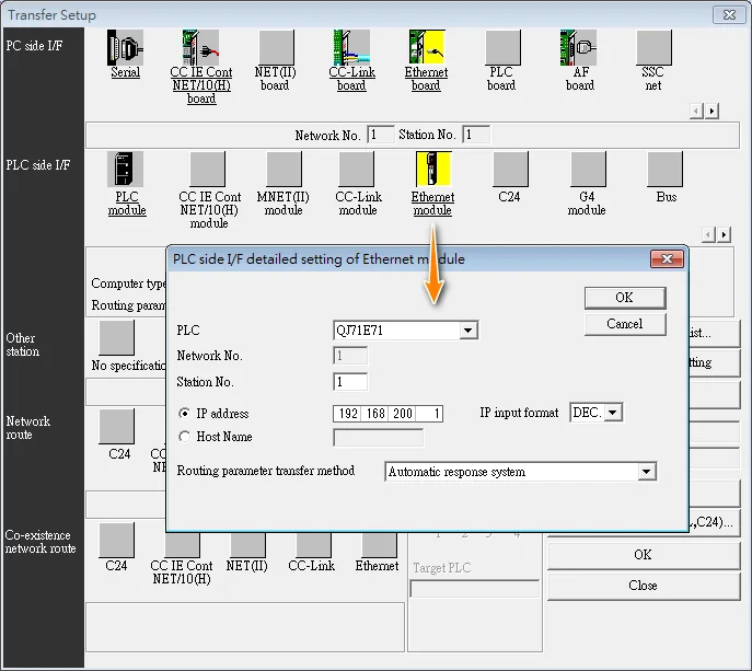
Select Co-existence Network Route
Under Other station, select Other station (Co-existence network). Under Network route, select Ethernet. Under Co-existence network route, select CC-Link.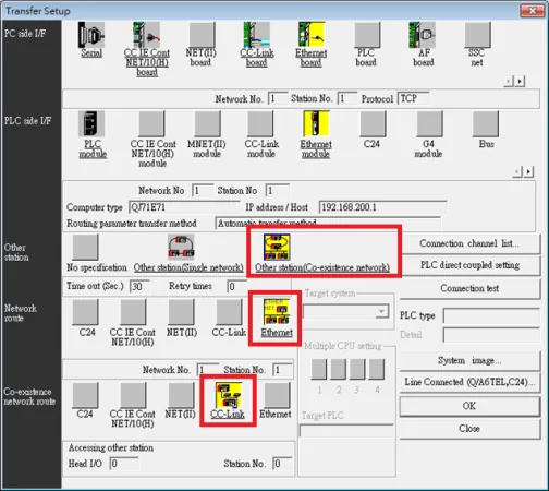
Run Connection Test
Click Connection test. A dialog confirms Successfully connected with the Q4ACPU. Click OK to close.
Device Address
| Bit/Word | Device Type | Format | Range | Memo |
|---|---|---|---|---|
| B | X | HHHH | 0 ~ 1fff | |
| B | Y | HHHH | 0 ~ 1fff | |
| B | M | DDDDD | 0 ~ 10239 | |
| B | L | DDDD | 0 ~ 8191 | |
| B | F | DDDD | 0 ~ 2047 | |
| B | V | DDDD | 0 ~ 2047 | |
| B | B | HHHH | 0 ~ 1fff | |
| B | SM | DDDD | 0 ~ 2047 | |
| B | SB | HHH | 0 ~ 7ff | |
| B | DX | HHH | 0 ~ fff | |
| B | DY | HHH | 0 ~ fff | |
| B | D_Bit | DDDDDh | 0 ~ 12287f | h: bit no. (0~f) |
| B | ZR_Bit | DDDDDDDh | 0 ~ 1042431f | h: bit no. (0~f) |
| B | TC | DDDD | 0 ~ 2047 | |
| B | TS | DDDD | 0 ~ 2047 | |
| B | CC | DDDD | 0 ~ 1023 | |
| B | CS | DDDD | 0 ~ 1023 | |
| B | STC | DD | 0 ~ 63 | |
| B | STS | DD | 0 ~ 63 | |
| B | D | DDDDD | 0 ~ 12287 | |
| W | W | HHHH | 0 ~ 1fff | |
| W | SW | HHH | 0 ~ 7ff | |
| W | R | DDDDD | 0 ~ 32767 | |
| W | SD | DDDD | 0 ~ 2047 | |
| W | Z | DD | 0 ~ 15 | |
| W | ZR | DDDDDDD | 0 ~ 1042431 | |
| W | TN | DDDD | 0 ~ 2047 | |
| W | CN | DDDD | 0 ~ 1023 | |
| W | STN | DD | 0 ~ 63 |
Wiring Diagram
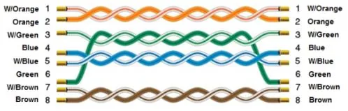
The diagram below shows the Ethernet cable wiring.