Introduction
All Maple Systems HMIs programmed with EBPro (EasyBuilder Pro), including every cMT X Series and cMT Series model, are compatible with a Mitsubishi FX5U — ASCII Mode (Ethernet). Configure your Controller and HMI/cMT with the following parameters to establish reliable communication.
Supported Series: Mitsubishi FX5U ethernet module
Website: www.mitsubishi-automation.com
HMI Setting
| Parameters | Recommended | Options | Notes |
|---|---|---|---|
| PLC type | Mitsubishi FX5U – ASCII Mode (Ethernet) | ||
| PLC I/F | Ethernet | ||
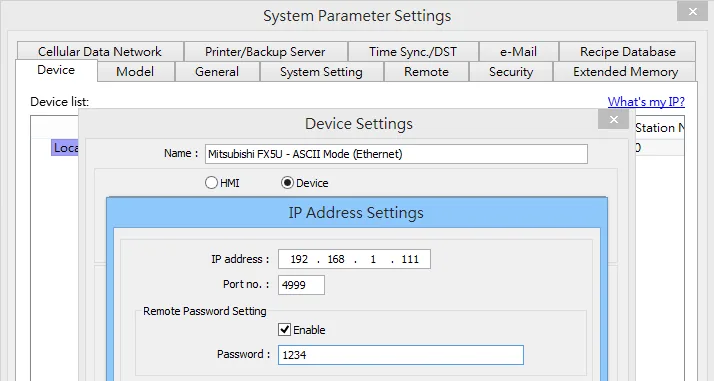
| Port no. | Set identically to the PLC | Advised to set port no. to 4999 | |
| PLC sta. no. | 255 | ||
| Network number | 0 | 0~999 | |
| Online simulator | YES |
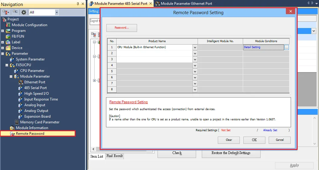
NOTE: Set a remote password and a target connection in the engineering tool, and write the data to the CPU module. Navigate to: Navigation Window => [Parameter] => [Remote Password] => [Remote Password Setting] Screen.
PLC Setting
| Communication Data Code | Value |
|---|---|
| Communication Data Code | ASCII (X, Y OCT) |
NOTE: ASCII (X,Y HEX) is not supported.
Ethernet Configuration
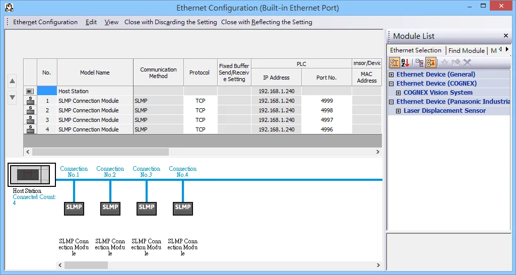
To connect PLC with multiple HMIs, Port No. must be set. In GX Works3, follow these steps: Project -> Parameter -> FX5UCPU -> Module Parameter -> Ethernet Port -> Setting Item -> External Device Configuration -> Detailed Setting.
Import Tags
GX Works3 Export Tags
Open Global Label context menu
In GX Works3, navigate to Project -u0026gt; Label -u0026gt; Global Label -u0026gt; Global, then right-click to open the context menu.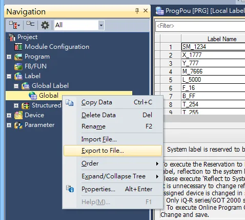
Export to XML file
In the Export to File dialog, select Export to XML File (includes assignment device of structures and structure arrays), then click Execute.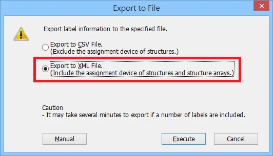
EBPro (EasyBuilder Pro) Import Tags
Click Import Tags button
After setting the System Parameters and creating the driver, click Import Tags at the bottom of the Device tab.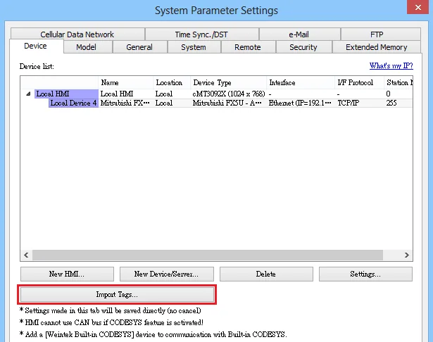
Select XML file and tags
Select the.XMLfile exported from GX Works3, then select the tags you want to import from the Add Tags dialog.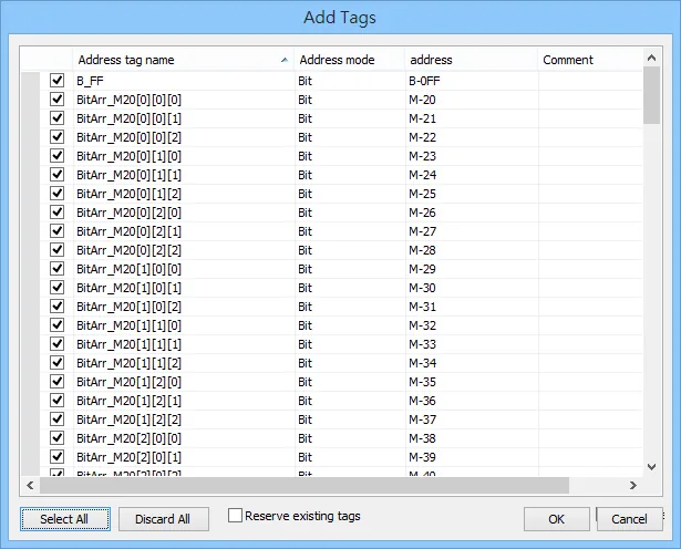
Confirm successful import
EBPro (EasyBuilder Pro) confirms the import with a success message. Click OK to dismiss.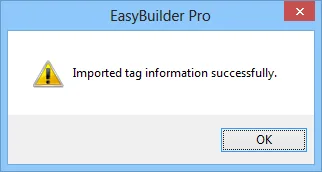
Limitations
- Structure in structure and array in structure are not supported.
- If
TN,CN,LCN,SN, and other addresses are used in the structure, three members of Contact, Coil, and Current Value will be automatically generated. - The String type will end with
0x00. If the length is set to 16 words, then a complete string will be 17 words in length. - Support data type list:
| Data Type | Support |
|---|---|
| Bit | Yes |
| Word [Unsigned] / Bit String [16-bit] | Yes |
| Double Word [Unsigned] / Bit String [32-bit] | Yes |
| Word [Signed] | Yes |
| Double Word [Signed] | Yes |
| FLOAT [Single Precision] | Yes |
| Time | Yes |
| String(32) | Yes |
| Pointer | No |
| Timer | Yes |
| Counter | Yes |
| Long Counter | Yes |
| Retentive Timer | Yes |
Device Address
| Bit/Word | Device Type | Format | Range | Memo |
|---|---|---|---|---|
| B | SM | DDDD | 0 ~ 9999 | Special Relay |
| B | X | OOOO | 0 ~ 1777 | Input Relay |
| B | Y | OOOO | 0 ~ 1777 | Output Relay |
| B | M | DDDDD | 0 ~ 32767 | Internal Relay |
| B | L | DDDDD | 0 ~ 32767 | Latch Relay |
| B | F | DDDDD | 0 ~ 32767 | Annunciator |
| B | B | HHHH | 0 ~ 7FFF | Link Relay |
| B | TS | DDDD | 0 ~ 1023 | Timer Contact |
| B | TC | DDDD | 0 ~ 1023 | Timer Coil |
| B | SS | DDDD | 0 ~ 1023 | Retentive Timer Contact |
| B | SC | DDDD | 0 ~ 1023 | Retentive Timer Coil |
| B | CS | DDDD | 0 ~ 1023 | Counter Contact |
| B | CC | DDDD | 0 ~ 1023 | Counter Coil |
| B | SB | HHHH | 0 ~ 7FFF | Special Link Relay |
| B | S | DDDD | 0 ~ 4095 | Step Relay |
| B | D_Bit | DDDDh | 0 ~ 7999F | Data Register Bit |
| B | SD_bit | DDDDDh | 0 ~ 11999F | Special Register Bit |
| B | R_bit | DDDDDh | 0 ~ 32767F | File Register Bit |
| B | SW_bit | HHHHh | 0 ~ 7FFFF | Special Link Register Bit |
| B | W_bit | HHHHh | 0 ~ 7FFFF | Link Register Bit |
| DW | LZ | D | 0 ~ 1 | Long Index Register |
| W | SD | DDDDD | 0 ~ 11999 | Special Register |
| W | D | DDDD | 0 ~ 7999 | Data Register |
| W | R | DDDDD | 0 ~ 32767 | File Register |
| W | W | HHHH | 0 ~ 7FFF | Link Register |
| W | TN | DDDD | 0 ~ 1023 | Timer Current Value |
| W | SN | DDDD | 0 ~ 1023 | Retentive Timer Current Value |
| W | CN | DDDD | 0 ~ 1023 | Counter Current Value |
| W | SW | HHHH | 0 ~ 7FFF | Special Link Register |
| W | Z | DD | 0 ~ 19 | Index Register |
Wiring Diagram
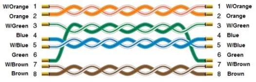
The diagram below shows the Ethernet cable wiring.