Introduction
All Maple Systems HMIs programmed with EBPro (EasyBuilder Pro), including every cMT X Series and cMT Series model, are compatible with a Mitsubishi FX3U (Ethernet). Configure your Controller and HMI/cMT with the following parameters to establish reliable communication.
Supported Series: Mitsubishi FX SERIES, Module: FX3U-ENET, FX3U-ENET-ADP
Website: http://www.mitsubishi-automation.com
HMI Settings
| Parameters | Recommended | Options | Notes |
|---|---|---|---|
| PLC type | Mitsubishi FX3U (Ethernet) | ||
| PLC I/F | Ethernet | ||
| Port no. | 5001 (default) | Refer to Module Setting | |
| PLC sta. no. | 0 (default) | Refer to Module Setting |
PLC Settings
FX3U-ENET Module Setting
Before using the Ethernet module, use GX Developer / FX Configurator-EN to configure the Ethernet module. The FX3U-ENET module setting steps are shown below.
Open GX Developer Online menu
Open GX Developer and select Read from PLC in the Online menu.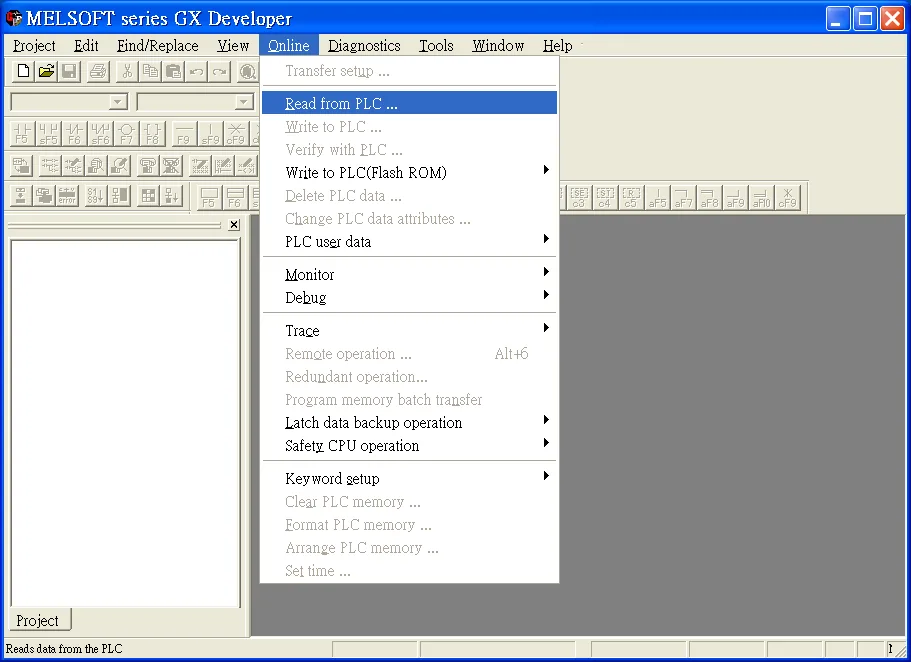
Select FXCPU PLC series
In the Select PLC series dialog, choose FXCPU and click OK.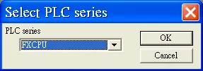
Connect PLC via serial port
Connect the PLC via serial port to set the IP address. In the Transfer Setup window, select RS-232C as the PC side I/F serial setting, set COM port toCOM 1, and set Transmission speed to115.2Kbps.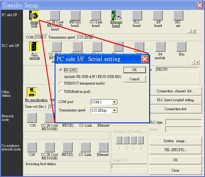
Open FX Configurator-EN
After finishing the PLC settings, select Tools u0026gt; FX special function utility u0026gt; FX Configurator-EN.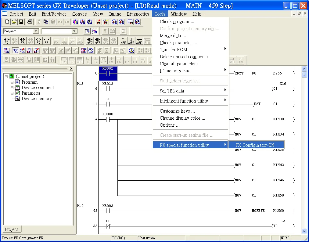
Select Module 0 in Ethernet settings
In FX Configurator-EN, select Module 0 in the Ethernet Module settings list.If more than one module is needed, set each module step by step.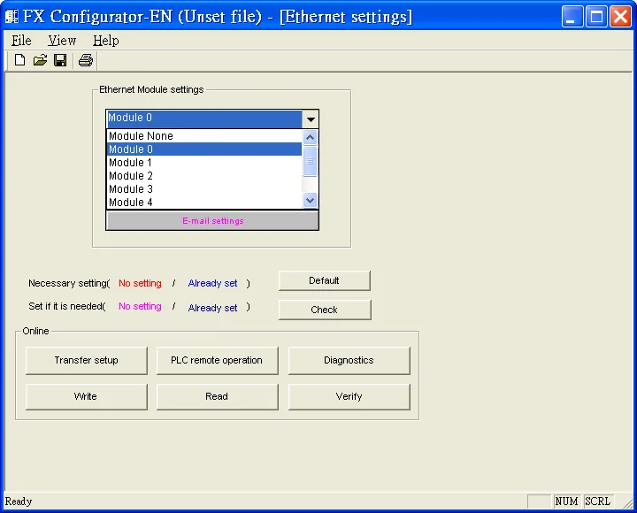
Configure Ethernet operational settings
In Ethernet operational settings, select the related parameters and IP address, then press End to finish setting.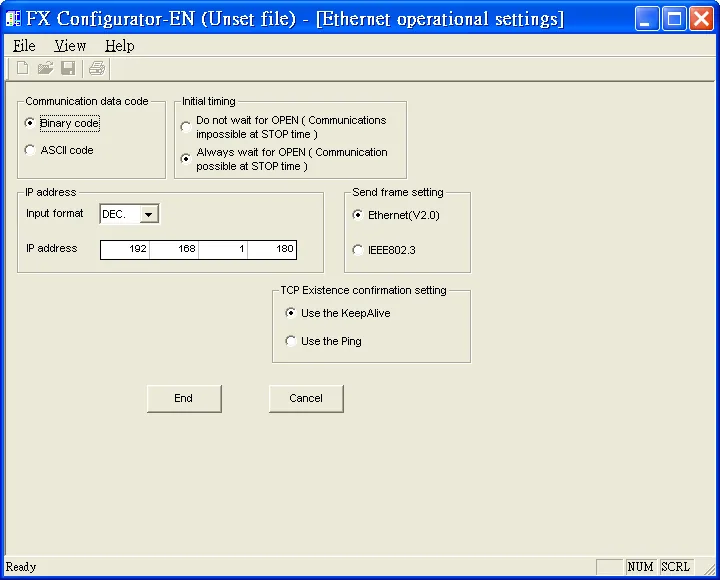
Configure Ethernet open settings
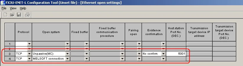
In Ethernet open settings, set the parameters below and press End.The first Protocol row uses GX Developer to communicate with the module. The maximum number of Fixed buffer communication procedure units is 4.
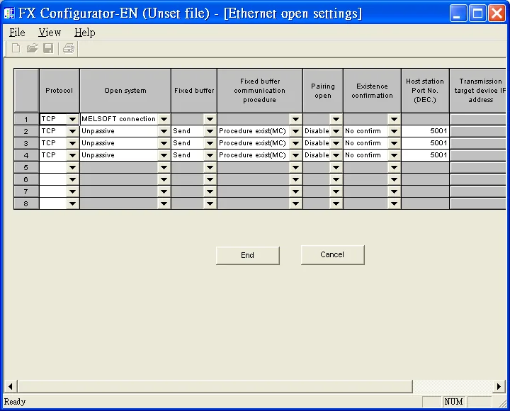
Or, for the FX3U-ENET-L module, use the FX3U-ENET-L Configuration Tool with the equivalent Ethernet open settings:
Restart and Verify Ethernet Module
Restart PLC for Ethernet communication
After setting all PLC parameters, restart the PLC to enable Ethernet communication. Verify the settings by clicking Read in FX Configurator-EN to read back from the Ethernet module.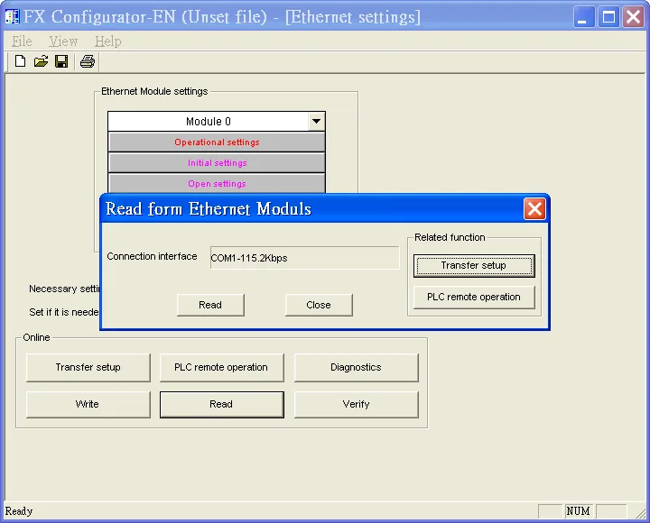
Import Tags
Export from GX Works2
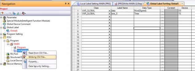
In MELSOFT Series GX Works2, navigate to Global Label Setting and select Write to CSV File to export the tag database.
Import into EBPro (EasyBuilder Pro)
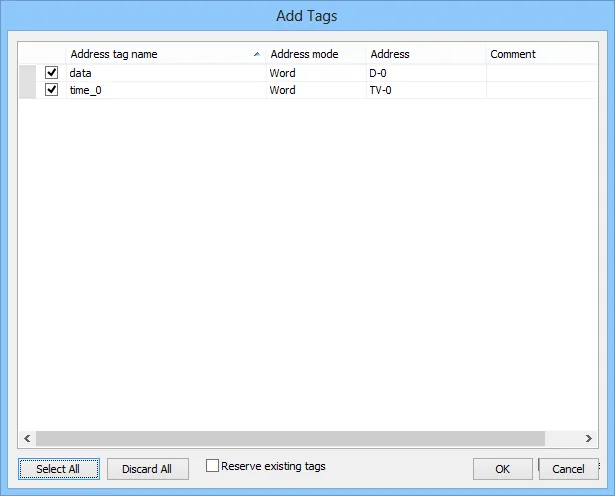
In EBPro (EasyBuilder Pro), navigate to System Parameter Settings > Device > Driver > Import Tags to import the exported CSV file.
Device Address
| Bit/Word | Device type | Format | Range | Memo |
|---|---|---|---|---|
| B | X | OOO | 0 ~ 571 | Input |
| B | Y | OOO | 0 ~ 571 | Output Relay |
| B | M | DDDD | 0 ~ 7999 | Internal Relay |
| B | T | DDD | 0 ~ 511 | Timer Contacts |
| B | C | DDD | 0 ~ 255 | Counter Contacts |
| B | SM | DDDD | 8000 ~ 8511 | Special Int. Relays |
| B | D_Bit | DDDDDdd | 0 ~ 1799915 | Data Register Bit Access |
| B | S | DDDD | 0 ~ 4095 | Step Relays |
| W | TV | DDD | 0 ~ 511 | Timer Value |
| W | CV | DDD | 0 ~ 199 | Counter Value |
| W | D | DDDD | 0 ~ 7999 | Data Registers |
| W | CV2 | DDD | 200 ~ 255 | Counter Value |
| W | SD | DDDD | 8000 ~ 8511 | Special Data Registers |
| W | R | DDDDD | 0 ~ 32767 | File Register |
Wiring Diagram
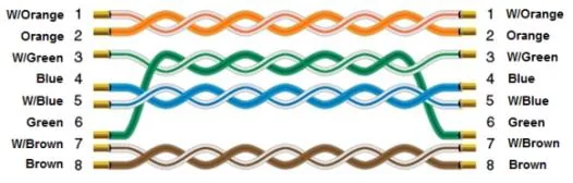
NOTE: Use a standard straight-through Ethernet cable to connect the HMI to the FX3U-ENET module.
The diagram below shows the Ethernet cable wiring.