
Introduction
All Maple Systems HMIs programmed with EBPro (EasyBuilder Pro), including every cMT X Series and cMT Series model, are compatible with Idec Micro. Configure your Controller and HMI/cMT with the following parameters to establish reliable communication.
Supported Series: IDEC Micro3, Micro3C, OpenNet Controller series
Website: http://www.idec.com
HMI Settings
| Parameters | Recommended | Options | Notes |
|---|---|---|---|
| PLC type | IDEC Micro | ||
| PLC I/F | RS232 | RS232, RS485 | |
| Baud rate | 9600 | 9600, 19200 | |
| Data bits | 7 | 7, 8 | |
| Parity | Even | Even, Odd, None | |
| Stop bits | 1 | 1 | |
| PLC sta. no. | 255 (for 1:1 connect) | 0-255 | 255 or same as the PLC setting |
| Online simulator | YES | ||
| Extend address mode | YES | Do not set the PLC Station No. to 255 |
PLC Settings
| Parameters | Recommended |
|---|---|
| Communication mode | 9600, E, 7, 1 (default), Use Computer Link Protocol |
Device Address
| Bit/Word | Device type | Format | Range | Memo |
|---|---|---|---|---|
| B | X | DDDDo | 0 ~ 20477 | Input (I) |
| B | Y | DDDDo | 0 ~ 20477 | Output (Q) |
| B | M | DDDDo | 0 ~ 20477 | Internal Relay (M) |
| W | RT | DDDD | 0 ~ 9999 | Timer (T) |
| W | RC | DDDD | 0 ~ 9999 | Counter (C) |
| W | D | DDDD | 0 ~ 9999 | Data Register (D) |
Wiring Diagrams
NOTE: The serial port pin assignments may vary between HMI models.
Diagram 1: RS-232 (Micro3C, MicroSmart, OpenNet Controller CPU Ladder Port)
The following is the view from the soldering point of a connector.

| HMI | Direction | PLC |
|---|---|---|
| Pin assignments | Port1 or Port2 8P Mini-DIN Male | |
| Rx | ↔ (bidirectional) | 3 |
| Tx | ↔ (bidirectional) | 4 |
| GND | ↔ (bidirectional) | 7 |
Diagram 2: RS-485 2W (Micro3 CPU Port, MicroSmart with FC4A-PC2 RS485 Communication Adapter)
The following is the view from the soldering point of a connector.
| HMI | Direction | PLC |
|---|---|---|
| Pin assignments | RS485 8P Mini-DIN Male | |
| Data- | ↔ (bidirectional) | 2 |
| Data+ | ↔ (bidirectional) | 1 |
| GND | ↔ (bidirectional) | 7 |
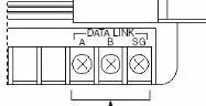
Diagram 3: RS-485 2W (Micro3C, OpenNet Controller Data Link Terminals, MicroSmart with FC4A-PC3 RS485 Communication Adapter)
The view from the soldering point of a connector
| HMI | Direction | PLC |
|---|---|---|
| Pin assignments | Data Link Terminal | |
| Data- | ↔ (bidirectional) | A |
| Data+ | ↔ (bidirectional) | B |
| GND | ↔ (bidirectional) | SG |