Introduction
All Maple Systems HMIs programmed with EBPro (EasyBuilder Pro), including every cMT X Series and cMT Series model, are compatible with Dongbu Robot iM-U Series (Ethernet). Configure your Controller and HMI/cMT with the following parameters to establish reliable communication.
HMI Settings
| Parameters | Recommended | Options | Notes |
|---|---|---|---|
| PLC type | Dongbu Robot iM-U Series (Ethernet) | ||
| PLC I/F | Ethernet | ||
| Port no. | 9007 |
Device Address
| Bit/Word | Device type | Format | Range | Memo |
|---|---|---|---|---|
| B | STAT1_Bit | Do | 0 ~ 27 | Channel system status *Read only *Note1 |
| B | STAT2_Bit | Do | 0 ~ 27 | Channel system status *Read only *Note1 |
| B | STAT3_Bit | Do | 0 ~ 27 | Channel system status *Read only *Note1 |
| B | STAT4_Bit | Do | 0 ~ 27 | Channel system status *Read only *Note1 |
| B | STATA1_Bit | DDo | 0 ~ 527 | Channel axis system status *Read only D: Axis: 0~5 D: Index: 0~2 *Note2 |
| B | STATA2_Bit | DDo | 0 ~ 527 | Channel axis system status *Read only D: Axis: 0~5 D: Index: 0~2 *Note2 |
| B | STATA3_Bit | DDo | 0 ~ 527 | Channel axis system status *Read only D: Axis: 0~5 D: Index: 0~2 *Note2 |
| B | STATA4_Bit | DDo | 0 ~ 527 | Channel axis system status *Read only D: Axis: 0~5 D: Index: 0~2 *Note2 |
| B | SYS_Bit | Do | 0 ~ 27 | System status information *Read only *Note3 |
| B | JDIR1 | D | 0 ~ 5 | JOG movement execution (CW/CCW) *Write only ON (CW) OFF (CCW) |
| B | JDIR2 | D | 0 ~ 5 | |
| B | JDIR3 | D | 0 ~ 5 | |
| B | JDIR4 | D | 0 ~ 5 | |
| B | JCW1 | D | 0 ~ 5 | JOG movement execution (CW) *Write only ON (Jog CW direction movement) OFF (Jog stop) |
| B | JCW2 | D | 0 ~ 5 | |
| B | JCW3 | D | 0 ~ 5 | |
| B | JCW4 | D | 0 ~ 5 | |
| B | JCCW1 | D | 0 ~ 5 | JOG movement execution (CCW) *Write only ON (Jog CCW direction movement) OFF (Jog stop) |
| B | JCCW2 | D | 0 ~ 5 | |
| B | JCCW3 | D | 0 ~ 5 | |
| B | JCCW4 | D | 0 ~ 5 | |
| B | MPG | D | 1 ~ 4 | MPG ON/OFF |
| B | ALM | D | 0 ~ 4 | Alarm triggering/cancellation *Write only (on trigger) |
| B | SERVO | D | 1 ~ 4 | Servo ON/OFF *Write only (on trigger) |
| B | PALL | D | 1 ~ 4 | Program full run *Write only (on trigger) |
| B | PLIN | D | 1 ~ 4 | Program line run *Write only (on trigger) |
| B | PSTOP | D | 1 ~ 4 | Program stop *Write only (on trigger) |
| B | PNEW | D | 1 ~ 4 | Program restart *Write only (on trigger) |
| B | PRES | D | 1 ~ 4 | Program reset *Write only (on trigger) |
| B | SEQS | D | 0 | System sequence execution *Write only ON: execution OFF: stop |
| B | SEQU | D | 0 | User sequence execution *Write only ( _SEQU_F)ON: execution OFF: stop |
| B | RSTOP | D | 1 ~ 4 | Stop robot movement *Write only ON: trigger |
| B | RORG | D | 1 ~ 4 | Robot origin run *Write only ON: trigger |
| B | AMCA | D | 1 ~ 4 | Coordinate value JOINT-PTP *Write only ON: arm posture right OFF: arm posture left |
| B | AMCB | D | 1 ~ 4 | Coordinate value JOINT-LINEAR *Write only ON: arm posture right OFF: arm posture left |
| B | AMCC | D | 1 ~ 4 | Coordinate value JOINT-ARC *Write only ON: arm posture right OFF: arm posture left |
| B | AMCD | D | 1 ~ 4 | Coordinate value JOINT-CIRCLE *Write only ON: arm posture right OFF: arm posture left |
| B | AMCE | D | 1 ~ 4 | Coordinate value XYZ-PTP *Write only ON: arm posture right OFF: arm posture left |
| B | AMCF | D | 1 ~ 4 | Coordinate value XYZ-LINEAR *Write only ON: arm posture right OFF: arm posture left |
| B | AMCG | D | 1 ~ 4 | Coordinate value XYZ-ARC *Write only ON: arm posture right OFF: arm posture left |
| B | AMCH | D | 1 ~ 4 | Coordinate value XYZ-CIRCLE *Write only ON: arm posture right OFF: arm posture left |
| B | AMLA | D | 1 ~ 4 | Positional variable PTP *Write only ON: trigger |
| B | AMLB | D | 1 ~ 4 | Positional variable LINEAR *Write only ON: trigger |
| B | AMLC | D | 1 ~ 4 | Positional variable ARC *Write only ON: trigger |
| B | AMLD | D | 1 ~ 4 | Positional variable CIRCLE *Write only ON: trigger |
| B | AMPA | D | 1 ~ 4 | Point file PTP *Write only ON: trigger |
| B | AMPB | D | 1 ~ 4 | Point file LINEAR *Write only ON: trigger |
| B | AMPC | D | 1 ~ 4 | Point file ARC *Write only ON: trigger |
| B | AMPD | D | 1 ~ 4 | Point file CIRCLE *Write only ON: trigger |
| B | RMCA | D | 1 ~ 4 | Coordinate value JOINT-PTP *Write only ON: arm posture right OFF: arm posture left |
| B | RMCB | D | 1 ~ 4 | Coordinate value JOINT-LINEAR *Write only ON: arm posture right OFF: arm posture left |
| B | RMCE | D | 1 ~ 4 | Coordinate value XYZ-PTP *Write only ON: arm posture right OFF: arm posture left |
| B | RMCF | D | 1 ~ 4 | Coordinate value XYZ-LINEAR *Write only ON: arm posture right OFF: arm posture left |
| B | RMLA | D | 1 ~ 4 | Positional variable PTP *Write only ON: trigger |
| B | RMLB | D | 1 ~ 4 | Positional variable LINEAR *Write only ON: trigger |
| B | RMPA | D | 1 ~ 4 | Point file PTP *Write only ON: trigger |
| B | RMPB | D | 1 ~ 4 | Point file LINEAR *Write only ON: trigger |
| B | IO_Bit | DDDo | 0 ~ 9987 | I/O contact |
| B | FDLT | D | 0 | Delete File execution *Write only ON: trigger |
| B | FCPY | D | 0 | Copy file ID execution *Write only ON: trigger |
| W | STAT1 | D | 0 ~ 2 | Channel system status *Read only |
| W | STAT2 | D | 0 ~ 2 | |
| W | STAT3 | D | 0 ~ 2 | |
| W | STAT4 | D | 0 ~ 2 | |
| W | STATA1 | DD | 0 ~ 52 | Channel axis system status *Read only D: Axis: 0~5 D: Index: 0~2 |
| W | STATA2 | DD | 0 ~ 52 | |
| W | STATA3 | DD | 0 ~ 52 | |
| W | STATA4 | DD | 0 ~ 52 | |
| W | SYS | D | 0 ~ 2 | System status information *Read only |
| W | ERR | D | 1 ~ 4 | Channel error code *Read only |
| W | ERRSUB | D | 1 ~ 4 | Channel error code (auxiliary) *Read only |
| W | JMOV | D | 1 ~ 4 | JOG move 0: Continuous jog 1: Inch jog |
| W | JMOT | D | 1 ~ 4 | JOG motion 0: XY 1: Joint |
| W | JSPD | D | 1 ~ 4 | JOG speed 0~3 |
| W | JMSPD | D | 1 ~ 4 | JOG movement speed 1~100 |
| W | MPGA | D | 1 ~ 4 | MPG connecting axis 0~5 |
| DW | ARCH | D | 1 ~ 4 | ARCH |
| DW | MECD1 | D | 0 ~ 5 | Motor current position (Encoder) *Read only |
| DW | MECD2 | D | 0 ~ 5 | |
| DW | MECD3 | D | 0 ~ 5 | |
| DW | MECD4 | D | 0 ~ 5 | |
| DW | MJIT1 | D | 0 ~ 5 | Motor current position (Joint) *Read only |
| DW | MJIT2 | D | 0 ~ 5 | |
| DW | MJIT3 | D | 0 ~ 5 | |
| DW | MJIT4 | D | 0 ~ 5 | |
| DW | MXY1 | D | 0 ~ 5 | Motor current position (XY) *Read only |
| DW | MXY2 | D | 0 ~ 5 | |
| DW | MXY3 | D | 0 ~ 5 | |
| DW | MXY4 | D | 0 ~ 5 | |
| DW | MSPD1 | D | 0 ~ 5 | Motor current speed |
| DW | MSPD2 | D | 0 ~ 5 | |
| DW | MSPD3 | D | 0 ~ 5 | |
| DW | MSPD4 | D | 0 ~ 5 | |
| W | PID | D | 1 ~ 4 | Driving file ID |
| W | _SEQU_F | D | 0 | User sequence file ID Local ( SEQU) |
| W | SEQUID | D | 0 | User sequence file ID *Read only |
| W | RSPD | D | 1 ~ 4 | Robot movement speed 1~100 |
| W | _AMC1 | D | 0 ~ 5 | Reference coordinate value Local ( AMCA~AMCH)_AMC1 for joint_AMC2 for XYZ |
| W | _AMC2 | D | 0 ~ 5 | |
| W | _AML | D | 1 ~ 2 | Reference positional variable Local ( AMLA~AMLD) |
| W | _AMP | D | 1 ~ 2 | Reference point number Local ( AMPA~AMPD) |
| W | _AMP_F | D | 0 | Reference point file ID Local ( AMPA~AMPD) |
| W | _RMC | D | 0 ~ 5 | Reference coordinate value Local ( RMCA~RMCF) |
| W | _RML | D | 0 | Reference positional variable Local ( RMLA~RMLB) |
| W | _RMP | D | 0 | Reference point number Local ( RMPA~RPMB) |
| W | _RMP_F | D | 0 | Reference point file ID Local ( RMPA~RPMB) |
| W | IO | DDD | 0 ~ 998 | I/O contact |
| DW | GINT | DDD | 0 ~ 998 | Integer variable |
| DW | GFLT | DDD | 0 ~ 998 | Real variable |
| DW | POSA0 | DDD | 0 ~ 998 | Position type variable (axis/position) |
| DW | POSA1 | DDD | 0 ~ 998 | |
| DW | POSA2 | DDD | 0 ~ 998 | |
| DW | POSA3 | DDD | 0 ~ 998 | |
| DW | POSA4 | DDD | 0 ~ 998 | |
| DW | POSA5 | DDD | 0 ~ 998 | |
| DW | POSA6 | DDD | 0 ~ 998 | |
| DW | PNTA0 | DDD | 0 ~ 999 | Point file (Axis/position) |
| DW | PNTA1 | DDD | 0 ~ 999 | |
| DW | PNTA2 | DDD | 0 ~ 999 | |
| DW | PNTA3 | DDD | 0 ~ 999 | |
| DW | PNTA4 | DDD | 0 ~ 999 | |
| DW | PNTA5 | DDD | 0 ~ 999 | |
| DW | PNTA6 | DDD | 0 ~ 999 | |
| W | _PNTA_F | D | 0 | Point file file ID |
| W | _PNTA_CH | D | 0 | Point file channel |
| W | _FDLT_F | D | 0 | Delete File File ID |
| W | _FCPY_SF | D | 0 | Copy file ID Source file id |
| W | _FCPY_CH | D | 0 | Copy file ID Destination channel |
| W | _FCPY_DF | D | 0 | Copy file ID Destination file id |
| DW | PAR | DDDD | 0 ~ 9999 | Parameter DD: Field DD: Index Fill up all field by 0 |
| DW | PARV | D | 0 | Parameter version *Read only |
Note 1: STAT1_Bit Channel System Status
It means the bit-by-bit contents of the information index as follows.
| Index | Bit pos | Contents | Comment |
|---|---|---|---|
| 0 | 0 | Active | Indicates channel activation status |
| 0 | 1 | Run | Indicates that it is running (motion, origin, jog, etc.) |
| 0 | 2 | Pgmload | Indicates that motion program compilation was successfully executed and loaded. |
| 0 | 3 | PgmAbStop | Indicates that the motion program was abnormally terminated. |
| 0 | 4 | Undefined | |
| 0 | 5 | ServoOn | Indicates the servo On/Off status of the axis |
| 0 | 6 | OriginOK | Indicates that origin execution is complete |
| 0 | 7 | Error | Indicates that a warning has occurred in the channel. |
| 1 | 0 | InPosition | All axes of the channel are within range of the parameter InposRange. |
| 1 | 1 | InRange | All axes of the channel are within the range of parameters InRangeL and InRangeR |
| 1 | 2 | PgmRun | Indicates that motion program operation is in progress. |
| 1 | 3 | StepRun | Indicates that the motion program is executing step operation |
| 1 | 4 | DmoveRun | Indicates that motion movement is in progress. |
| 1 | 5 | OriginRun | Indicates that the origin run is in progress. |
| 1 | 6 | JogRun | Jog driving |
| 1 | 7 | Undefined | |
| 2 | 0 | Undefined | |
| 2 | 1 | Undefined | |
| 2 | 2 | Undefined | |
| 2 | 3 | Undefined | |
| 2 | 4 | Undefined | |
| 2 | 5 | Undefined | |
| 2 | 6 | Undefined | |
| 2 | 7 | Undefined |
Note 2: STATA1_Bit Channel Axis System Status
It means the bit-by-bit contents of the information index as follows.
| Index | Bit pos | Contents | Comment |
|---|---|---|---|
| 0 | 0 | Ready | Indicates that the axis motion is ready. |
| 0 | 1 | Undefined | |
| 0 | 2 | Undefined | |
| 0 | 3 | CAP | Indicates that the c-phase signal of Amp has been caught. |
| 0 | 4 | BreakOn | Indicates the magnetic break On/Off status of the axis |
| 0 | 5 | DBreakOn | Indicates the electric brake On/Off status of the shaft. |
| 0 | 6 | ServoOn | Indicates the servo On/Off status of the axis. |
| 0 | 7 | Fault | Indicates whether an error has occurred in the axis module. |
| 1 | 0 | DesirVel0 | Indicates that the command velocity is 0. Stationary state. |
| 1 | 1 | InPosition | Indicates that the axis is within range of the parameter InposRange. |
| 1 | 2 | InRange | Indicates that the axis is within the range of InRangeL and InRange of parameters. |
| 1 | 3 | Undefined | |
| 1 | 4 | Undefined | |
| 1 | 5 | Undefined | |
| 1 | 6 | Undefined | |
| 1 | 7 | Undefined | |
| 2 | 0 | FLS(soft) | Indicates whether the forward limit sensor set by software is detected. |
| 2 | 1 | RLS(soft) | Indicates whether the reverse limit sensor set by the software is detected. |
| 2 | 2 | ORG(soft) | Indicates whether origin sensor set in software is detected. |
| 2 | 3 | Undefined | |
| 2 | 4 | Undefined | |
| 2 | 5 | FLS(hard) | Indicates whether the limit sensor in the direction of encoder increase is detected. |
| 2 | 6 | RLS(hard) | Indicates whether the limit sensor in the direction of encoder decrease is detected. |
| 2 | 7 | ORG(hard) | Indicates whether origin sensor on hardware is detected. |
Note 3: SYS_Bit System Status Information
It means the bit-by-bit contents of the information index as follows.
| Index | Bit pos | Contents | Comment |
|---|---|---|---|
| 0 | 0 | FromEMG | Indicates the emergency stop input attached to the front panel of the controller. |
| 0 | 1 | TboxEMG | Indicates the emergency stop input of the teaching pendant. |
| 0 | 2 | OP EMG | Indicates emergency stop input of Operating Box |
| 0 | 3 | ||
| 0 | 4 | ||
| 0 | 5 | ||
| 0 | 6 | UserSeqRun | Indicates that a user sequence program is running. |
| 0 | 7 | SysSeqRun | Indicates that the system sequence program is running. |
| 1 | 0 | FrontKeyR | Displays the input of the STOP/RST SW attached to the front panel of the controller. |
| 1 | 1 | FrontKeyG | The input of START/ORG SW attached to the front panel of the controller is displayed. |
| 1 | 2 | FrontKey3 | Undefined |
| 1 | 3 | FrontKey4 | Undefined |
| 1 | 4 | FrontKey5 | Undefined |
| 1 | 5 | FrontKey6 | Undefined |
| 1 | 6 | Undefined | |
| 1 | 7 | Undefined | |
| 2 | 0 | Undefined | |
| 2 | 1 | Undefined | |
| 2 | 2 | Undefined | |
| 2 | 3 | Undefined | |
| 2 | 4 | Undefined | |
| 2 | 5 | Undefined | |
| 2 | 6 | ||
| 2 | 7 |
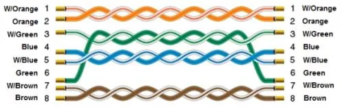
Wiring Diagram
The diagram below shows the Ethernet cable wiring.