
Introduction
All Maple Systems HMIs programmed with EBPro (EasyBuilder Pro), including every cMT X Series and cMT Series model, are compatible with BACnet MSTP. Configure your Controller and HMI/cMT with the following parameters to establish reliable communication.
Supports series: BACnet/MSTP protocol devices
HMI Settings
| Parameters | Recommended | Options | Notes |
|---|---|---|---|
| PLC type | BACnet/MSTP | ||
| PLC I/F | RS485-2W | ||
| Baud rate | 38400 | 9600, 19200, 38400 | |
| Data bits | 8 | ||
| Parity | None | ||
| Stop bits | 1 | ||
| Time out (sec) | 1.0 | 0.05 ~ 25.5 | |
| MAC | 0 | 0 ~ 254 | |
| HMI MAC | 1 | 1 ~ 127 | |
| Nmax_master | 127 | 2 ~ 127 | |
| Npoll | 50 | 1 ~ 255 | |
| Device MAC address | 1 | *Note1 | |
| Device ID | 0 | *Note1 | |
| Network Address | 0 | Use Destination Specifier *Note1 | |
| Mac Layer Address Length | 1 | Use Destination Specifier *Note1 | |
| Mac(HEX) | 0 | Use Destination Specifier *Note1 | |
| Online simulator | NO | ||
| Extend address mode | NO |
*Note1: Press “Who is” to connect to the device to automatically obtain parameters or enter parameters manually.
Parameter Settings
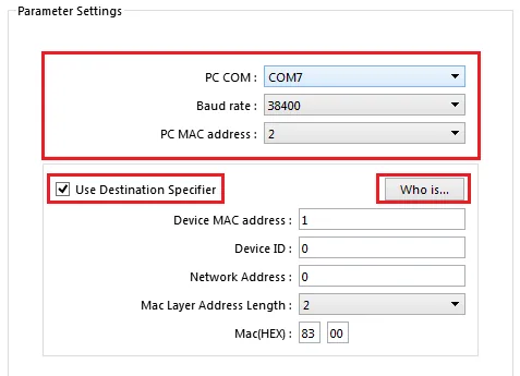
Set MSTP Parameters of PC
Connect the MSTP device to the communication port of the PC. Follow the steps below to retrieve or directly set the communication parameters of the device.
- [PC COM]: Set up the PC and device to connect to the COM port.
- [Baud rate]: Set the baud rate of the device.
- [PC MAC Address]: Set the BACnet MSTP MAC parameters of the PC. This setting item cannot be repeated with the device.
- [Who is]: Retrieve the parameters of the MSTP device connected to the PC. If it cannot be retrieved, please check the above parameter settings.
- [Use Destination Specifier]: Some MSTP devices will use [Destination Specifier], and the communication parameters need to be filled in [Network Address], [Mac Layer Address Length] and [MAC].
- [Device MAC address]: Set the MAC address of the MSTP device.
- [Device ID]: Set the ID of the MSTP device.
How to Import Tags
Add BACnet Driver and Open Tag Manager
In EBPro (EasyBuilder) System Parameter Settings add BACnet/MSTP driver, set the communication parameters, and then click the Tag Manager button.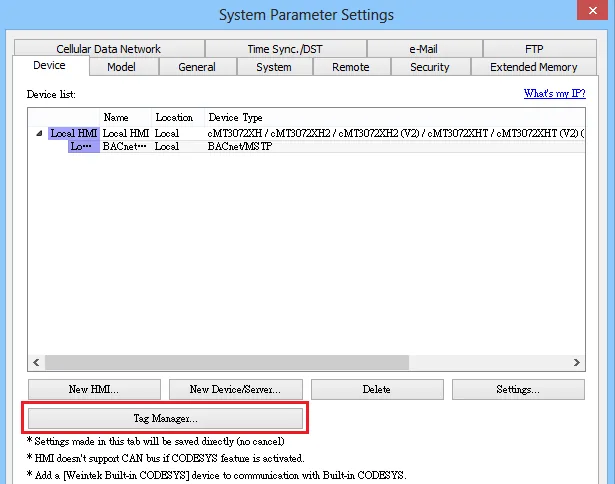
Connect Device and Scan for MAC
Use a RS-232/RS-485 converter to connect the BACnet MS/TP unit with PC. Only one BACnet MS/TP unit is allowed. Set PC COM and Baud rate, click Who is button to find the MAC address and Device ID of the BACnet MS/TP unit.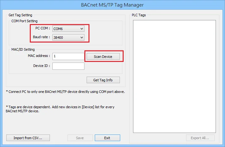
Confirm Device Found
If the device is found, the following message shows. Click OK.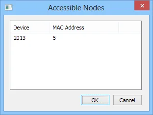
Retrieve Address Tag Info
After getting the MAC address and Device ID, click Get Tag Info button to get the address tags.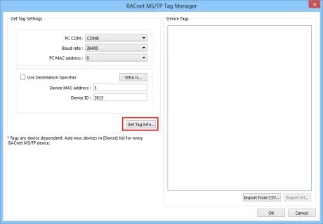
Confirm Tags Imported Successfully
If the tags are obtained successfully, the following message shows. Click OK.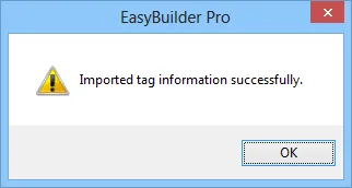
Select and Import Device Tags
In the Device Tags field, the tags with its check box selected can be imported. Click OK to complete the address import. Click Export All to save the address tags as a CSV file. If tag information cannot be obtained when creating a project, use [Import from CSV] to obtain tag information.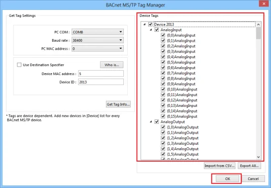
Add Additional BACnet Units
To connect another BACnet/MSTP unit, please add the BACnet/MSTP driver in EasyBuilder System Parameter Settings again. The communication parameters will follow the settings of the firstly added unit. The way to get tag information is the same as illustrated in the preceding steps. Another way to get tag information is to click [Import from CSV] button in Tag Manager.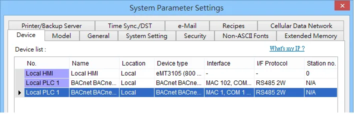
Notes:
- The MAC address and Device ID of certain BACnet MS/TP units can be gained by clicking [Scan Device] only at the first time the unit is powered up. To get this information in the same way again, please power up the unit again.
- Certain BACnet MS/TP units do not support [Scan Device] and [Get Tag Info].
- If the MAC address gained by clicking [Scan Device] does not match the one specified in EBPro (EasyBuilder Pro) Device Properties settings, a message shows as a reminder when [Get Tag Info] is clicked.
MSTP Model
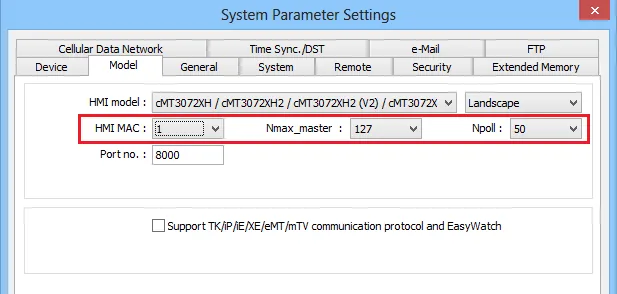
After adding the driver and importing the tag, the user needs to set the MSTP Model. The setting path is as follows: [System Parameter Settings] → [Model]
- [HMI MAC]: Set BACnet MSTP MAC parameters for HMI.
- [Nmax_master]: Set the maximum MAC in the domain.
- [Npoll]: Set the interval for sending polling packets (50 means that after receiving 50 tokens, polling will continue).
Default Object Model
NOTE: Object name cannot include “#”.
| Object ID | Object Name | Object Structure |
|---|---|---|
| 0 | Analog Input | ObjectName |
| 0 | Analog Input | ObjectIdentifier |
| 0 | Analog Input | ObjectType |
| 0 | Analog Input | PresentValue |
| 0 | Analog Input | PresentValue Array |
| 0 | Analog Input | EventState |
| 0 | Analog Input | OutOfService |
| 0 | Analog Input | Units |
| 0 | Analog Input | SubscribeCovTime |
| 0 | Analog Input | HighLimit |
| 0 | Analog Input | LowLimit |
| 0 | Analog Input | DeadBand |
| 0 | Analog Input | NotificationClass |
| 0 | Analog Input | LimitEnable |
| 0 | Analog Input | EventEnable |
| 0 | Analog Input | NotifyType |
| 0 | Analog Input | TimeDelay |
| 0 | Analog Input | AckedTransitions |
| 1 | Analog Output | ObjectName |
| 1 | Analog Output | ObjectIdentifier |
| 1 | Analog Output | ObjectType |
| 1 | Analog Output | PresentValue |
| 1 | Analog Output | PresentValueArray |
| 1 | Analog Output | EventState |
| 1 | Analog Output | OutOfService |
| 1 | Analog Output | Units |
| 1 | Analog Output | Priority |
| 1 | Analog Output | PriorityReset |
| 1 | Analog Output | PriorityArray |
| 1 | Analog Output | RelinquishDefault |
| 1 | Analog Output | HighLimit |
| 1 | Analog Output | LowLimit |
| 1 | Analog Output | DeadBand |
| 1 | Analog Output | NotificationClass |
| 1 | Analog Output | LimitEnable |
| 1 | Analog Output | EventEnable |
| 1 | Analog Output | NotifyType |
| 1 | Analog Output | TimeDelay |
| 1 | Analog Output | AckedTransitions |
| 2 | Analog Value | ObjectName |
| 2 | Analog Value | ObjectIdentifier |
| 2 | Analog Value | ObjectType |
| 2 | Analog Value | PresentValue |
| 2 | Analog Value | PresentValueArray |
| 2 | Analog Value | EventState |
| 2 | Analog Value | OutOfService |
| 2 | Analog Value | Units |
| 2 | Analog Value | Priority |
| 2 | Analog Value | PriorityReset |
| 2 | Analog Value | PriorityArray |
| 2 | Analog Value | RelinquishDefault |
| 2 | Analog Value | HighLimit |
| 2 | Analog Value | LowLimit |
| 2 | Analog Value | Dead Band |
| 2 | Analog Value | NotificationClass |
| 2 | Analog Value | LimitEnable |
| 2 | Analog Value | EventEnable |
| 2 | Analog Value | NotifyType |
| 2 | Analog Value | TimeDelay |
| 2 | Analog Value | AckedTransitions |
| 3 | Binary Input | ObjectName |
| 3 | Binary Input | ObjectIdentifier |
| 3 | Binary Input | ObjectType |
| 3 | Binary Input | PresentValue |
| 3 | Binary Input | PresentValueArray |
| 3 | Binary Input | EventState |
| 3 | Binary Input | OutOfService |
| 3 | Binary Input | Polarity |
| 3 | Binary Input | AlarmValue |
| 3 | Binary Input | NotificationClass |
| 3 | Binary Input | EventEnable |
| 3 | Binary Input | NotifyType |
| 3 | Binary Input | TimeDelay |
| 3 | Binary Input | AckedTransitions |
| 4 | Binary Output | ObjectName |
| 4 | Binary Output | ObjectIdentifier |
| 4 | Binary Output | ObjectType |
| 4 | Binary Output | PresentValue |
| 4 | Binary Output | PresentValueArray |
| 4 | Binary Output | EventState |
| 4 | Binary Output | OutOfService |
| 4 | Binary Output | Priority |
| 4 | Binary Output | PriorityReset |
| 4 | Binary Output | PriorityArray |
| 4 | Binary Output | Polarity |
| 4 | Binary Output | AlarmValue |
| 4 | Binary Output | NotificationClass |
| 4 | Binary Output | EventEnable |
| 4 | Binary Output | NotifyType |
| 4 | Binary Output | TimeDelay |
| 4 | Binary Output | AckedTransitions |
| 4 | Binary Output | RelinquishDefault |
| 5 | Binary Value | ObjectName |
| 5 | Binary Value | ObjectIdentifier |
| 5 | Binary Value | ObjectType |
| 5 | Binary Value | PresentValue |
| 5 | Binary Value | PresentValueArray |
| 5 | Binary Value | EventState |
| 5 | Binary Value | Priority |
| 5 | Binary Value | PriorityReset |
| 5 | Binary Value | PriorityArray |
| 5 | Binary Value | OutOfService |
| 5 | Binary Value | AlarmValue |
| 5 | Binary Value | NotificationClass |
| 5 | Binary Value | EventEnable |
| 5 | Binary Value | NotifyType |
| 5 | Binary Value | TimeDelay |
| 5 | Binary Value | AckedTransitions |
| 5 | Binary Value | RelinquishDefault |
| 7 | Command | ObjectName |
| 7 | Command | ObjectIdentifier |
| 7 | Command | ObjectType |
| 7 | Command | InProcess |
| 7 | Command | AllWritesSuccessful |
| 8 | Device | ObjectName |
| 8 | Device | ObjectIdentifier |
| 8 | Device | ObjectType |
| 8 | Device | SystemStatus |
| 8 | Device | VendorName |
| 8 | Device | VendorIdentifier |
| 8 | Device | ModelName |
| 8 | Device | FirmwareRevision |
| 8 | Device | ApplicationSoftwareVersion |
| 8 | Device | ProtocolVersion |
| 8 | Device | ProtocolRevision |
| 8 | Device | MaxAPDUlengthAccepted |
| 8 | Device | SegmentationSupported |
| 8 | Device | ApduTimeout |
| 8 | Device | NumberOfAPDUretries |
| 8 | Device | DataBaseRevision |
| 8 | Device | MaxSegmentsAccepted |
| 8 | Device | UtcOffset |
| 8 | Device | DaylightSavingsStatus |
| 8 | Device | ApduSegmentTimeout |
| 8 | Device | BackupFailureTimeout |
| 10 | File | ObjectName |
| 10 | File | ObjectIdentifier |
| 10 | File | ObjectType |
| 10 | File | FileType |
| 10 | File | FileSize |
| 10 | File | Archive |
| 10 | File | ReadOnly |
| 13 | Multi State Input | ObjectName |
| 13 | Multi State Input | ObjectIdentifier |
| 13 | Multi State Input | ObjectType |
| 13 | Multi State Input | PresentValue |
| 13 | Multi State Input | EventState |
| 13 | Multi State Input | OutOfService |
| 13 | Multi State Input | NumberOfStates |
| 13 | Multi State Input | AckedTransitions |
| 14 | Multi State Output | ObjectName |
| 14 | Multi State Output | ObjectIdentifier |
| 14 | Multi State Output | ObjectType |
| 14 | Multi State Output | PresentValue |
| 14 | Multi State Output | EventState |
| 14 | Multi State Output | OutOfService |
| 14 | Multi State Output | NumberOfStates |
| 14 | Multi State Output | Priority |
| 14 | Multi State Output | PriorityReset |
| 14 | Multi State Output | PriorityArray |
| 14 | Multi State Output | AckedTransitions |
| 14 | Multi State Output | RelinquishDefault |
| 16 | Program | ObjectName |
| 16 | Program | ObjectIdentifier |
| 16 | Program | ObjectType |
| 18 | Averaging | ObjectName |
| 18 | Averaging | ObjectIdentifier |
| 18 | Averaging | ObjectType |
| 18 | Averaging | MinimumValue |
| 18 | Averaging | AverageValue |
| 18 | Averaging | MaximumValue |
| 18 | Averaging | AttemptedSamples |
| 18 | Averaging | ValidSamples |
| 18 | Averaging | WindowInterval |
| 18 | Averaging | WindowSamples |
| 19 | Multi State Value | ObjectName |
| 19 | Multi State Value | ObjectIdentifier |
| 19 | Multi State Value | ObjectType |
| 19 | Multi State Value | PresentValue |
| 19 | Multi State Value | EventState |
| 19 | Multi State Value | OutOfService |
| 19 | Multi State Value | NumberOfStates |
| 19 | Multi State Value | Priority |
| 19 | Multi State Value | PriorityReset |
| 19 | Multi State Value | PriorityArray |
| 19 | Multi State Value | AckedTransitions |
| 19 | Multi State Value | RelinquishDefault |
| 20 | Trend Log | ObjectName |
| 20 | Trend Log | ObjectIdentifier |
| 20 | Trend Log | ObjectType |
| 20 | Trend Log | Enable |
| 20 | Trend Log | StopWhenFull |
| 20 | Trend Log | BufferSize |
| 20 | Trend Log | RecordCount |
| 20 | Trend Log | TotalRecordCount |
| 21 | Life Safety Point | ObjectName |
| 21 | Life Safety Point | ObjectIdentifier |
| 21 | Life Safety Point | ObjectType |
| 21 | Life Safety Point | PresentValue |
| 21 | Life Safety Point | TrackingValue |
| 21 | Life Safety Point | EventState |
| 21 | Life Safety Point | Reliability |
| 21 | Life Safety Point | OutOfService |
| 21 | Life Safety Point | Mode |
| 21 | Life Safety Point | Silenced |
| 22 | Life Safety Zone | ObjectName |
| 22 | Life Safety Zone | ObjectIdentifier |
| 22 | Life Safety Zone | ObjectType |
| 22 | Life Safety Zone | PresentValue |
| 22 | Life Safety Zone | TrackingValue |
| 22 | Life Safety Zone | EventState |
| 22 | Life Safety Zone | Reliability |
| 22 | Life Safety Zone | OutOfService |
| 22 | Life Safety Zone | Mode |
| 22 | Life Safety Zone | Silenced |
| 23 | Accumulator | ObjectName |
| 23 | Accumulator | ObjectIdentifier |
| 23 | Accumulator | ObjectType |
| 23 | Accumulator | PresentValue |
| 23 | Accumulator | PresentValueArray |
| 23 | Accumulator | EventState |
| 23 | Accumulator | OutOfService |
| 23 | Accumulator | Scale |
| 23 | Accumulator | Units |
| 24 | Pulse Converter | ObjectName |
| 24 | Pulse Converter | ObjectIdentifier |
| 24 | Pulse Converter | ObjectType |
| 24 | Pulse Converter | PresentValue |
| 24 | Pulse Converter | EventState |
| 24 | Pulse Converter | OutOfService |
| 24 | Pulse Converter | Units |
| 24 | Pulse Converter | ScaleFactor |
| 24 | Pulse Converter | AdjustValue |
| 24 | Pulse Converter | Count |
Wiring Diagram
NOTE: The serial port pin assignments may vary between HMI models.
RS-485 2W
| HMI | Direction | PLC |
|---|---|---|
| Pin assignments | RS485 2W Terminal | |
| Data- | ↔ (bidirectional) | Data- |
| Data+ | ↔ (bidirectional) | Data+ |
| GND | ↔ (bidirectional) | GND |