Introduction
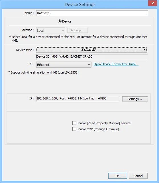
All Maple Systems HMIs programmed with EBPro (EasyBuilder Pro), including every cMT X Series and cMT Series model, are compatible with BACnet BACnet/IP. Configure your Controller and HMI/cMT with the following parameters to establish reliable communication.
HMI Setting
| Parameters | Recommended | Options | Notes |
|---|---|---|---|
| PLC type | BACnet/IP | ||
| PLC I/F | Ethernet | ||
| Port no. | 47808 | 47808 is the standard communication port of BACnet protocol. | |
| HMI port no. | 47808 | 47808~47823 49152~65535 | Different HMI ports are required when connecting multiple devices. |
| Device ID | 342566 | 0~999999 | According to device. |
| PLC sta. no. | 1 |
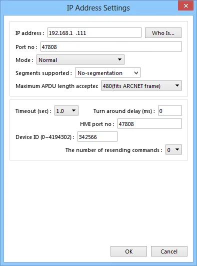
[Who is]
Scan the device in the domain and obtain the device settings.
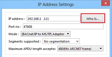
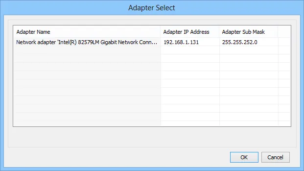
NOTE: After pressing the [Who is] button, please select the network card in the same domain as the PLC.
[Mode]
- Normal: General BACnet device
- [BACnet/IP to MS/TP] Adapter
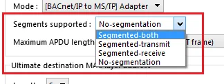
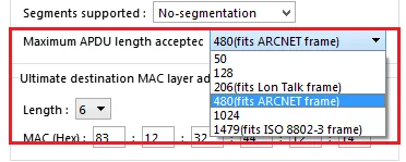
[Segments supported]
Device supports large packet segmentation.
[Maximum APDU Length accepted]
The maximum APDU length that device can support.
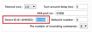
[Device ID]
0 ~ 4194302
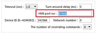
[HMI port no]
Set the communication port between HMI and device.
BACnet/IP to MS/TP Adapter Setting
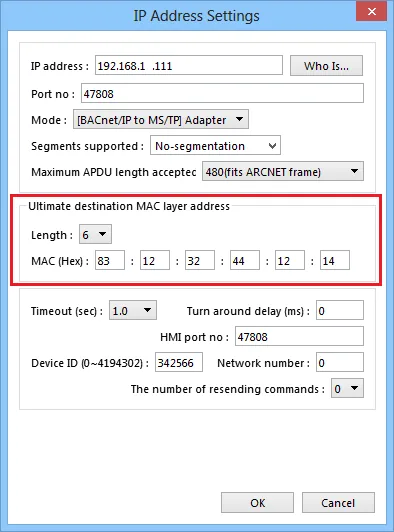
- When using BACnet/IP driver, please correctly set [Mode], [Segments supported], and [Maximum APDU length accepted] according to the actual device.
- As shown above, in BACnet/IP to MS/TP Adapter mode, [Network number] must follow the factory setting, and enter the device station number in [Device ID].
- [HMI port no]. default: 47808, can be filled in other effective value.
- [Ultimate destination MAC layer address]: Set the MAC address of the serially connected MSTP.
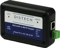
BACnet/IP to MS/TP adapter
How to Import Tags
EBPro (EasyBuilder Pro) provides two ways to gain tag addresses. One is to directly get tag information via internet, another is to export the generated CSV file via SCADA, and then import to EBPro (EasyBuilder Pro). The following introduces how to import tag address information.
Step 1. Add BACnet/IP driver in System Parameters Settings
Step 2. Correctly set the relevant parameters.
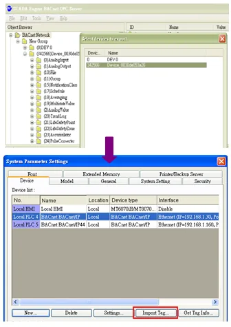
Step 3. Get tag address information
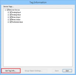
Way 1: Click Tag Manager → Get Tag Info
Way 2: Import the CSV file generated by SCADA software.
NOTE: Support files exported by BACShark software.
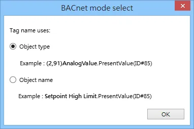
BACnet mode select: Object type or Object name
When using Get tag or import SCADA software to create a CSV file, you can select BACnet mode. (EBPro (EasyBuilder Pro) V6.04.02 and later versions support this function)
Step 4. File imported successfully.
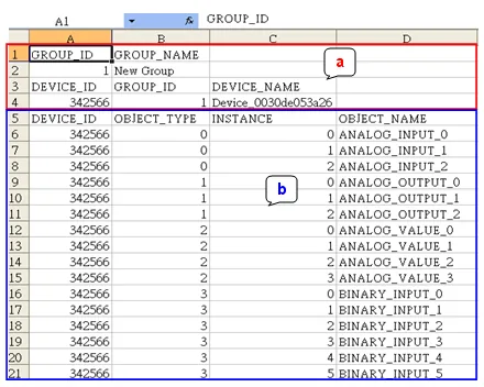
CSV file content is shown below; users can build the file and import:
- Object format
- OBJECT NAME (user defined tag name, EasyBuilder will start reading data from the 6th row of CSV file.), DEVICE ID, OBJECT TYPE (object ID) and INSTANCE (object address)
- File imported successfully message
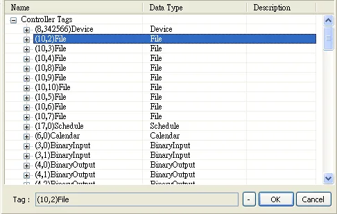
Take (10,2)File as an example, 10 represents object ID, 2 represents object address, File represents user defined name or default name.
Default Object Model
| Object ID | Object Name | Object Structure |
|---|---|---|
| 0 | Analog Input | ObjectName |
| 0 | ObjectIdentifier | |
| 0 | ObjectType | |
| 0 | PresentValue | |
| 0 | PresentValue Array | |
| 0 | EventState | |
| 0 | OutOfService | |
| 0 | Units | |
| 0 | SubscribeCovTime | |
| 0 | HighLimit | |
| 0 | LowLimit | |
| 0 | DeadBand | |
| 0 | NotificationClass | |
| 0 | LimitEnable | |
| 0 | EventEnable | |
| 0 | NotifyType | |
| 0 | TimeDelay | |
| 0 | AckedTransitions | |
| 1 | Analog Output | ObjectName |
| 1 | ObjectIdentifier | |
| 1 | ObjectType | |
| 1 | PresentValue | |
| 1 | PresentValueArray | |
| 1 | EventState | |
| 1 | OutOfService | |
| 1 | Units | |
| 1 | Priority | |
| 1 | PriorityReset | |
| 1 | PriorityArray | |
| 1 | RelinquishDefault | |
| 1 | HighLimit | |
| 1 | LowLimit | |
| 1 | DeadBand | |
| 1 | NotificationClass | |
| 1 | LimitEnable | |
| 1 | EventEnable | |
| 1 | NotifyType | |
| 1 | TimeDelay | |
| 1 | AckedTransitions | |
| 2 | Analog Value | ObjectName |
| 2 | ObjectIdentifier | |
| 2 | ObjectType | |
| 2 | PresentValue | |
| 2 | PresentValueArray | |
| 2 | EventState | |
| 2 | OutOfService | |
| 2 | Units | |
| 2 | Priority | |
| 2 | PriorityReset | |
| 2 | PriorityArray | |
| 2 | RelinquishDefault | |
| 2 | HighLimit | |
| 2 | LowLimit | |
| 2 | Dead Band | |
| 2 | NotificationClass | |
| 2 | LimitEnable | |
| 2 | EventEnable | |
| 2 | NotifyType | |
| 2 | TimeDelay | |
| 2 | AckedTransitions | |
| 3 | Binary Input | ObjectName |
| 3 | ObjectIdentifier | |
| 3 | ObjectType | |
| 3 | PresentValue | |
| 3 | PresentValueArray | |
| 3 | EventState | |
| 3 | OutOfService | |
| 3 | Polarity | |
| 3 | AlarmValue | |
| 3 | NotificationClass | |
| 3 | EventEnable | |
| 3 | NotifyType | |
| 3 | TimeDelay | |
| 3 | AckedTransitions | |
| 4 | Binary Output | ObjectName |
| 4 | ObjectIdentifier | |
| 4 | ObjectType | |
| 4 | PresentValue | |
| 4 | PresentValueArray | |
| 4 | EventState | |
| 4 | OutOfService | |
| 4 | Priority | |
| 4 | PriorityReset | |
| 4 | PriorityArray | |
| 4 | Polarity | |
| 4 | AlarmValue | |
| 4 | NotificationClass | |
| 4 | EventEnable | |
| 4 | NotifyType | |
| 4 | TimeDelay | |
| 4 | AckedTransitions | |
| 4 | RelinquishDefault | |
| 5 | Binary Value | ObjectName |
| 5 | ObjectIdentifier | |
| 5 | ObjectType | |
| 5 | PresentValue | |
| 5 | PresentValueArray | |
| 5 | EventState | |
| 5 | Priority | |
| 5 | PriorityReset | |
| 5 | PriorityArray | |
| 5 | OutOfService | |
| 5 | AlarmValue | |
| 5 | NotificationClass | |
| 5 | EventEnable | |
| 5 | NotifyType | |
| 5 | TimeDelay | |
| 5 | AckedTransitions | |
| 5 | RelinquishDefault | |
| 6 | Calendar | ObjectName |
| 6 | ObjectIdentifier | |
| 6 | ObjectType | |
| 6 | PresentValue | |
| 6 | DateList Date | |
| 6 | DateList DateRange | |
| 6 | DateList WeekDay | |
| 6 | DateListControl | |
| 6 | DateListStatus | |
| 7 | Command | ObjectName |
| 7 | ObjectIdentifier | |
| 7 | ObjectType | |
| 7 | InProcess | |
| 7 | AllWritesSuccessful | |
| 8 | Device | ObjectName |
| 8 | ObjectIdentifier | |
| 8 | ObjectType | |
| 8 | SystemStatus | |
| 8 | VendorName | |
| 8 | VendorIdentifier | |
| 8 | ModelName | |
| 8 | FirmwareRevision | |
| 8 | ApplicationSoftwareVersion | |
| 8 | ProtocolVersion | |
| 8 | ProtocolRevision | |
| 8 | MaxAPDUlengthAccepted | |
| 8 | SegmentationSupported | |
| 8 | ApduTimeout | |
| 8 | NumberOfAPDUretries | |
| 8 | DataBaseRevision | |
| 8 | MaxSegmentsAccepted | |
| 8 | UtcOffset | |
| 8 | DaylightSavingsStatus | |
| 8 | ApduSegmentTimeout | |
| 8 | BackupFailureTimeout | |
| 10 | File | ObjectName |
| 10 | ObjectIdentifier | |
| 10 | ObjectType | |
| 10 | FileType | |
| 10 | FileSize | |
| 10 | Archive | |
| 10 | ReadOnly | |
| 11 | Group | ObjectName |
| 11 | ObjectIdentifier | |
| 11 | ObjectType | |
| 11 | SettingGroup | |
| 13 | Multi State Input | ObjectName |
| 13 | ObjectIdentifier | |
| 13 | ObjectType | |
| 13 | PresentValue | |
| 13 | EventState | |
| 13 | OutOfService | |
| 13 | NumberOfStates | |
| 13 | AckedTransitions | |
| 14 | Multi State Output | ObjectName |
| 14 | ObjectIdentifier | |
| 14 | ObjectType | |
| 14 | PresentValue | |
| 14 | EventState | |
| 14 | OutOfService | |
| 14 | NumberOfStates | |
| 14 | Priority | |
| 14 | PriorityReset | |
| 14 | PriorityArray | |
| 14 | AckedTransitions | |
| 14 | RelinquishDefault | |
| 15 | Notification Class | ObjectName |
| 15 | ObjectIdentifier | |
| 15 | ObjectType | |
| 15 | NotificationClass | |
| 15 | RecipientList | |
| 15 | ControlWord (1:Read / 2:Write) | |
| 16 | Program | ObjectName |
| 16 | ObjectIdentifier | |
| 16 | ObjectType | |
| 17 | Schedule | ObjectName |
| 17 | ObjectIdentifier | |
| 17 | ObjectType | |
| 17 | PresentValue | |
| 17 | PriorityForWriting | |
| 17 | Reliability | |
| 17 | OutOfService | |
| 17 | WeeklyScheduleControl | |
| 17 | WeeklyScheduleStatus | |
| 17 | ExceptionScheduleControl | |
| 17 | ExceptionScheduleStatus | |
| 17 | ScheduleDefault | |
| 17 | WeeklySchedule_Monday | |
| 17 | WeeklySchedule_Tuesday | |
| 17 | WeeklySchedule_Wednesday | |
| 17 | WeeklySchedule_Thursday | |
| 17 | WeeklySchedule_Friday | |
| 17 | WeeklySchedule_Saturday | |
| 17 | WeeklySchedule_Sunday | |
| 17 | BACnetExceptionSchedule_Date | |
| 17 | BACnetExceptionSchedule_DateRange | |
| 17 | BACnetExceptionSchedule_WeekDay | |
| 17 | BACnetExceptionSchedule_Calendar | |
| 18 | Averaging | ObjectName |
| 18 | ObjectIdentifier | |
| 18 | ObjectType | |
| 18 | MinimumValue | |
| 18 | AverageValue | |
| 18 | MaximumValue | |
| 18 | AttemptedSamples | |
| 18 | ValidSamples | |
| 18 | Window Interval | |
| 18 | WindowSamples | |
| 19 | Multi State Value | ObjectName |
| 19 | ObjectIdentifier | |
| 19 | ObjectType | |
| 19 | PresentValue | |
| 19 | EventState | |
| 19 | OutOfService | |
| 19 | NumberOfStates | |
| 19 | Priority | |
| 19 | PriorityReset | |
| 19 | PriorityArray | |
| 19 | AckedTransitions | |
| 19 | RelinquishDefault | |
| 20 | Trend Log | ObjectName |
| 20 | ObjectIdentifier | |
| 20 | ObjectType | |
| 20 | Enable | |
| 20 | StopWhenFull | |
| 20 | BufferSize | |
| 20 | RecordCount | |
| 20 | TotalRecordCount | |
| 21 | Life Safety Point | ObjectName |
| 21 | ObjectIdentifier | |
| 21 | ObjectType | |
| 21 | PresentValue | |
| 21 | TrackingValue | |
| 21 | EventState | |
| 21 | Reliability | |
| 21 | OutOfService | |
| 21 | Mode | |
| 21 | Silenced | |
| 22 | Life Safety Zone | ObjectName |
| 22 | ObjectIdentifier | |
| 22 | ObjectType | |
| 22 | PresentValue | |
| 22 | TrackingValue | |
| 22 | EventState | |
| 22 | Reliability | |
| 22 | OutofService | |
| 22 | Mode | |
| 22 | Silenced | |
| 23 | Accumulator | ObjectName |
| 23 | ObjectIdentifier | |
| 23 | ObjectType | |
| 23 | PresentValue | |
| 23 | PresentValueArray | |
| 23 | EventState | |
| 23 | OutOfService | |
| 23 | Scale | |
| 23 | Units | |
| 24 | Pulse Converter | ObjectName |
| 24 | ObjectIdentifier | |
| 24 | ObjectType | |
| 24 | PresentValue | |
| 24 | EventState | |
| 24 | OutOfService | |
| 24 | Units | |
| 24 | ScaleFactor | |
| 24 | AdjustValue | |
| 24 | Count |
NOTE: Object name cannot include “#”.
NOTE: Group objects can only communicate when the Group_Member_List addresses are placed in the project editing screen.

Wiring Diagram
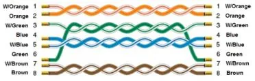
The diagram below shows the Ethernet cable wiring.