
Introduction
All Maple Systems HMI+PLCs (HMCs) programmed with MAPware7000 are compatible with any ASCII device using the Universal Serial ASCII driver. Configure your Controller and HMI+PLC (HMC) with the following parameters to establish reliable communication.
Applies to: MAPware7000
Overview
MAPware7000 supports the Universal Serial ASCII driver. Maple Systems HMI + PLC (HMCs) communicate with any device that uses the Universal Serial ASCII driver. The communication port on the ASCII device must be capable of operating as described below.
HMI+PLC (HMC) Settings
Note: The HMC uses its internal memory to buffer incoming and outgoing messages. Additionally, HMC internal memory is used to control how the messages are sent and received.
The following table lists the communications settings that must be configured in MAPware7000. These settings can be found in the Network Configuration folder for the selected project in the Project Information window:
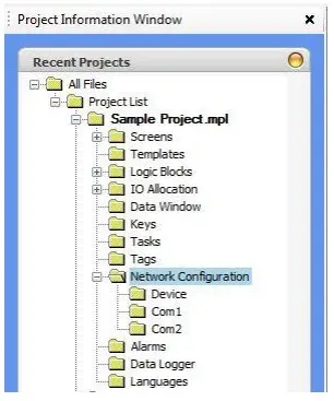
Right-click on the Com port that you wish to use to connect to the PLC, and then click Add… to display the Node Information dialog box:
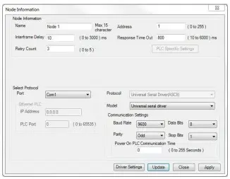
Note: You can also configure the Com ports in the Project Configuration dialog box that is displayed when creating a new project.
Please note:
- The Recommended Settings column is blank since the Universal Serial Driver can be used with any controller supporting ASCII communications. The available port may determine whether RS-232 or RS-485 should be used.
- The Options column lists MAPware7000 options; your PLC may not support every option.
| Name | Recommended Setting | Options | Important Notes |
|---|---|---|---|
| Port | No recommended option | COM1, COM2, Ethernet | This is the HMC port that the PLC is connected to |
| Protocol | Universal Serial Driver (ASCII) | All available protocol drivers, including serial printer and a universal ASCII driver | Select the appropriate protocol for your PLC |
| Model | Universal Serial Driver | ||
| Communication Setting: Baud Rate | 9600 | 4800, 9600, 19.2k, 38.4k, 57.6k, 115.2k, 187.5k | Must match the PLC serial port |
| Ethernet PLC: IP Address | Enter the IP Address that is assigned to the PLC Ethernet port | ||
| Ethernet PLC: PLC Port | Network address assigned to the PLC Ethernet port | ||
| Communication Setting: Parity | Odd | None, Even, Odd | |
| Communication Setting: Data Bits | 8 | 7, 8 | |
| Communication Setting: Stop Bits | 1 | 1, 2 | |
| Power On PLC Communication Time | 0-255 seconds | Delays communications with the PLC after applying power to the HMC | |
| Node Information: Name | Maximum of 15 characters | Provide a meaningful description to the port | |
| Node Information: Address | 0 to 255 | Assigns a network address to each PLC. Use when networking several PLCs on one COM port. | |
| Node Information: Interframe Delay | 0 to 3000 msec | Minimum time delay between commands sent to the PLC | |
| Node Information: Retry count | 0 to 5 | The maximum attempts by the HMC to resend unanswered command. | |
| Node Information: Response Time Out | 10 to 6000 msec | The time that must pass before the HMC reattempts to send an unanswered command to the PLC |
Driver Settings Dialog
Click Driver Settings to configure the Universal Serial Driver in MAPware7000. The Driver Settings dialog has three tabs – Transmit, Receive, and Settings. The various combinations of settings allows configuration of headers, trailers, and checksums, as well as status bits.
Transmit Tab
Configures the data to be transmitted (Mandatory)
Open the driver settings>transmit tab. Specify the starting register [in the Starting address field] of the data to insert into the packet. Use a D or K register.
Next, specify the address containing the number of bytes to be transmitted [in the No. of Bytes fields]. Use a D, K or @ register.
Note: Registers in the HMC products are 16 bits wide. Therefore, each register holds two ASCII characters.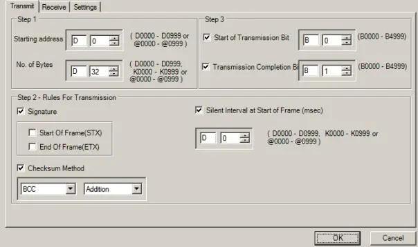
Create Rules for Transmission (Optional)
Configures the Header, Trailer, and Timing:
Signature: Configure the Start of Frame and / or End of Frame characters. When the either box is checked, a dialog will be displayed to configure the size and configuration of the data (see image).
The maximum length of the Start and End of Frame data is five bytes, and must be specified as the hexadecimal value of the character’s ASCII code. In this case, the Start of Frame data has been configured as STX DLE DLE DLE DLE, and the End of Frame data has been configured as ETX DLE DLE DLE DLE.
The data configured in Step 1 above is sent after the Start of Frame data, and the End of Frame data is sent after that.
-Silent Interval: Configures a delay between when the transmit trigger is set, and when the data is actually set. Specify a D, K, or @ register containing the desired delay, in milliseconds.
-Checksum Method: Appends a checksum to the packet. A 1-byte BCC or CRC checksum is generated from all of the bytes in the packet. For the BCC, the available operations are Addition, 1’s Complement, 2’s Complement, and XOR (Exclusive OR). The checksum byte will be sent before the End of Frame data.
Note: all of the settings in Step 2 are optional, and may be used in any combination.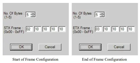
Configure the Transmit Control Bits (Mandatory)
Start of Transmission Bit: specifies the bit that initiates the transmission. The data is transmitted when the bit transitions from off to on. This bit is mandatory. Once set, it is up to the application to clear the bit.
Transmission Completion Bit: specifies the bit that is set when the data has been transmitted. The driver sets the bit, it is up to the application to clear the bit. This bit is optional.
Receive Tab
Configure the location of the received data (Mandatory)
Specify the starting register (address) of a series of registers. Use a D or @ register.Note: Registers in the HMC products are 16 bits wide. So, each register holds two ASCII characters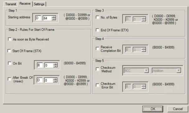
Configures when the driver begins accepting data (Mandatory)
Set rules for start of frame.
Select one of the following:
-As soon as Byte Received: reception starts with the receipt of the first byte.
-Start of Frame (STX): reception starts when the Start of Frame bytes are detected. When the box is checked, a dialog will be displayed, allowing the specification of up to five bytes.
-On Bit: data is received while the specified bit is set.
-After Break Of: reception starts after the interval (milliseconds) in the specified register has passed.
Configures when the driver stops accepting data (Mandatory)
Select one of the following:
-No of Bytes: reception stops when the number of bytes in the specified register have been received.
-End of Frame (ETX): reception stops when the End of Frame bytes are detected. When the box is checked, a dialog will be displayed, allowing the specification of up to five bytes.
Configures a bit that will be set when the data reception is complete (Optional)
Receive Completion Bit: specify a bit to be set. The bit will remain set until cleared by the applicationConfigure a checksum used to validate the packet (Optional)
The checksum included in the packet is checked against the checksum calculated by the selected method.
-Checksum Method: Select the method to use for calculating the checksum: CRC or a BCC. For the BCC, the available operations are Addition, 1’s Complement, 2’s Complement, and XOR (Exclusive OR).
-Checksum Error Bit: specify a bit to be set if the included and calculated checksums do not match. The bit will remain set until cleared by the application.
The driver expects the checksum as the last byte in the data packet.
Settings Tab
Set Response Timeout (Optional)
Specified register contains an interval in milliseconds. If no response is received within this interval, the HMC will resend the data until the Retry Count is reached. At that point, the Response Timeout Bit will be set. The bit will remain set until cleared by the application, or the transmission is triggered again. If Retry Count is enabled but set to 0, the Timeout bit will not be set.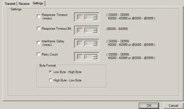
Set Response Timeout Bit (Optional)
Specify a bit to set if a timeout occurs.Set Interframe Delay (Optional)
Specified register contains an interval in milliseconds. This is the delay between when a response is received from a previous transmission, and the next transmission.Set Retry Count (Optional)
Specified register contains the number of total attempts at communication, after which the Response Timeout Bit will be set.Set Byte Format
Specify how the contents of each 16-bit register are sent and received.
Important! Click the Apply or Update button on the Node Information dialog after changing settings on the Driver Settings dialog to save the settings.
Sample Ladder
In most cases, ladder logic will have to be used to assemble the data to be transmitted, and parse the received data.
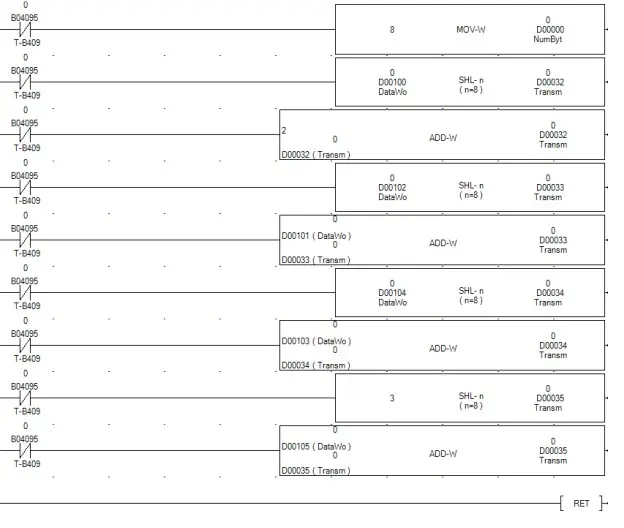
Example 1: This example shows how to assemble data to be transmitted. The data starts with an STX character, and ends with an ETX character. The data starts at register D32, and the number of bytes is specified by register D0.
First, the byte count (8) is moved into register D0. Next, eight bits from registersD100 are copied into the High byte of register D32, and the STX code (2) is added to register D32. This creates the required byte order of the first word of the transmit buffer. The process is repeated for all 8 data bytes, ending with the ETX code (3).
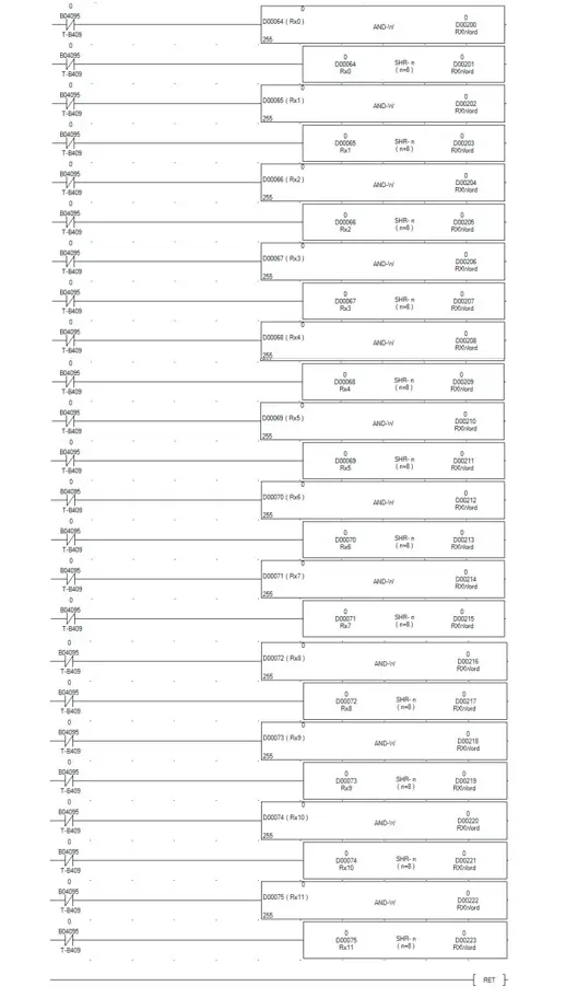
Example 2: This example shows how to decode received data. The data starts at register D64.
This logic copies the high and low bytes from each 16-bit receive buffer words to individual D registers, keeping the bytes in the proper order.
Wiring Diagram
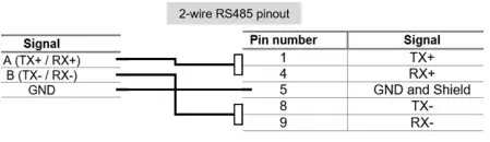
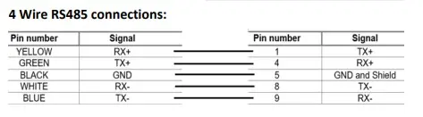
The Maple HMC connects directly to the communication port on the ASCII device. No specific cable is offered due to the variety of ASCII devices available.
WARNING: If your communications cable is not wired correctly, damage to the HMC or loss of communications can result.
Physical Port: 4.3″ Models
COM1: The 4.3″ models have 1 physical COM port that supports RS232 and RS485
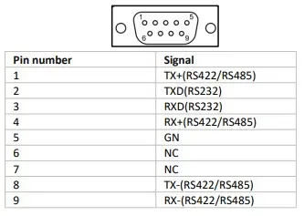
Physical Ports: 7.0″ Models
COM1: Terminal Block Port – RS232 / RS485
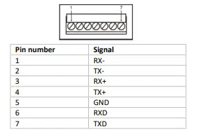
COM2: DE9 Female Port – RS232 / RS485
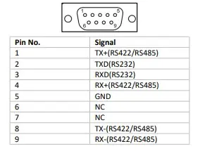
Physical Ports: 10.1″ Models
COM1 & COM2: The 10.1″ models have 2 physical COM ports that both supports RS232 and RS485
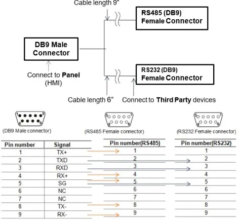
Y Type Cable (all models)
- Special “Y” cable for HMC unit (two communication levels on one port)
RS-485 – 2 Wire (all models)
RS-485 – 4 Wire (all models)
Ethernet Port (all models)
- Fully compliant with IEEE 802.3 / 802.3u standards.
- 10/100Mbps support.
- Connector used: Standard shielded RJ-45 female jack with in-built speed and link activity indication LEDs.
- Default IP Address: 192.168.0.254
- Default Subnet Activity Mask: 255.255.255.0
| Pin Number | Signal |
|---|---|
| 1 | TX+ |
| 2 | TX- |
| 3 | RX+ |
| 4 | NC |
| 5 | NC |
| 6 | RX- |
| 7 | NC |
| 8 | NC |