
Getting Started
Unpacking The Unit
Carefully unpack the PC2300B. Check all material in the container against the packing list. Maple Systems will not accept responsibility for shortages against the packing list unless notified within 30 days. The equipment and accessories were inspected and tested by Maple Systems before shipment.
Examine the equipment carefully; if any shipping damage is evident, notify the carrier immediately. Maple Systems is not responsible for claim negotiations with the carrier.
Save the shipping container and packing material in case the equipment needs to be stored, returned to Maple Systems, or transported for any reason.
| Packing List |
|---|
| PC2300B Series Heavy Industrial Panel PC |
| 3-Position Power connector (DC Power Input) |
| Mounting Clamp Kit |
CE Notice
This is a Class A product. In a domestic environment this product may cause radio interference in which case the user may be required to take adequate measures.
FCC Notice
This equipment has been tested and found to comply with the limits for a Class A digital device, pursuant to part 15 of the FCC Rules. These limits are designed to provide reasonable protection against harmful interference when the equipment is operated in a commercial environment. This equipment generates, uses, and can radiate radio frequency energy and, if not installed and used in accordance with the instruction manual, may cause harmful interference to radio communications. Operation of this equipment in a residential area is likely to cause harmful interference in which case the user will be required to correct the interference at his own expense.
You are cautioned that any change or modifications to the equipment not expressly approved by the party responsible for compliance could void your authority to operate such equipment.
Safety Precautions
Please observe the following precautions when installing the Industrial Box PC Series. Failure to comply with these restrictions could result in loss of life, serious personal injury, or equipment damage.

Warning: Disconnect this equipment from any power before cleaning. Do not use liquid or spray detergents for cleaning. Use a damp cloth.
Warning: Keep this equipment away from humidity.
Warning: Before applying power to the unit make sure the voltage of the power source is within the input voltage rating of the unit (12/24VDC). Operating the unit outside of this voltage specification can damage the unit and void your Warranty.
Warning: Never open the equipment and do not operate equipment with its heatsink cover removed- there are dangerous high voltages present inside. For safety reasons, the equipment should be opened only by a qualified service technician.
Warning: This equipment generates, uses and can radiate radio frequency energy and if not installed and used in accordance with the instruction manual, it may cause interference to radio communications.
This equipment has been tested and found to comply with the limits for a Class A computing device, pursuant to part 15 of the FCC Rules. These limits are designed to provide reasonable protection against harmful interference when the equipment is operated in a commercial environment.
Operation of this equipment in a residential area is likely to cause harmful interference in which case the user will be required to correct the interference at his own expense.
Warning: If any of the following situations arise, get the equipment checked by qualified service personnel.
- The power cord or plug is damaged.
- Liquid has penetrated into the equipment.
- The equipment has been exposed to moisture.
- The equipment does not work well, or you cannot get it to work according to this operations manual.
- The equipment has been dropped and damaged.
- The equipment has obvious signs of breakage.
Warning: Risk of explosion if the battery is replaced with an incorrect type. Batteries should be recycled where possible. Disposal of used batteries must be in accordance with local environmental regulations.
Warning: Do not leave this equipment in an uncontrolled environment where the storage temperature is below –20°C (-4°F) or above 80°C (176°F). It may damage the equipment.
Overview Of PC2300B Series
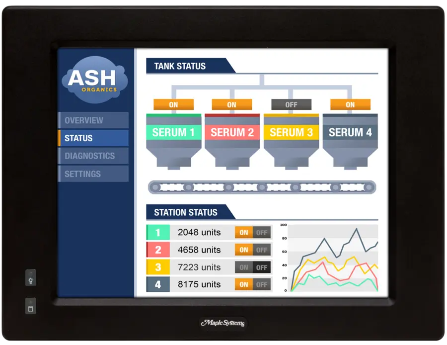
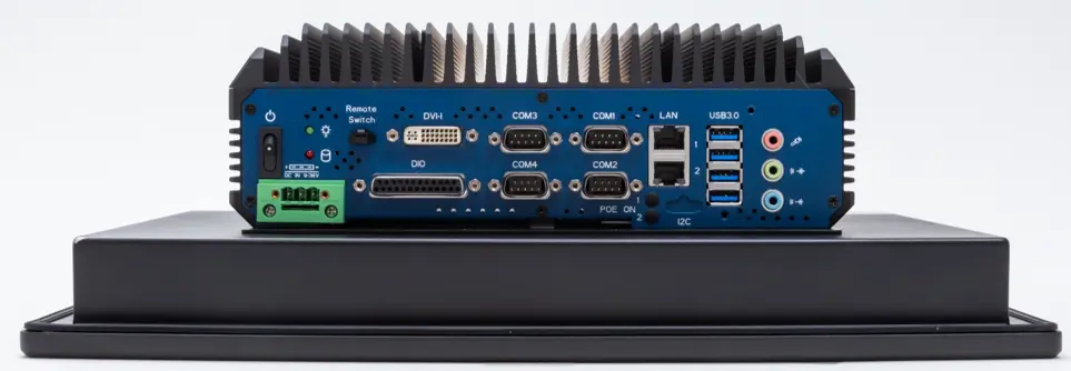
The PC2300B Series are fanless heavy industrial LCD touchscreen Panel PCs available in 15”, 17”, and 19” screen sizes. The PC2300B are powered by Intel® 7th Generation Core™ Processors, with up to 32GB of RAM.
Panel Mounting
How to Panel Mount the PC2300B Series
Follow the steps below to panel mount the PC2300B Series
Instructions: How to Panel Mount the PC2300B Series
Prepare Panel Cutout to Size
Cut out a section of the panel that corresponds to the cutout dimensions shown on the corresponding dimensional drawingPlace PC Through Panel Cutout
Place the PC2300B through the panel cutout so that the gasket surrounding the PC screen is flush against the panel surface.Install Side Mounting Brackets
Use the countersunk screws to mount the mounting bracket assembly to the side of the PC.
Install Clips to the bracket
Insert the mounting clips into the slots provided on the mounting brackets. There are two slots per bracket, designed to accommodate thicker panels. Use the slots closest to the front of the panel if possible.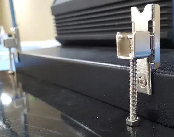
Tighten to Secure
Tighten the mounting clips in an even pattern until the PC is firmly held in place. The screws should be tight enough to slightly deform the gasket. Do not overtighten.Recommended torque: 5.1 in/lbs.
VESA Mounting
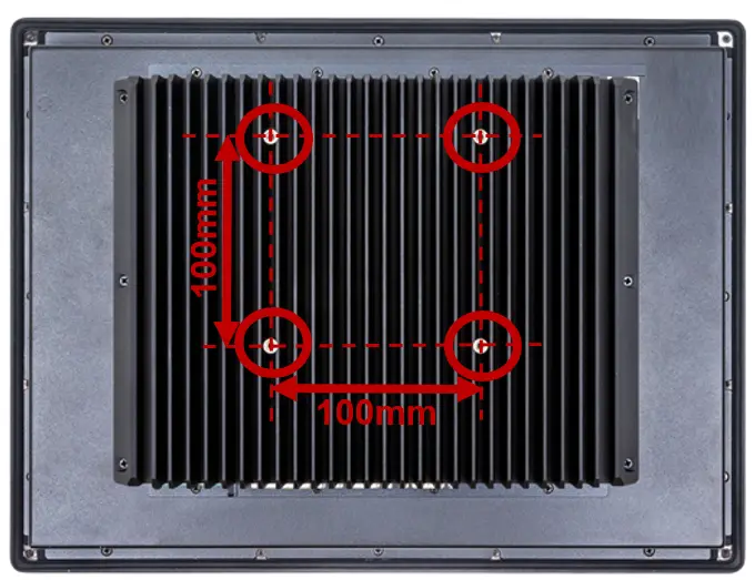
Select any compatible VESA mounting system and install according to the manufacturer’s instructions. The selected mounting system should be capable of supporting the net weight of the PC2300B as listed in the specifications above.
Mounting points on the rear of the unit are compatible with the Video Electronics Standards Association (VESA) Mounting Interface Standard (MIS) Part D. The mounting holes are arranged in a 100mm square pattern with M4 threads.
Touch Screen Calibration
The PC2300B is shipped with a factory touchscreen calibration and should work out of the box. A calibration tool is preloaded in the event that there is a problem with the factory calibration or the touchscreen needs recalibration. If the calibration of the touchscreen is inaccurate to the point where the touchscreen is not usable, a USB mouse can be used to access the calibration tool as described below.
Use the following steps to calibrate the touchscreen:
- Launch the eGalaxTouch utility by clicking on the desktop icon or through the start menu:
- All programs > eGalaxTouch > Configure Utility
- Select the tools tab and press the 4 Points Calibration button.
- Follow the instructions in the calibration window to complete the touchscreen calibration.
I/O Ports
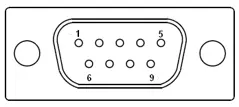
Serial COM Ports
Connector Type: 4ea DE9P Serial Ports.
| Pin # | COM1, COM2* | COM3, COM4 | ||
|---|---|---|---|---|
| (RS-232 Default) | (RS422) | (RS485) | (RS232) | |
| 1 | DCD | 422_TX- | 485- | DCD |
| 2 | RXD | 422_TX+ | 485+ | RXD |
| 3 | TXD | 422_RX+ | NC | TXD |
| 4 | DTR | 422_RX- | NC | DTR |
| 5 | GND | GND | GND | GND |
| 6 | DSR | NC | NC | DSR |
| 7 | RTS | NC | NC | RTS |
| 8 | CTS | NC | NC | CTS |
| 9 | RI | NC | NC | RI |
* Refer to the Setting COM Function section on page 20 to set the communication mode within the BIOS
Digital I/O Port
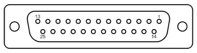
Connector Type: 1 x DB25S, digital I/O port
| PIN | ASSIGNMENT | PIN | ASSIGNMENT |
|---|---|---|---|
| 1 | DIN1 | 14 | DOUT1 |
| 2 | DIN2 | 15 | DOUT2 |
| 3 | DIN3 | 16 | DOUT3 |
| 4 | DIN4 | 17 | DOUT4 |
| 5 | DIN5 | 18 | DOUT5 |
| 6 | DIN6 | 19 | DOUT6 |
| 7 | DIN7 | 20 | DOUT7 |
| 8 | DIN8 | 21 | DOUT8 |
| 9 | NC | 22 | NC |
| 10 | NC | 23 | NC |
| 11 | NC | 24 | NC |
| 12 | NC | 25 | NC |
| 13 | NC | – | – |
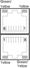
LAN Ports
Connector Type: 2 x Gigabit RJ45
LAN LED Indicator:
| Left side LED | Right side LED |
|---|---|
| Green Color On: 10/100 LAN Speed Indicator | Yellow Color Blinking: LAN Message Active |
| Yellow Color On: Giga LAN Speed Indicator | Off: No LAN Message |
| Off: No LAN switch/hub connected |
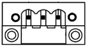
Power Input (9-36V DC)
Connector Type: 3-Pin Terminal Block

Audio Ports
Connector Type: 1 x Tri-Stacked 3.5mm audio jack
- MIC IN (Pink)
- LINE OUT (Green)
- LINE IN (Blue)
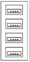
USB 3.0 Ports
Connector Type: 4 x USB 3.0 type A ports
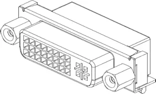
DVI-I Port
Connector Type: 1 x Digital Visual Interface – Integrated Connector
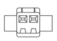
Remote Power Switch
Connector Type: 1 x 2-pin 2.5mm pitch wire-to-wire connector
Maple Systems offers a remote power switch cable P/N 7431-0127 (6’ cable with integrated power switch); contact your Maple Systems Sales Engineer for pricing, availability and other details.

BIOS Configuration Options
Introduction
The BIOS (Basic Input/Output System) installed in the ROM of your Panel PC supports Intel® processors. The BIOS provides critical low-level support for standard devices such as disk drives and serial ports. The BIOS also provides a Setup utility program that allows the user to specify system configuration and setting options.
Warning: Changing settings or configurations within the BIOS of your Panel PC can adversely impact the operation of your Panel PC if incorrectly performed.
Maple Systems provides the below instructions solely for the operations specified, and is not responsible for improper unit operation caused by changing settings or entries other than those explicitly listed below.
Entering Setup
When the system is powered on, the BIOS will enter the Power-On Self Test (POST) routines and the following message will appear on the screen:
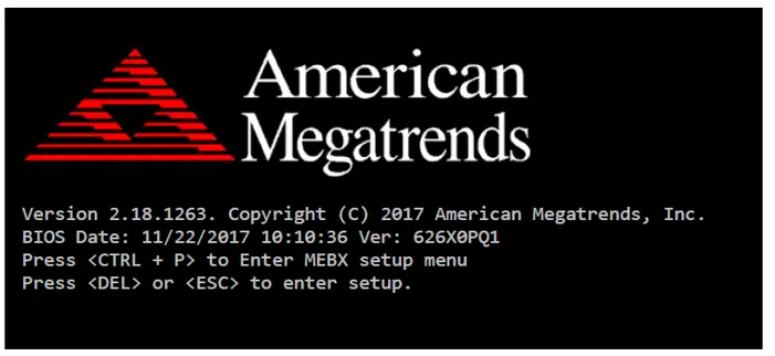
Example of initial POST screen. Your PC’s POST screen may appear different.
Press the <Delete> key immediately during the POST portion of your PC’s bootup sequence to enter the BIOS. The Main Menu containing the system summary information will appear.
Setting COM Function
The PC2300B COM1 and COM2 Serial Ports are configured by default as RS232, but can be configured for RS422 (4-wire) and RS485 (2-wire) operation if so desired. Port configuration is managed through the BIOS; see the below table for instructions on changing COM1 or COM2 port mode.
Note: COM1 and COM2 are the only ports that can be configured for RS422 or RS485 operation; COM3 and COM4 are exclusively configured for RS232 operation.
How to set COM Port Configuration
Follow these steps to set the COM Port configiration of your Panel PC.
Instructions: How to set COM Port Configuration
Enter the BIOS Setup Utility
Enter the BIOS Setup Utility by pressing [Delete] key during POST.
The Main menu containing the system summary information will appear.
Enter the Super IO Configuration menu
Navigate to the Advanced Tab and then enter the F1866 Super IO Configuration Menu.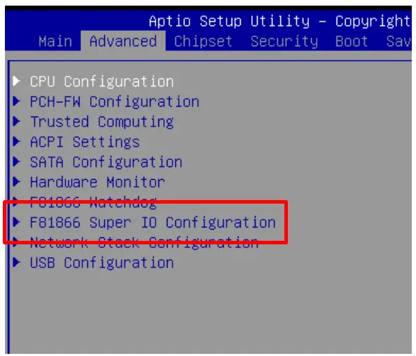
Select Serial Port 1/2 Configuration
Select the Serial Port 1 Configuration option to change the configuration of COM1.
Selecte the Serial Port 2 Configuration option to change the COM2 configuration.
Select the Mode
Select RS-232, RS-485, or RS-422 from the Device Mode Selection submenu.
Hit Enter to change the mode accordingly.
Save and Exit BIOS
Hit the F4 key to Save your changes and exit the BIOS.
Operating System Options
Windows® 10 IoT Enterprise LTSC
Windows® IoT Enterprise LTSC is a full Professional version of Windows® 10 available on all Industrial Box PC models. This powerful operating system delivers enterprise manageability and security to IoT solutions. Additionally, all of the features and functionality that customers expect to find on their desktop PC are available in this version. The Long-Term Servicing Channel (LTSC) version ensures long term stability that critical production systems require by updating only necessary operating system components, with significantly fewer update interruptions.
Included Apps with all Windows® OS options:
- Microsoft Edge Web Browser
- LibreOffice Suite (Compatible with the following document types:)
- MS Word
- MS Excel
- MS PowerPoint
- Adobe PDF
- Media Player
Windows® 11 IoT Enterprise LTSC
Windows® IoT Enterprise LTSC is a full Professional version of Windows® 11 available on all Industrial Box PC models. This powerful operating system delivers enterprise manageability and security to IoT solutions. Additionally, all of the features and functionality that customers expect to find on their desktop PC are available in this version. The Long-Term Servicing Channel (LTSC) version ensures long term stability that critical production systems require by updating only necessary operating system components, with significantly fewer update interruptions.
Included Apps with all Windows® OS options:
- Microsoft Edge Web Browser
- LibreOffice Suite (Compatible with the following document types:)
- MS Word
- MS Excel
- MS PowerPoint
- Adobe PDF
- Media Player
Windows® 11 Professional
Windows® 11 Professional is a full professional version of Windows®. All the features and functionality that customers expect to find on their desktop PC are available in this version. This powerful operating system lifetime security updates for the duration of Microsoft’s support timeline of the OS. These versions are operationally identical to the Consumer operating System versions of Windows®, and as such they provide regular feature and functionality updates on a more frequent schedule than Enterprise editions of the same OS.