
Getting Started
Unpacking the Unit
Carefully unpack the Industrial Panel PC. Check all material in the container against the packing list. Maple Systems will not accept responsibility for shortages against the packing list unless notified within 30 days. The equipment and accessories were inspected and tested by Maple Systems before shipment.
Examine the equipment carefully; if any shipping damage is evident, notify the carrier immediately. Maple Systems is not responsible for claim negotiations with the carrier.
Save the shipping container and packing material in case the equipment needs to be stored, returned to Maple Systems, or transported for any reason.
| Packing List |
|---|
| PC1000 Series Panel PC unit |
| Power Cable (for use with existing DC Power Supply) |
| M4x5mm VESA Mounting Screws (Set of 4) |
| Mounting Clips (Quantity Dependent on PC screen size) |
Safety Precautions
Please observe the following precautions when installing the Industrial Box PC Series. Failure to comply with these restrictions could result in loss of life, serious personal injury, or equipment damage.

Warning: Disconnect this equipment from any power before cleaning. Do not use liquid or spray detergents for cleaning. Use a damp cloth.
Warning: Keep this equipment away from humidity.
Warning: Before applying power to the unit make sure the voltage of the power source is within the input voltage rating of the unit (+9~36VDC). Operating the unit outside of this voltage specification can damage the unit and void your Warranty.
Warning: Never open the equipment and do not operate equipment with its heatsink cover removed- there are dangerous high voltages present inside. For safety reasons, the equipment should be opened only by a qualified service technician.
Warning: This equipment generates, uses and can radiate radio frequency energy and if not installed and used in accordance with the instruction manual, it may cause interference to radio communications. This equipment has been tested and found to comply with the limits for a Class A computing device, pursuant to part 15 of the FCC Rules. These limits are designed to provide reasonable protection against harmful interference when the equipment is operated in a commercial environment. Operation of this equipment in a residential area is likely to cause harmful interference in which case the user will be required to correct the interference at his own expense.
Warning: If any of the following situations arise, get the equipment checked by qualified service personnel.
- The power cord or plug is damaged.
- Liquid has penetrated into the equipment.
- The equipment has been exposed to moisture.
- The equipment does not work well, or you cannot get it to work according to this operations manual.
- The equipment has been dropped and damaged.
- The equipment has obvious signs of breakage.
Warning: Risk of explosion if the battery is replaced with an incorrect type. Batteries should be recycled where possible. Disposal of used batteries must be in accordance with local environmental regulations.
Warning: Do not leave this equipment in an uncontrolled environment where the storage temperature is below -40°C (-40°F) or above 85°C (185°F). It may damage the equipment.
Overview
PC1000 Series Panel PC units are industrial, heavy duty fanless PCs available in four main categories: PC1200, PC1300, PC1400, and PC1500 Series. Display sizes range from 10.4 ~ 27”, with select displays offering a high-brightness (1000 nits) option. High brightness displays are ideal for use in environments where there is a larger than normal amount of ambient light, allowing for the user to maintain readability of the PC display.
All PC1000 Panel PCs feature Projected Capacitive Touch Screens, which allow for a more natural, intuitive user touch experience compared to traditional analog-resistive touch screen terminals. All PC1000 units feature dual Gigabit Ethernet Ports, allowing for simultaneous connection to multiple networks. Each PC1000 unit comes with Microsoft Windows® 10 IOT LTSC 64-bit pre-installed.
PC1000 Series Panel PCs are NEMA4 rated and carry a rugged IP65 certification (when panel mounted). PC1000 Series units can be factory equipped with Wi-Fi, enabling access to existing 802.11 b/g/n wireless networks.
For detailed specifications for PC1200, PC1300, PC1400, and PC1500 Series models, including CAD drawings, please see the datasheet posted on the unit’s product page on maplesystems.com.
PC1200 Series Models
The PC1200 Series is powered by the Intel® Pentium™ N4200 1.1GHz quad-core processor. Memory options include 4GB or 8GB of DDR3L RAM. Solid State Drive options include sizes from 64GB to 1TB (Other options may be available; contact Maple Systems for details).
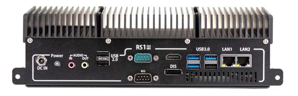
PC1200 Series units have 4 x USB 3.0 ports, 2 x RJ45 ports, 2 x USB 2.0 ports, 1 x HDMI, 1 x Line-out, 1 x Mic-in, and 3 x DE-9P serial ports.

PC1300 Series Models
The PC1300 Series units boast a 7th Generation Intel® Kaby Lake Core™ i-Series Processors (i3-7100U – 2.4GHz, i5-7300U – 2.6GHZ, i7-7600U – 2.8GHz) with up to 32GB of DDR4 RAM. Solid State Drive options include sizes from 64GB to 1TB (Other options may be available; contact Maple Systems for details).
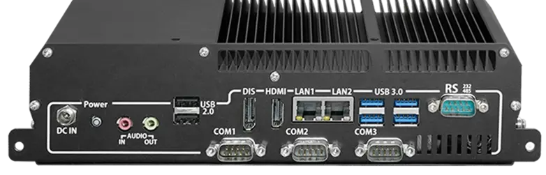
PC1300 Series units have 4 x USB 3.0 ports, 2 x RJ45 ports, 2 x USB 2.0 ports, 1 x HDMI, 1 x DisplayPort, 1 x Line-Out, 1 x Mic-In, and 4 x DE-9P serial ports.
PC1400 Series Models
The PC1400 Series are equipped with an Intel® Alder Lake-N Core™ N97 Quad Core Processor running at 3.60 GHz with up to 32GB of SO-DIMM DDR5 RAM. Solid State Drive options include sizes from 128GB to 2TB (Other options may be available; contact Maple Systems for details).
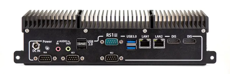
PC1400 units have 2 x USB 3.0 ports, 2 x RJ45 ports, 2 x USB 2.0 ports, 2 x DisplayPort, 1 x Line-Out, 1 x Mic-In, and 4 x DE-9P serial ports.
PC1500 Series Models
The PC1500 Series are equipped with an Intel® Core™ Ultra 5 Processor (Meteor Lake) 12-Core CPU (2P+8E+2LP-E). Running at a P-Core base frequency of 1.3GHz with max frequency of 4.3GHz for 125U series or Intel® Core™ Ultra 7 Processor (Meteor Lake) P-Core base frequency of 1.7GHz with max frequency of 4.8GHz for 155U series. Accompanied with up to 64GB of SO-DIMM DDR5 RAM. Solid State Drive options include sizes from 128GB to 2TB (Other options may be available; contact Maple Systems for details).
PC1500 Series units have 4 x USB 3.0 ports, 2 x RJ45 ports, 2 x USB 2.0 ports, 1 x HDMI, 1 x DisplayPort, 1 x Line-Out, 1 x Mic-In, and 2 x DE-9P serial ports.
Mounting Options
Panel Mounting
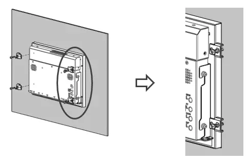
PC1000 units can be panel mounted using the mounting holes located on the rear of the unit. Use the included clamps to fasten the unit to the panel, cut out to the proper dimensions on the datasheet corresponding to your display size. Tighten the bolts no more than 5.1 in./lbs. to ensure an adequate seal. Over torquing the bolts may possibly negate NEMA or IP65 rating, or cause damage to the unit or panel.
Maple Systems is not responsible for damage to unit, mounting surface or any other components caused by improper mounting.
VESA Mounting
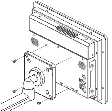
In addition to panel mounting, the PC1000 Series Panel PCs offer VESA 100 mounting as an option. VESA 100 x 100 mm threaded inserts are located on the rear of the unit. Use M4 threaded mounting screws to attach your VESA mounting bracket (not provided by Maple Systems) to the Panel PC.
Your PC comes with M4x5mm mounting screws, but your VESA bracket may require screws of a different length. Use VESA mounting brackets sufficient for the application. Maple Systems is not responsible for damage to unit, mounting surface or any other components caused by improper mounting.
I/O Ports
HDMI®
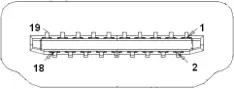
HDMI Connector available on PC1200, PC1300 and PC1500 Series models
Connector Type: High Definition Multimedia Interface® Socket
DisplayPort
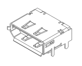
DisplayPort Connector available on PC1300, PC1400 and PC1500 Series models
Connector Type: DisplayPort Interface Connector Socket
USB 3.0
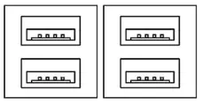
All PC1000 Series models have 4 x USB 3.0 Type A Host Ports
Note: USB 3.0 allows data transfers up to 5Gb/s, full-speed, and low-speed signaling. The total current output limit is 1.8A per Stacked Hub (0.9A per individual port)
USB 2.0
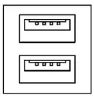
All PC1000 Series models have 2 x USB 2.0 Type A Host Ports
Note: USB 2.0 allows data transfers up to 480Mb/s, full-speed, and low-speed signaling. The total current output limit is 1.0A per Stacked Hub (0.5A per individual port)
LAN1, LAN2
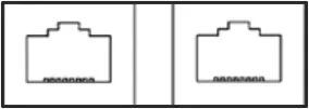
Connector Type: Standard 10/100/1000M RJ-45 Ethernet ports (PC1200, PC1300, PC1400)
Connector Type: Standard 10/100/1000/2500M RJ-45 Ethernet ports (PC1500)

Audio-Out
Connector Type: 3.5mm audio jack output

Audio-In
Connector Type: 3.5mm audio jack input
COM1-COM4:
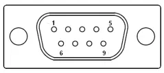
(COM4 only on PC1300 and PC1400 Series)
Connector Type: DE9P Male Serial Ports
| Pin # | COM1* | COM2 | COM3 | COM4** | ||
|---|---|---|---|---|---|---|
| (RS-232 Default) | (RS422) | (RS485) | (RS232) | (RS232) | (RS232) | |
| 1 | DCD | 422_TX- | 485- | DCD | DCD | DCD |
| 2 | RXD | 422_TX+ | 485+ | RXD | RXD | RXD |
| 3 | TXD | 422_RX+ | NC | TXD | TXD | TXD |
| 4 | DTR | 422_RX- | NC | DTR | DTR | DTR |
| 5 | GND | GND | GND | GND | GND | GND |
| 6 | DSR | NC | NC | DSR | DSR | DSR |
| 7 | RTS | NC | NC | RTS | RTS | RTS |
| 8 | CTS | NC | NC | CTS | CTS | CTS |
| 9 | RI | NC | NC | RI | RI | RI |
| * Refer to “Setting COM1 Function” to set the communication mode. | ** COM4 only on PC1300 and PC1400 Series | |||||
BIOS Configuration Options
The BIOS (Basic Input/Output System) installed in the ROM of your Panel PC supports Intel® processors. The BIOS provides critical low-level support for standard devices such as disk drives and serial ports. The BIOS also provides a Setup utility program that allows the user to specify system configuration and setting options.
Warning: Changing settings or configurations within the BIOS of your Panel PC can adversely impact the operation of your Panel PC if incorrectly performed.
Maple Systems provides the below instructions solely for the operations specified, and is not responsible for improper unit operation caused by changing settings or entries other than those explicitly listed below.
To enter the BIOS of your Panel PC, ensure a USB keyboard is connected to your PC and apply power. Your panel PC is automatically configured to boot up when power is applied.
Press the <Delete> key immediately during the POST (Power On Self-Test) portion of your PC’s bootup sequence to enter the BIOS. The Main Menu containing the system summary information will appear.
Setting COM1 Function
The PC1000 COM1 Serial Port is configured by default as RS232, but can be configured for RS422 (4-wire) or RS485 (2-wire) operation if so desired. COM1 port configuration is managed through the BIOS; see below for instructions on changing COM1 port mode.
Note: COM1 is the only port that can be configured for RS422 or RS485 operation; all other Serial Ports are exclusively configured for RS232 operation.
How to change Serial Port COM Mode
Follow these steps to change COM2 and COM3 mode between RS232 and RS422 or RS485 if desired.
Instructions: How to change Serial Port COM Mode
Enter BIOS menu
Boot the PC up and press the [DEL] key to enter the BIOS Main Menu.Go to Advanced submenu
At the BIOS Main Menu, press the right arrow key for the Advanced submenu.Open the Super IO Configuration Menu
Select the F81846 Super IO Configuration menu and press the Enter key.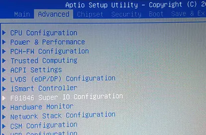
Select the Serial Port 1 Configuration submenu
Select the Serial Port 1 Configuration menu option and press the Enter key.Serial Port 1 is the only configurable port.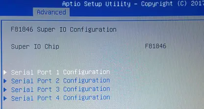
Select Serial Port 1 Configuration Mode
Select the F81846 Serial Port 1 Mode Select menu option and press the Enter key.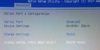
Choose COM Mode
Select the [RS232], [RS485], or [RS422] option, depending on your desired port configuration and press the Enter key.The COM mode is RS-232 by default.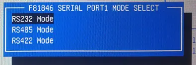
Save and Exit BIOS
Press the F4 key to save and exit.Make sure to SAVE changes before exiting the BIOS. The F4 key brings up the save option.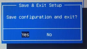
Automatically Startup When Power Is Applied (PC1300, PC1400, PC1500)
When a Panel PC unit is panel-mounted, the power button becomes inaccessible. There is an option in the PC1300, PC1400, and PC1500 Series BIOS that allows for the unit to be powered up when DC power is applied. This option is ENABLED by default – if this is the behavior you want you don’t have to do anything.
How to configure the BIOS to enable or disable Automatic Startup
Follow these steps to enable the PC1000 unit to enable or disable the automatic startup when power is applied.
Instructions: How to configure the BIOS to enable or disable Automatic Startup
Enter BIOS menu
Boot the PC up and press the [DEL] or [F2] key to enter the BIOS Main Menu.Go to Advanced submenu
At the BIOS Main Menu, press the right arrow key for the Advanced submenu.Select iSmart Controller menu
Select the iSmart Controller menu and press the Enter key.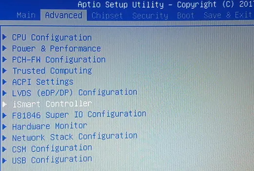
Power-On After System Failure Option
Select the Power-On After Power failure menu option and press the Enter key.In this example, the option is currently showing disabled; we are enabling it.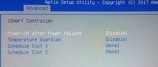
Enable or Disable the Option
Select [ENABLE] with the arrow keys and press the Enter key to enable.
Select [DISABLE] with the arrow keys and press the Enter key to disable.
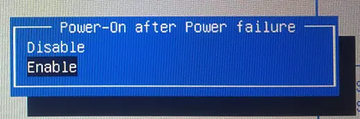
Save and Exit BIOS
Press the F4 key to save and exit.Make sure to SAVE changes before exiting the BIOS. The F4 key brings up the save option.
Operating System Options
The PC1000 Series Panel PCs can be purchased with the following operating systems pre-installed:
- Windows® 10 IoT Enterprise LTSC
- Windows® 10 IoT Enterprise Embedded LTSC
- Windows® 11 IoT Enterprise LTSC (PC1300, PC1400, PC1500 Series)
- Windows® 11 IoT Enterprise Embedded LTSC (PC1300, PC1400, PC1500 Series)
- Windows® 11 Professional (PC1300, PC1400, PC1500 Series)
- Ubuntu Linux Desktop LTS
Windows® 10 IoT Enterprise LTSC / Windows® 11 IoT Enterprise LTSC (PC1300, PC1400, PC1500)
Windows® IoT Enterprise is a full enterprise version of Windows® 10 / Windows® 11 available on all Industrial Panel PC models. This powerful operating system delivers enterprise manageability and security to IoT solutions. Additionally, all of the features and functionality that customers expect to find on their desktop PC are available in this version. The Long Term Servicing Channel (LTSC – Windows® 10 and Windows® 11) version ensures long term stability that critical production systems require by updating only necessary operating system components, with significantly fewer update interruptions.
Included Apps with all Windows® OS options:
- Microsoft Edge Web Browser
- LibreOffice Suite (Compatible with the following document types:)
- MS Word
- MS Excel
- MS PowerPoint
- Adobe PDF
- Media Player
Windows® 11 Professional (PC1300, PC1400, PC1500)
Windows® 11 Professional is a full professional version of Windows®. All the features and functionality that customers expect to find on their desktop PC are available in this version. This powerful operating system lifetime security updates for the duration of Microsoft’s support timeline of the OS. These versions are operationally identical to the Consumer operating System versions of Windows®, and as such they provide regular feature and functionality updates on a more frequent schedule than Enterprise editions of the same OS.
Ubuntu Linux Desktop LTS
This powerful Operating System delivers enterprise manageability and security across a wide range of industries. Additionally, most features and functionality that customers expect to find on their desktop PCs are available in this Open-Source Operating System. The Long-Term Support (LTS) version ensures long-term stability with five years of free security and maintenance updates.
AVEVA Edge
All of the PC1000 Series PCs are compatible with most Windows® based SCADA Software, including our AVEVA Edge. Visit maplesystems.com/software/aveva-edge for more information.