Introduction
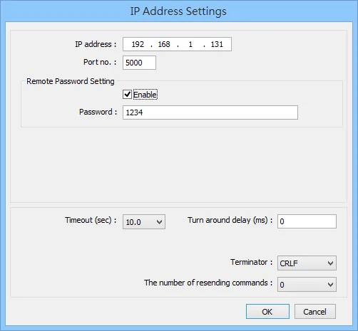
All Maple Systems HMIs programmed with EBPro (EasyBuilder Pro), including every cMT X Series and cMT Series model, are compatible with Epson Robot Controller. Configure your Controller and HMI/cMT with the following parameters to establish reliable communication.
Supported Series: Epson Robot Controller
Website: https://global.epson.com/
HMI Setting
| Parameters | Recommended | Options | Notes |
|---|---|---|---|
| PLC type | Epson Robot Controller | ||
| PLC I/F | Ethernet | ||
| Port no. | 5000 | *Note | |
| Terminator | CRLF | CRLF / CR / LF |
NOTE: Make sure that the communication port does not conflict with other devices.
Device Address
NOTE: The address and range of different controller models may be different.
| Bit/Word | Device type | Format | Range | Memo |
|---|---|---|---|---|
| B | LOGIN | D | 0 | Set 1 (Initialization) |
| B | LOGOUT | D | 0 | |
| B | STOP | D | 0 | |
| B | PAUSE | D | 0 | |
| B | CONTINUE | D | 0 | |
| B | RESET | D | 0 | |
| B | MOTOR | DD | 1 ~ 16 | Motor on / off No.1 ~ 16 Robot |
| B | IN_BIT | DDDDD | 0 ~ 65535 | |
| B | OUT_BIT | DDDDD | 0 ~ 65535 | |
| B | MEMIO_BIT | DDDDD | 0 ~ 65535 | |
| B | STATUS_TEST | D | 0 | |
| B | STATUS_TEACH | D | 0 | |
| B | STATUS_AUTO | D | 0 | |
| B | STATUS_WARNING | D | 0 | |
| B | STATUS_SERROR | D | 0 | |
| B | STATUS_SAFEGUARD | D | 0 | |
| B | STATUS_ESTOP | D | 0 | |
| B | STATUS_ERROR | D | 0 | |
| B | STATUS_PAUSE | D | 0 | |
| B | STATUS_RUNNING | D | 0 | |
| B | STATUS_READY | D | 0 | |
| B | ABORT | D | 0 | |
| B | STAT_BIT | DDD | 0 ~ 331 | *Note2 |
| B | RBTINF_BIT | DDD | 0 ~ 531 | *Note3 |
| B | POWER | D | 0 | On: High / Off: Low |
| B | CTRLINF_BIT | DDDD | 0 ~ 1031 | *Note4 |
| B | ATCLR | D | 1 ~ 9 | Clear and initializes the average torque |
| B | PTCLR | D | 1 ~ 9 | Clear and initializes the peak torque |
| B | IO_MAP_BIT | D | 0 | *Note9 |
| B | CONSOLE | D | 0 | *Note11 |
| B | +X_TOOL | D | 0 | |
| B | -X_TOOL | D | 0 | |
| B | +Y_TOOL | D | 0 | |
| B | -Y_TOOL | D | 0 | |
| B | +Z_TOOL | D | 0 | |
| B | -Z_TOOL | D | 0 | |
| B | +U_TOOL | D | 0 | |
| B | -U_TOOL | D | 0 | |
| B | +V_TOOL | D | 0 | |
| B | -V_TOOL | D | 0 | |
| B | +W_TOOL | D | 0 | |
| B | -W_TOOL | D | 0 | |
| B | +X_WORLD | D | 0 | |
| B | -X_WORLD | D | 0 | |
| B | +Y_WORLD | D | 0 | |
| B | -Y_WORLD | D | 0 | |
| B | +Z_WORLD | D | 0 | |
| B | -Z_WORLD | D | 0 | |
| B | +U_WORLD | D | 0 | |
| B | -U_WORLD | D | 0 | |
| B | +V_WORLD | D | 0 | |
| B | -V_WORLD | D | 0 | |
| B | +W_WORLD | D | 0 | |
| B | -W_WORLD | D | 0 | |
| B | +J1 | D | 0 | |
| B | -J1 | D | 0 | |
| B | +J2 | D | 0 | |
| B | -J2 | D | 0 | |
| B | +J3 | D | 0 | |
| B | -J3 | D | 0 | |
| B | +J4 | D | 0 | |
| B | -J4 | D | 0 | |
| B | +J5 | D | 0 | |
| B | -J5 | D | 0 | |
| B | +J6 | D | 0 | |
| B | -J6 | D | 0 | |
| B | HAND_POS | D | 0 | |
| B | ELBOW | D | 0 | |
| B | WRIST | D | 0 | |
| W | LOGINPASS | D | 0 ~ 8 | ASCII *Note1 |
| W | START | D | 0 | |
| W | CURROBOT | D | 0 | Read: Display Robot / Write: Select Robot |
| W | HOME | D | 0 | Target Robot |
| W | IN_WORD | DDDD | 0 ~ 4095 | |
| W | OUT_WORD | DDDD | 0 ~ 4095 | |
| W | MEMIO_WORD | DDDD | 0 ~ 4095 | |
| W | STATUS_ERROR_CODE | D | 0 | |
| DW | STAT | D | 0 ~ 3 | *Note2 |
| DW | RBTINF | D | 0 ~ 5 | *Note3 |
| W | IO_LABEL | DDDDDDDDD | 0 ~ | ASCII *Note4 |
| W | SYSERR | D | 0 ~ 1 | 0: Error code / 1: Warning code |
| DW | CTRLINF | DD | 0 ~ 10 | *Note4 |
| DW (float) | RBTW | D | 1 ~ 9 | X,Y,Z,U,V,W,R,S,T |
| DW (float) | RBTJ | D | 1 ~ 9 | 1,2,3,4,5,6,7,S,T |
| W | RBTP | D | 1 ~ 9 | 1,2,3,4,5,6,7,S,T |
| W | SPEED | D | 0 ~ 2 | *Note5 |
| W | ACCEL | D | 0 ~ 5 | *Note6 |
| DW (float) | REALTRQ | D | 1 ~ 9 | Joint Number |
| DW (float) | ATRQ | D | 1 ~ 9 | Joint Number |
| DW (float) | PTRQ | D | 1 ~ 9 | Joint Number |
| DW (float) | QLRATE | D | 1 ~ 9 | Joint Number |
| W | CNT_NAME | DD | 0 ~ 15 | ASCII |
| W | CNT_NO | DD | 0 ~ 15 | ASCII |
| W | PRJ_NAME | DD | 0 ~ 15 | ASCII |
| W | MAIN_LIST | DD | 0 ~ 65 | *Note7 |
| W | GET_TASK_INF | DD | 0 ~ 59 | *Note8 |
| W | TASK_FUN_NAME | DDDD | 100 ~ 5999 | AABB — AA: Existing task no. / BB: Fill 00 (ASCII) |
| W | TASK_STATUS | DDDD | 100 ~ 5999 | |
| W | TASK_TYPE | DDDD | 100 ~ 5999 | |
| W | TASK_START_TIME | DDDD | 100 ~ 5999 | |
| DW | TASK_EXE_LINE | DD | 1 ~ 59 | Existing task no. |
| W | GETMAIN | D | 0 | |
| W | IO_MAP | D | 0 | *Note9 |
| W | GETIOSTR | HH | 0 ~ A8 | *Note10 |
| W | GET_ERR_HIS_NUM | D | 0 | Number of history |
| W | ERR_HIS_CODE | DD | 1 ~ 49 | Error history no. |
| W | ERR_HIS_FUN_NAME | DDDD | 100 ~ 4999 | AABB — AA: Error history no. / BB: Fill 00 (ASCII) |
| DW | ERR_HIS_LINE | DD | 1 ~ 49 | Error history no. |
| W | ERR_HIS_INT_CODE | DD | 1 ~ 49 | Error history no. |
| W | ERR_HIS_TIME | DDDD | 100 ~ 4999 | AABB — AA: Error history no. / BB: Fill 00 (ASCII) |
| W | ERR_HIS_ROBOT_NO | DD | 1 ~ 49 | Error history no. |
| W | ERR_HIS_AXIS_NO | DD | 1 ~ 49 | Error history no. |
| W | ERR_HIS_TASK_NO | DD | 1 ~ 49 | Error history no. |
| W | ERR_HIS_INFO1 | DDDD | 100 ~ 4999 | AABB — AA: Error history no. / BB: Fill 00 (ASCII) |
| W | ERR_HIS_INFO2 | DDDD | 100 ~ 4999 | AABB — AA: Error history no. / BB: Fill 00 (ASCII) |
| W | ERR_HIS_MESSAGE | DDDD | 100 ~ 4999 | AABB — AA: Error history no. / BB: Fill 00 (ASCII) |
| W | ERR_MESSAGE | DDDD | 0 ~ 9999 | ASCII |
| W | PFILELIST | DDDDDD | 10000 ~ 169999 | AABB — AA: Robot no. / BB: File index / CC: Fill 00 (ASCII) |
| W | LOADPFILE | DDDDD | 100 ~ 16099 | AABB — AA: Robot no / BB: Fill 00 (ASCII) |
| W | GETPINF | DD | 0 ~ 54 | 0: Write 1 to read / 1: Robot no. / 2: Stat point no. / 3: End point no. / 4: number of points / 5~54: point |
| W | PINF_POINT_NO | DD | 0 ~ 49 | Point |
| DW (float) | PINF_X_COORDINATE | DD | 0 ~ 49 | Point |
| DW (float) | PINF_Y_COORDINATE | DD | 0 ~ 49 | Point |
| DW (float) | PINF_Z_COORDINATE | DD | 0 ~ 49 | Point |
| DW (float) | PINF_U_COORDINATE | DD | 0 ~ 49 | Point |
| DW (float) | PINF_V_COORDINATE | DD | 0 ~ 49 | Point |
| DW (float) | PINF_W_COORDINATE | DD | 0 ~ 49 | Point |
| DW (float) | PINF_R_COORDINATE | DD | 0 ~ 49 | Point |
| DW (float) | PINF_S_COORDINATE | DD | 0 ~ 49 | Point |
| DW (float) | PINF_T_COORDINATE | DD | 0 ~ 49 | Point |
| W | PINF_HAND | DD | 0 ~ 49 | 0: Error / 1: Lefty / 2: Righty |
| W | PINF_ELBOW | DD | 0 ~ 49 | 0: Error / 1: Below / 2: Ablow |
| W | PINF_WRIST | DD | 0 ~ 49 | 0: Error / 1: Flip / 2: No. flip |
| W | PINF_J4FLAG | DD | 0 ~ 49 | |
| W | PINF_J6FLAG | DD | 0 ~ 49 | |
| W | PINF_J1FLAG | DD | 0 ~ 49 | |
| W | PINF_J2FLAG | DD | 0 ~ 49 | |
| W | PINF_J1ANGLE | DD | 0 ~ 49 | |
| W | RBTINF_NUM | D | 0 | 1 ~ 16 |
| W | RBTINF_TYPE | DD | 1 ~ 16 | |
| W | RBTINF_MODEL_NAME | DDDD | 100 ~ 1699 | AA: 1~16 / BB: Fill 00 (ASCII) |
| DW | ENET_TOTAL_TIME | D | 0 | |
| DW | ENET_POWER_ON_TIME | D | 0 | |
| DW | EXTTIME_MOTOR_ON | DD | 1 ~ 16 | |
| DW | EXTTIME_MOTOR_ON_NUM | DD | 1 ~ 16 | |
| DW (float) | X_STEP_DISTANCE | D | 0 | Step distance control |
| DW (float) | Y_STEP_DISTANCE | D | 0 | Step distance control |
| DW (float) | Z_STEP_DISTANCE | D | 0 | Step distance control |
| DW (float) | U_STEP_DISTANCE | D | 0 | Step distance control |
| DW (float) | V_STEP_DISTANCE | D | 0 | Step distance control |
| DW (float) | W_STEP_DISTANCE | D | 0 | Step distance control |
| DW (float) | J1_STEP_DISTANCE | D | 0 | Step distance control |
| DW (float) | J2_STEP_DISTANCE | D | 0 | Step distance control |
| DW (float) | J3_STEP_DISTANCE | D | 0 | Step distance control |
| DW (float) | J4_STEP_DISTANCE | D | 0 | Step distance control |
| DW (float) | J5_STEP_DISTANCE | D | 0 | Step distance control |
| DW (float) | J6_STEP_DISTANCE | D | 0 | Step distance control |
| W | GO | D | 0 | |
| W | JUMP | D | 0 | |
| W | JUMP3 | D | 0 ~ 3 | 0: write1 to execute / 1~3: point |
| W | JUMP3CP | D | 0 ~ 3 | 0: write1 to execute / 1~3: point |
| W | MOVE | D | 0 | |
| W | ARC | D | 0 ~ 2 | 0: write1 to execute / 1~2: point |
| W | ARC3 | D | 0 ~ 2 | 0: write1 to execute / 1~2: point |
| W | T_POINT | D | 0 ~ 1 | |
| W | SELECT_POINT_FILE | DD | 1 ~ 16 | Write only |
| W | J1FLAG | D | 0 | |
| W | J4FLAG | D | 0 | |
| W | J6FLAG | D | 0 | |
| W | PINF_LOCAL | DDD | 0 ~ 999 | 0~15, 256~272 (CNV(1)~CNV(16)) |
| W | PINF_LABEL | DDDDD | 0 ~ 99999 | Use ASCII Object — AA: 0~999 / BB: Fill 00 (ASCII) |
Notes
Note 1
When [Remote Password Setting] is checked, the set password will be automatically filled in to this address.
Note 2: STAT_BIT / STAT Address Map
| Address | Bit | Description |
|---|---|---|
| 0 | 0–15 | Task 1–16 are executing (Xqt) or Halt condition |
| 0 | 16 | Task is executing |
| 0 | 17 | Pause condition |
| 0 | 18 | Error condition |
| 0 | 19 | TEACH mode |
| 0 | 20 | Emergency stop condition |
| 0 | 21 | Low power mode (Power Low) |
| 0 | 22 | Safety door input is open |
| 0 | 23 | Enable switch is open |
| 1 | 0 | Conditional approval of Jump…Sense statement at history of target coordinates over the suspension. |
| 1 | 1 | Conditional approval of Go/Jump/Move…Till statement at history of operating suspend. |
| 1 | 2 | Undefined |
| 1 | 3 | Conditional approval of Trap statement at history of operating suspend |
| 1 | 4 | Motor On condition |
| 1 | 5 | Home position at currently |
| 1 | 6 | Low power condition |
| 1 | 7 | Undefined |
| 1 | 8 | Joint 4 motor is on |
| 1 | 9 | Joint 3 motor is on |
| 1 | 10 | Joint 2 motor is on |
| 1 | 11 | Joint 1 motor is on |
| 1 | 12 | Joint 6 motor is on |
| 1 | 13 | Joint 5 motor is on |
| 1 | 14 | Joint T motor is on |
| 1 | 15 | Joint S motor is on |
| 1 | 16 | Joint 7 motor is on |
| 2 | 0–15 | Task 17–32 are executing (Xqt) or Halt condition |
Note 3: RBTINF_BIT / RBTINF Address Map
| Address | Bit | Description |
|---|---|---|
| 0 | 0 | Undefined |
| 0 | 1 | Resettable error occur |
| 0 | 2 | Unresettable error occur |
| 0 | 3 | Motor ON |
| 0 | 4 | Power High |
| 0 | 8 | Robot is Halt condition |
| 0 | 9 | Robot is not Halt condition (operating or quick pausing) |
| 0 | 10 | Robot is stop at pausing or safety door |
| 0 | 14 | Meet TILL condition, after operation command |
| 0 | 15 | Meet SENSE condition, after operation command |
| 1 | 0 | In the follow-up operation (In the conveyor tracking) |
| 1 | 1 | Wait for return action (WaitRecover condition) |
| 1 | 2 | Return action is executing |
| 2 | 0 | Robot is home position |
| 3 | 0 | Joint 1 servo is on |
| 3 | 1 | Joint 2 servo is on |
| 3 | 2 | Joint 3 servo is on |
| 3 | 3 | Joint 4 servo is on |
| 3 | 4 | Joint 5 servo is on |
| 3 | 5 | Joint 6 servo is on |
| 3 | 6 | Joint 7 servo is on |
| 3 | 7 | Joint S servo is on |
| 3 | 8 | Joint T servo is on |
| 4 | N/A | It is a task number executing a robot command. 0 = Execute the command from command window or macro. -1 = Task or manipulator is unused. |
| 5 | 0 | Joint 1 brake is on |
| 5 | 1 | Joint 2 brake is on |
| 5 | 2 | Joint 3 brake is on |
| 5 | 3 | Joint 4 brake is on |
| 5 | 4 | Joint 5 brake is on |
| 5 | 5 | Joint 6 brake is on |
| 5 | 6 | Joint 7 brake is on |
| 5 | 7 | Joint S brake is on |
| 5 | 8 | Joint T brake is on |
Note 4: IO_LABEL / CTRLINF
IO_LABEL data format = A.B.CCCCC.DD (Max: 226553599)
- A: IO type — 0 (Input), 1 (Output), 2 (Memory)
- B: IO width — 0 (Bit), 1 (Byte), 2 (Word)
- C: Port No. — 0 ~ 65535
- D: Fill 00
Note 5: SPEED
- 0: PTP motion percent speed [%]
- 1: Jump depart speed [%]
- 2: Jump approach speed [%]
Note 6: ACCEL
- 0: acceleration specification value
- 1: deceleration specification value
- 2: depart acceleration specification value for Jump
- 3: depart deceleration specification value for Jump
- 4: approach acceleration specification value for Jump
- 5: approach deceleration specification value for Jump
Note 7: MAIN_LIST
- 0: Number of function in program
- 1~65: Existing function no.
Note 8: GET_TASK_INF
- 0: Number of task
- 1~65: Existing task no.
Note 9: IO_MAP_BIT / IO_MAP Address Map
| Address | Bit | Description |
|---|---|---|
| 1 | 0 | Ready condition |
| 1 | 1 | Start condition |
| 1 | 2 | Pause condition |
| 1 | 8 | Emergency stop condition |
| 1 | 9 | Safety door open condition |
| 1 | 10 | Error condition |
| 1 | 11 | Fatal error condition |
| 1 | 12 | Warning condition |
| 1 | 13 | WaitRecover condition (It is waiting return from safe door open) |
| 1 | 14 | Recover condition (It is executing return from safe door open) |
| 2 | 0 | Enable switch of TP1 is ON |
| 3 | 0 | TEACH mode circuit failure detection |
| 3 | 1 | Safety door circuit failure detection |
| 3 | 2 | Emergency stop circuit failure detection |
| 4 | N/A | 0: Real run mode, 1: Dry run mode |
| 5 | N/A | Control device — 21: RC+, 22: Remote, 26: Remote Ethernet, 29: Remote RS232C |
| 6 | N/A | Number of the set robot |
| 7 | N/A | 0: Programming mode, 1: AUTO mode |
| 9 | N/A | Firmware version of the controller: Major number×1000000 + Minor number×10000 + Revision number×100 + Build number. |
| 10 | N/A | SMART status of the hard disk — 0: normal, 1: abnormal. |
Note 10: GETIOSTR
Data format: XY (X: 0 ~ A, Y: 0 ~ 8)
- X0: Memory I/O
- X1: Standard I/O
- X2: Drive unit 1
- X3: Drive unit 2
- X4: Drive unit 3
- X5: Expansion I/O-1
- X6: Expansion I/O-2
- X7: Expansion I/O-3
- X8: Expansion I/O-4
- X9: Fieldbus master
- XA: Fieldbus slave
| Bit | Description |
|---|---|
| 0 | Exist I/O? 0: Not exist.(0 is set to IOSTRUCR.1 – 8) 1: 1data Exist.(0 is set to IOSTRUCR.5 – 8) 2: 2data Exist. (Input/Output are separated.) |
| 1 | I/O type 0: Memory I/O 1: Standard I/O 2: Drive units1 3: Drive units2 4: Drive units3 5: Expansion I/O-1 6: Expansion I/O-2 7: Expansion I/O-3 8: Expansion I/O-4 9: Fieldbus master A: Fieldbus slave |
| 2 | Input / Output — 0: Input / 1: Output / 2: Input and Output |
| 3 | Start number |
| 4 | Memory size |
| 5 | Input / Output (2) 0: Input 1: Output 2: Input and Output |
| 7 | Start number (2) |
| 8 | Memory size (2) |
Note 11: CONSOLE
- 0: Remote Ethernet is not a console device
- 1: Remote Ethernet is a console device
Epson RC+ 7.4.0 Instructions
The software can be simulated as a robotic arm. Follow these steps:
Connect to virtual controller
Click [Connect] after opening the software. After opening, select the virtual option and connect.Open the sample project
Click on Project → Open → open the sample project.Select virtual model project
Select the same project as the previously set virtual model.Open System Configuration
Navigate to Settings → System Configuration.Configure remote Ethernet settings
Go to Controller → Remote Control → Ethernet. Set the port and ending characters. Note that the timeout setting will disconnect if a command is not received within a few seconds. Press Apply after modifying.Set control device to Remote Ethernet
Go to Controller → Configuration. The control device must be changed to [Remote Ethernet] and click [Apply].Launch robot arm simulator
[Simulator] can be used to watch the simulation of the robot arm.Open Robot Manager
Open Robot Manager (F6) to check the status of the robot arm.Open IO Monitor
[IO Monitor] can be used to view the status of IO points.Open the running window
Click [Open the Running Window (F5)].Start Remote ETH simulation
Click [Start Remote ETH] to simulate.
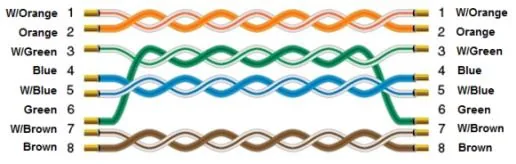
Wiring Diagram
The diagram below shows the Ethernet cable wiring.